UK
DCF
6
PLEASE READ CAREFULLY THIS MANUAL BEFORE PROCEEDING WITH
THE INSTALLATION.
Thank you for choosing GI.BI.DI.
• Before proceeding with installation, fit a magnetothermal or differential switch with a maximum
• Make the connections referring to the following tables and to the attached screen-print. Be extremely
careful to connect in series all the devices that are connected to the same N.C. (normally closed) input,
and in parallel all the devices that share the same N.O. (normally open) input. Incorrect installation or
improper use of the product may compromise system safety.
• Keep all the materials contained in the packaging away from children, since they pose a potential risk.
• The manufacturer declines all responsibility for improper functioning of the automated device if the
original components and accessories suitable for the specific application are not used.
• After installation, always carefully check proper functioning of the system and the devices used.
• This instruction manual addresses persons qualified for installation of “live equipment”. Therefore, good
technical knowledge and professional practice in compliance with the regulations in force are required.
• Maintenance must be carried out by qualified personnel.
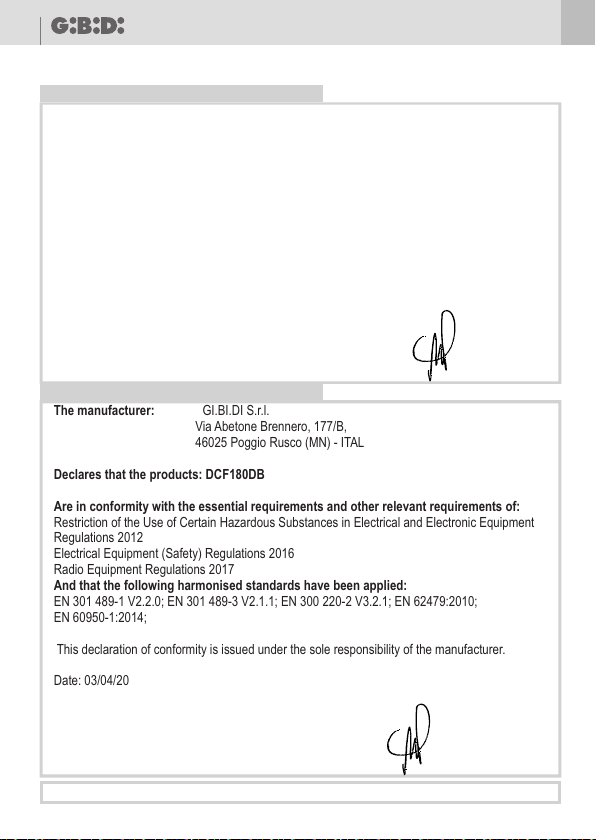
WARNINGS: This product has been tested in GI.BI.DI. verifying the perfect correspondence of the
characteristics to the current directive.
Gi.Bi.Di. S.r.l. reserves the right to modify the technical data without prior notice depending on the product
development.
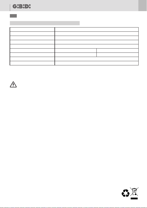
TECHNICAL SPECIFICATIONS
DISPOSAL: GI.BI.DI. advises recycling the plastic components and to dispose of them at
special authorised centres for electronic components thus protecting the environment
from polluting substances.
FUNCTIONING
DCF 7
UK
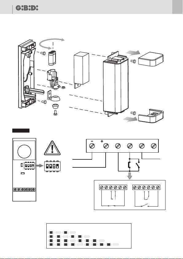
INSTALLATION
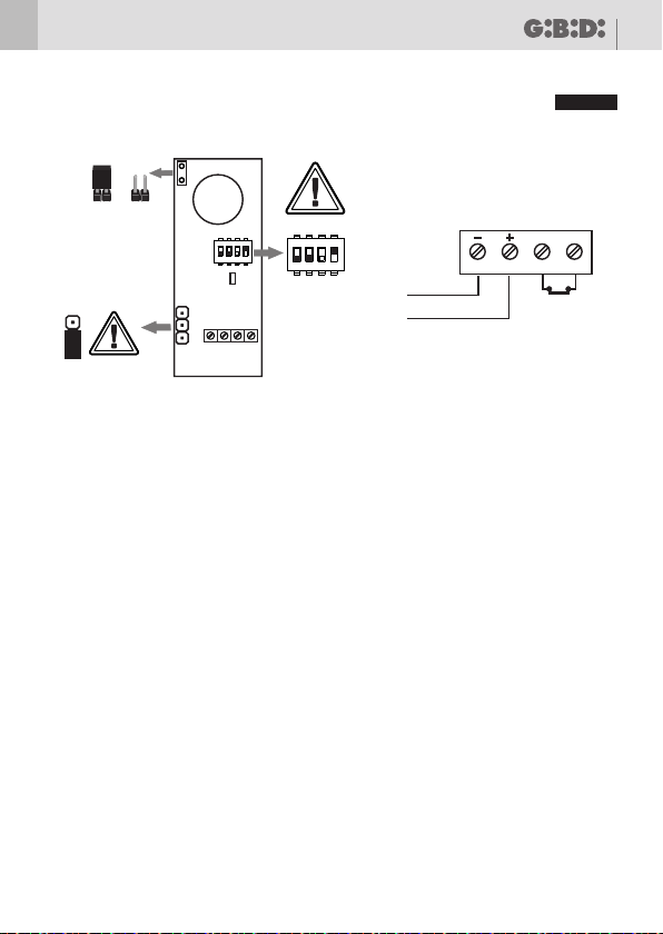
Fix the photocells and make connections as shown in Fig. 1 (RX) Fig. 2 (TX). Cover the photocell with the
front part and secure with the screws provided. Pass across the photocell range several times, to check
relay response.
The DCF180DB photocell has been designed mainly for use with sliding gates, which eliminates the need
for a mobile frame. The device can also be used as a normal photocell in all cases where the transmitter
cannot be wired. The receiver must be positioned so that it is not disturbed by other photocells.
Transmitter operation
The transmitter has a jumper (J1) for power selection. To decrease the photocell range (down to 10 m)
open the jumper(J1). The flashing red LED L1 indicates proper transmitter operation.
The transmitter must be powered with 3V alkaline batteries. Each battery lasts on average 24 months in
normal power conditions (jumper (J1) disabled) or approximately 12 months in high power conditions
(jumper enabled). This duration is valid for optimal climatic conditions and optimal conditions of
use; variations in climatic conditions and improper use will reduce battery life.
Receiver operation
The receiver has 2 LEDs. The first LED (L1), indicates proper signal reception (the signal is being received
if the LED is on ), while the second LED (L2) only flashes when the signal is present (otherwise it is off). The
time the LED is on indicates signal quality. So the longer the LED is on, the better quality signal.
The receiver must be powered with a 12 or 24 V DC (check polarities are correct), or AC power supply.
If this photocell is used for a range of less than 2 m, the lens should be removed and the J1 power jumper
on the transmitter opened.
IMPORTANT: transmitters of other photocells must be positioned so that their band does not
directly face the receiver of the battery-operated photocell. If the above is not observed, normal
operation is not guaranteed.
The power supply of the transmitter with a battery can reduce the transmission, in such cases the receiver
can be interferated from infrared rays. To avoid this inconvenience, put the DIP 3 in OFF (RX).
IP
Model/Item
Range
Signal
Infrared frequency
Relay power
Power supply
Absorption
Operating temperature
30 m (12 m, external)
Impulse signal, unmodulated
100 Hz ÷ 1 Khz
RX:12/24 V dc/ac
TX: 0,04mA÷ 0,12mA
-20 ÷ +60 °C
DCF180DB / AU02020
54
TX: 2 x AAA 1,5V
RX: 35mA
0,5A 48Vac/dc