Projecta HDBM35 User manual

INTELLI-CHARGE WORKSHOP
35A 12/24V & 150A 12V
BATTERY MANAGER
P/No.s HDBM35, HDBM150

GENERAL INFORMATION
OVERVIEW
This series of workshop chargers are designed for industrial usage in the modern workshop
environment. They can be used for a range of applications from Battery Charging &
Maintenance, Diagnostics & Power Supply, Showroom Battery Support and Battery Testing.
They are compatible with different Lead-Acid chemistries as well as new LiFePo4lithium
batteries. In Diagnostic mode they can output constant voltage for various vehicle service
operations such as fault finding, module re-programming and battery support during
other operations. In the Showroom mode they can supply the current needed by a vehicle
in Demonstration mode allowing all of the features of the vehicle to be shown without
draining the battery. The Test function can be used to check the condition of the vehicle’s
starting battery as well as the starter motor. The workshop chargers also feature a self-
calibration mode in the event of any component changes.
MAIN FEATURES
• Advanced SMPS technology and patented battery charging and reconditioning
technology.
• Power factor correction (PFC).
• Automatic multi step charging mode.
• Ability to properly charge multiple battery types: Flooded, AGM, EFB, GEL and Lithium
(LiFePo4) batteries.
• Multiple rates of charge and charging parameters to suit various battery capacities.
• Automatic detection of: short-circuited battery cells and sulphated batteries.
• Automatic reconditioning and cell balancing.
• Diagnostic mode featuring constant voltage output.
• Showroom mode ensures power compensation for a vehicle in Demonstration mode.
• Modern Color TFT display and intuitive user interface.
• Auto-detect – automatic restart function in both Charge and Showroom mode following
a cut in AC power.
• Charge and Showroom mode settings automatically memorised by Auto-detect system.
• DC Output charging cable integrity check function.
• Firmware update compatible through USB port.
22

IMPORTANT SAFETY INFORMATION
SAVE THESE INSTRUCTIONS, THIS MANUAL CONTAINS IMPORTANT SAFETY AND
OPERATING INSTRUCTIONS KEEP IT WITH OR NEAR THE CHARGER AT ALL TIMES.
WARNING
• RISK OF EXPLOSIVE GASES WORKING IN VICINITY OF A LEAD-ACID BATTERY IS
DANGEROUS. EXPLOSIVE GASES DEVELOP DURING NORMAL BATTERY OPERATION.
IT IS IMPORTANT THAT EACH TIME BEFORE USING YOUR CHARGER, YOU READ THIS
MANUAL AND FOLLOW THE INSTRUCTIONS EXACTLY.
This device has been designed for trained professionals and according to the codes of
practice valid at that time. It is safe to operate, but please make sure to read and understand
this user manual beforehand. It can be dangerous if it is used by non-professionally trained
personnel or in an incorrect way.The manufacturer cannot be held responsible for the
incorrect use of this device. Please follow these steps for maximum safety.
• For indoor use. Do not expose to rain.
• Always wear safety equipment: goggles, gloves, ear protection and appropriate attire.
• Only use accessories or attachments approved by the manufacturer.
• Modifications or alterations to this device are forbidden. Repairs and service can only be
performed by an official authorized center. Damaged cords, cables, chargers or devices
must be immediately fixed or replaced.
• Explosive gases may be released by a battery when charging - it must be placed in a
well-ventilated area, away from flames and sparks.
• Avoid short circuits and never have the clamps touch each other, or any metal part at
the same time.
• This appliance can be used by children from 8 years and above and persons with
reduced physical, sensory or mental capabilities, or lack of experience and knowledge,
only if they have been given supervision or instruction concerning use of the appliance
in a safe way and understand the hazards involved.
• Children shall not play with the appliance and should be supervised to ensure this.
PRODUCT OVERVIEW
1. AC Input Socket
2. Main On/Off Switch
3. USB Firmware Update Port
4. DC Output Sockets (+/-)
5. Menu Navigation Keys
6. TFT Display
3

• Cleaning and user maintenance shall not be made by children without supervision.
• To reduce risk of a battery explosion, follow these instructions and those published by
the battery manufacturer and/or the manufacturer of any equipment you intend to use
or have nearby. Review all the cautionary markings.
• Do not expose charger to rain, snow, or liquids. Never submerge in water, burn or throw
away in domestic waste.
• Safety equipment, such as fire extinguisher or water to rinse eyes, should always be
nearby. Also make sure someone else is nearby in case of emergency.
• If battery acid enters in contact with your eyes, skin or clothing, wash immediately with
soap and water. If acid enters in contact with your eyes, immediately flush them with
running cold water for at least 10 minutes and get medical attention immediately.
• Remove personal metal items when working near engines/motors and batteries.
• Always read the vehicle’s user manual before connecting any charger to the vehicle or
its battery.
• Do not attempt to charge a marine (boat) battery while the boat is on or near the
water. A boat must be on a trailer and located indoors before attempting to charge its
battery(s). The boat manufacturer’s instructions must be followed exactly.
• To reduce risk of damage to the electric plug and cord, pull the plug rather than the cord
when disconnecting the charger.
• If the supply cord is damaged, it must be replaced by the manufacturer, its service agent,
or similarly qualified persons in order to avoid a hazard.
• An extension cord should not be used unless absolutely necessary. Use of improper
extension cord could result in a risk of fire and electric shock. If an extension cord must be
used, make sure that the pins on plug of the extension are the same as on the charger, and
that the extension cord is properly wired and in good electrical condition. The wire size
must be large enough and related to the AC amperage rating of the charger.
• If this device has been dropped, is damaged or is leaking, please have it controlled right
away by an authorized agent.
• Appliances containing batteries which contain hazardous materials for the environment:
a) Batteries contain lead and dilute sulfuric acid. Dispose of the battery in accordance
with federal, state and local regulations. Do not dispose of the battery in a landfill,
lake or natural environment. It must be recycled properly.
b) Scrap and replace the VRLA battery at or before the time indicated on the battery
or in the user’s manual. Usage beyond the required time of service can cause fluid
leakage due to damages to the container, or cause fire due to power leakage.
• Battery chargers for charging automobile batteries:
a) The battery terminal not connected to the chassis has to be connected first. The
other connection is to be made to the chassis, remote from the battery and fuel line.
The battery charger is then to be connected to the supply mains.
b) After charging, disconnect the battery charger from the supply mains. Then remove
the chassis connection and then the battery connection.
44

• NEVER smoke, allow a spark or flame in vicinity of battery or engine.
• Do not use the battery charger for recharging dry-cell or non-rechargeable batteries that
are commonly used with home appliances. These batteries may burst and cause personal
injuries and/or property damages.
• NEVER charge an inappropriate type of battery, or an inappropriate voltage.
• Always store the clamps correctly after each use.
• Battery acid and gases can be dangerous, never touch or inhale them. Be careful when
operating inside engine bays. Moving parts may cause injuries. Never use this device to
start or recharge a frozen (very cold) battery. It could be very dangerous.
• Always check the voltage of the vehicle’s battery before trying to recharge it.
• Please recycle this device, batteries and their packaging properly. Always keep the device
at room temperature.
PREPARING TO CHARGE
• If it is necessary to remove the battery from the vehicle before charging, ensure that the
vehicle is off before disconnecting the battery. When disconnecting, always remove the
negative battery connection first. Ensure that the environment around the battery and
charger is well ventilated.
• Clean the battery terminals (Be careful to keep any dislodged corrosion away from your
skin and eyes). If needed, add distilled water to each battery cell until the acid reaches
the level specified by the battery manufacturer. This helps purge excessive gas from the
cells. Do not overfill. Carefully read and follow the vehicle and battery manufacturer’s
recharging instructions. Specific precautions, such as removing or not removing the cell
caps while charging and recommended rates of charge should be followed.
• Determine the voltage of the battery, according to the vehicle’s or battery manufacturer
and ensure it matches the output characteristics of the battery charger.
CHARGER LOCATION AND CONNECTION PRECAUTIONS
• Place the charger as far away from battery as the cables permit. Never place the charger
directly above the battery being charged, or vice versa. Gases from the battery will
damage the charger, never allow battery acid to drip on the charger.
• Do not operate the charger in a closed area or without adequate ventilation.
• The charger must be disconnected from the AC supply before connecting or
disconnecting from a battery.
• Never allow the clamps or output terminals to touch each other creating a short circuit.
• If problems arise connecting the output leads, solicit the aid of your Dealer to find a
solution for your application. 5

66
STEPS WHEN A BATTERY IS INSTALLED INSIDE THE VEHICLE.
A SPARK NEAR A BATTERY MAY BE DANGEROUS. HOW TO REDUCE THIS RISK:
• Ensure that any cables are far from moving parts or pinch points when using the
charger.
• Stay clear of fan blades, belts, pulleys, and any other parts that could cause personal
injury.
• Ensure that the polarity of the connections is correct: the POSITIVE (Red, POS., P, +) post
usually has a larger diameter than the NEGATIVE (Black, NEG., N, -). If you are unsure,
use a voltmeter to check the terminal polarities.
• Determine which post of battery is grounded (connected) to chassis; For negative-
grounded vehicles, first connect the POSITIVE clamp to the POSITIVE (POS., P, +)
ungrounded terminal of battery. Then connect the NEGATIVE clamp to the vehicle’s
chassis or engine block away from the battery.
• Do not connect the charger to any part of the vehicle other than the battery terminals or
negative ground post.
• Connect charger AC supply cord to electrical outlet
• When disconnecting charger, turn the charger off, disconnect the charger from the AC
power, remove the clamp from the chassis, and then remove the clamp connected to the
battery terminal. See operating instructions for duration of charge information.
FOLLOW THESE STEPS WHEN THE BATTERY IS OUTSIDE THE VEHICLE.
WARNING: SPARKS NEAR A BATTERY MAY CAUSE EXPLOSIONS.
• Check the polarity of the battery terminals. (+ / -)
• Connect the Positive clamp to the Positive battery terminal.
• Position yourself as far away from battery as possible and connect the Negative clamp
to the Negative battery terminal.
• Do not face the battery when completing the connections.
• Connect the AC supply cable to the electric socket and turn the charger on.
• When disconnecting the charger, complete the steps in reverse.
7
OPERATING INSTRUCTIONS
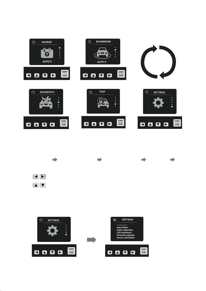
1.BROWSING THE MAIN INTERFACE
2.MAIN INTERFACE MODE
The device provides 5 Main Interface with the following modes:
CHARGE MODE SHOWROOM MODE DIAGNOSTIC MODE TEST MODE
SETTINGS MODE
Press to enter the Main menu or return to the previous menu.
Press to cycle between the various modes and settings
3.SETTINGS

Operation:
Step 1: Press to ENTER the SETTING submenu.
Step 2: Press to Select the desired setting.
Step 3: Press to CONFIRM and proceed into the desired settings menu.
Settings Displayed: LANGUAGE; AUTO-DETECT; CABLE CALIBRATION; LCD
BRIGHTNESS; FIRMWARE UPDATE; DEVICE INFO
LANGUAGE SETTINGS
Operation:
Step 1: Press to ENTER the LANGUAGE Submenu.
Step 2: Press to Select the desired language.
Step 3: Press to Confirm the selected language.
Languages Displayed: English; French, Germany, Spanish, Russian, Italian, Dutch
AUTO-DETECT SETTING
Operation:
Step 1: Press to ENTER the AUTO - DETECT Submenu.
Step 2: Press to Select the desired setting.
Step 3: Press to Confirm the AUTO - DETECT setting.
Settings Displayed: CHARGE ON / OFF; SHOWROOM ON / OFF
If the AUTO-DETECT is ON, the charger will automatically restart the CHARGE or
SHOWROOM modes following an AC power cut. Please see the CHARGE MODE or
SHOWROOM MODE introduce in the sections 4. and 6.
CABLE CALIBRATION SETTING
Operation:
Step 1: Press to ENTER the CABLE CALIBRATION Submenu.
Step 2: Connect the positive and negative clamps together ensuring a solid connection.
Step 3: Press the Start/Stop button. The charger will automatically test the output cables.
Settings Displayed:
88
Important: If the DC output cables need
to be replaced, consult your distributor to
order a replacement set. Only DC output
cables approved by the manufacturer
can be used with this device, once the
cables have been replaced, they must be
calibrated as shown above.

LCD BRIGHTNESS SETTING
Operation:
Step 1: Press to ENTER the LCD BRIGHTNESS Submenu
Step 2: Press to Set the desired brightness level.
The default setting is set at 50%.
FIRMWARE UPDATE SETTING
Operation:
Do not attempt to update the Firmware with any other updates than those
released by the manufacturer. Critical damage can occur if unapproved updates
are applied or updates are applied incorrectly.
Step 1: Download the firmware update onto an empty USB storage device. Connect the
storage device to the Charger through the USB port.
Step 2: Press to Enter the Firmware update submenu
Step 3: Press to set the four-digit code provided by the manufacturer to unlock
the update mode.
Step 4: Press the Start/Stop button. The device will automatically update the firmware
version.
Step 5: Once the firmware update is complete, press any key to restart the charger with
the updated software.
DEVICE INFORMATION
Operation:
Press to Enter the Device information display:
Display: Firmware version, the TFT firmware version, the Product rating, etc.
4.CHARGE MODE
The chargers advanced software is optimized to correctly and completely charge a wide
variety of battery types and chemistries; including Lead-Acid (WET/Flooded, AGM, EFB,
GEL) and Lithium (LiFePo4).
Once the CHARGE Mode is selected, the charging voltage, battery type and charging
voltage can be entered.
Ensure that the input parameters (nominal voltage, battery type, charging current)
are correct for the battery that you are attempting to charge, that they meet the
battery manufacturer’s specifications and that you have read the battery’s recharging
instructions. Failure to respect the battery specifications may result in damage to the
charger, the battery, the vehicle, property, or personal injury.
9

Charging Mode Operation:
Step 1: Press to ENTER or EXIT the charge mode
Step 2: Press to Select the desired parameter
Step 3: Press to Start or Stop the charging process.
Displayed Values During Charging:
Charging Percentage: indicates percentage of charge (%).
Current: displays the charging current (A)
Voltage: displays the charging voltage (V)
Ah: displays the Amp-hours recharged.
Time: displays the duration of charge
Smart Charging Process:
Important: Ensure the selected mode and parameters match the type of battery
you are attempting to charge
7-stage charging process for Lead-Acid Batteries:
De-Sulphation (if needed) Soft-Start Bulk Charge Absorption Analysis
Equalization Float Charge (21 Days reset period)
1010
5-stage charging process for LiFePO4 Lithium Batteries
Soft-Start Bulk Charge Absorption (CV1+CV2) Recharge 21 Days reset period

Charging Processes:
De-Sulphation:
In this stage rising voltage and high current pulses are applied to the battery to recover
sulphated batteries.
De-sulphation current control: 25% of Bulk current delivered.
Soft-Start:
In this stage rising voltage and a maximum of 50% of bulk stage current is applied to
the battery to begin the charging process.
Bulk Charge:
In this stage rising voltage and maximum user defined current is applied to the battery.
• 5~100Amp adjustable for the HDBM150
• 1~35Amp adjustable for the HDBM35
Absorption:
In this stage a constant voltage and tapering current is applied to the battery to ensure
it reaches 80% state of charge.
Absorption stage voltages for each battery chemistry:
GEL Battery 14.1V
AGM Battery 14.4V
EFB Battery 14.5V
WET/Flooded Battery 14.7V
LiFePO4Battery Absorption CV1 =14.0V
Absorption CV2 =14.2V
x2 for 24V mode (HDBM35 only)
Analysis:
In this stage the charger tests the battery again in order to detect bad cells and high
levels of sulphation (only for Lead-Acid batteries).
Equalization:
In this stage a higher voltage and low current is applied in order to balance the internal
cells of the battery (only for Lead-Acid batteries).
11
Maximum equalization stage voltages for each battery chemistry:
AGM BATT 14.5V
WET/Flooded Battery 14.6V
Flooded BATT 15.5V
Equalization current control 15% of Bulk Current
x2 for 24V mode (HDBM35 only)
Remarks: the interface will display 80~99% charged during the Absorption and
Equalization stage.
Float:
Compatible only with Lead-Acid batteries this stage is used for long term battery maintenance.
Float Voltage: 13.6V
Remarks: the interface will display 100% charged during the Float stage. If the voltage
falls below 12.5V, the charger will automatically return to the Bulk mode.
LiFePo4Recharge Stage:
If the battery voltage falls below 12.8V, the charger will automatically return to the Bulk mode.
If AUTO-DETECT is ON: the charger will automatically restart the charging process from
where it was interrupted in case of a cut in AC power.
5.DIAGNOSTIC MODE (POWER SUPPLY MODE)
The charger will act as a stable, configurable power supply during vehicle
diagnostics, repair and module programming.
Step 1: Press to Enter or Exit this Mode.
Step 2: Press to Select the desired parameters:
Battery Voltage; Output voltage, Maximum Output Current.
Step 3: Press to Start or Stop the mode.
Displayed Values During Diagnostics:
Load percentage: displays the load on the charger (%)
Current: displays the output current (A)
Voltage: displays the output voltage (V)
Watt: displays the output power (W)
Time: displays the duration
Output voltage control: 12~15v (x2 for 24V mode) adjustable
Output Current Control: 5~150Amp adjustable for the HDBM150 units /
1~35Amp adjustable for the HDBM35 units.
1212
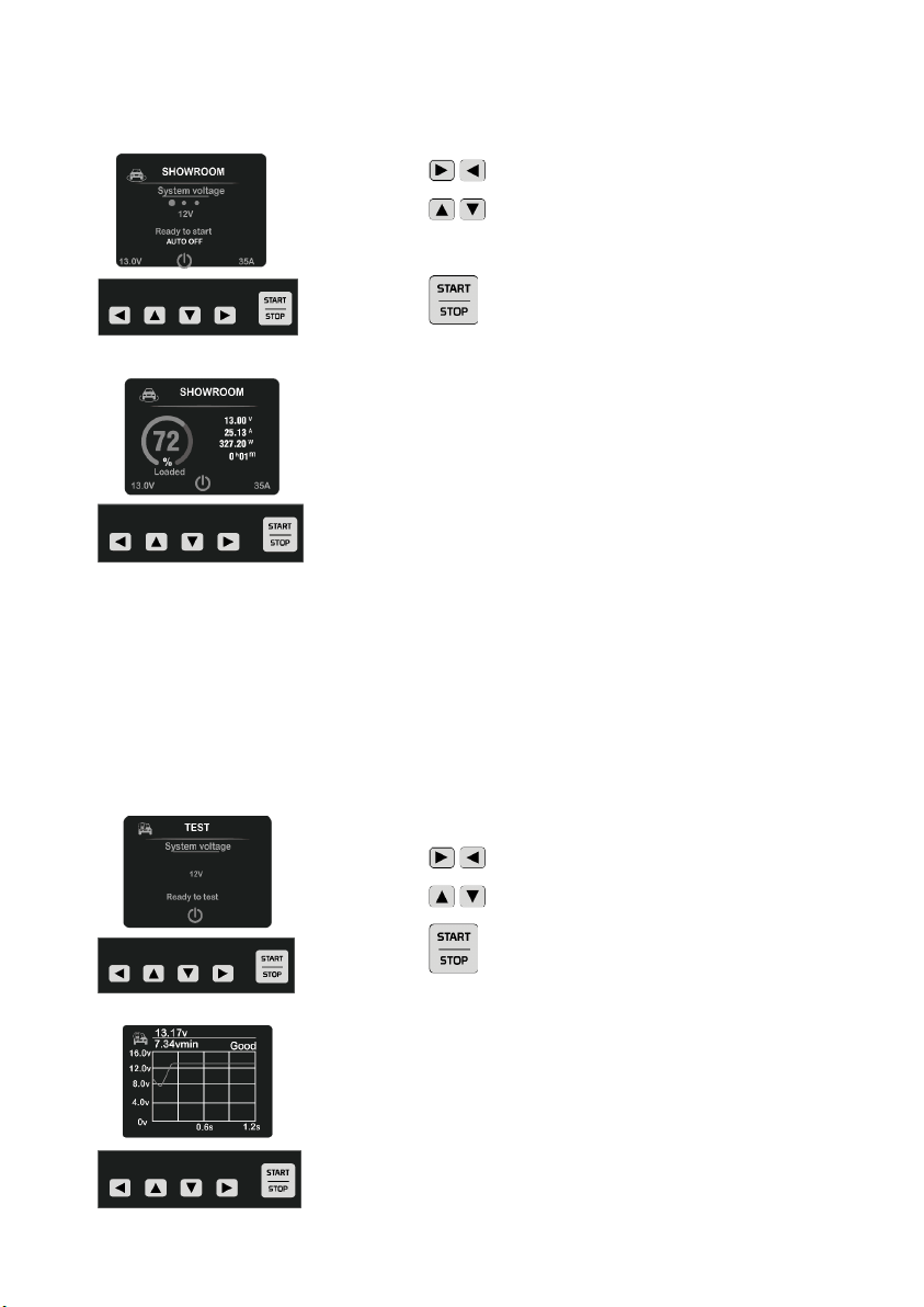
6.SHOWROOM MODE (POWER SUPPLY MODE)
Supply power to, and maintain the battery of vehicles in demonstration mode:
Step 1: Press to Enter or Exit the mode.
Step 2: Press to Select the desired parameter:
Battery Voltage; Output voltage, Output current.
Step 3: Press to Start or Stop Showroom mode.
Display in Showroom Mode:
Load percentage: displays the load on the charger (%)
Current: displays the output current (A)
Voltage: displays the output voltage (V)
Watt: displays the output power (W)
Time: displays the duration
Output Voltage: Adjustable between 12.6 - 14.5V (x2 for 24V mode HDBM35 only).
Output Current: Adjustable between 5 – 150Amp for the HDBM150 and 1 – 35Amp for
the HDBM35.
7.TEST MODE
Test both the vehicle’s battery and starting system performance. (Voltage and
waveform)
Step 1: Press to Enter or Exit this mode.
Step 2: Press Select the correct voltage:
Step 3: Press to Start or Stop the Testing process.
Display in Test Mode:
Battery Voltage: displays the vehicle’s battery voltage (V)
Starting System: displays the voltage waveform and
minimum voltage
Test Result: Excellent, Good, Needs to be recharged, Bad
13

8.ABNORMAL DISPLAY AND TROUBLE SHOOTING
Abnormal Condition Possible Cause Suggested Solution
No battery detected Loose connection Check the battery and terminal
connections
Battery short circuit Incorrect connection Check the battery and cables
connections
Inverse battery connections Incorrect connection Reverse the polarity of the
connection to the battery
Voltage is too low If the battery voltage is
less than 2-4V, the charger
will not start to recharge
the battery automatically
Press and hold for 3 seconds
to force the charging process to
start (Check the connections before
activating this function)
Voltage is too high 12V batt. set with the
24V mode Change to the correct 12/24V mode
Battery bad cell protection Battery has failed Replace the battery
Over-temperature
protection
The charger needs to
be checked Contact your distributor
Over voltage control
protection
The charger needs to
be checked Contact your distributor
Over current control
protection
The charger needs to
be checked Contact your distributor
Bad battery
(in Test mode)
Battery is short circuited
or has failed Replace the battery
Need to charge
(in Test mode)
Deeply discharged or
sulphated battery Use the Charge mode to
recharge the battery
1414
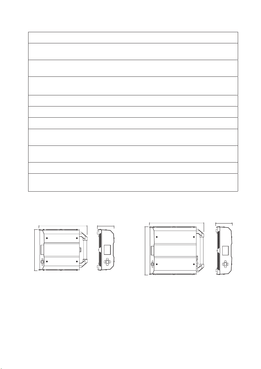
SPECIFICATIONS
Input voltage 220-240Vac 50/60Hz
Rated output 12/24Vdc 35A for HDBM35
12V Peak- 150A, Continuous 100A for HDBM150
Battery type Lead-Acid (WET/Flooded, AGM, EFB, GEL.)
or Lithium (LiFePO4) starter batteries.
Suitable for battery size 5-700Ah for HDBM35
20-2000Ah for HDBM150
Operating environmental -10~40°C, 0-90% RH.
Storage environmental -20~85°C, 0-90% RH.
Input cable size 1.0mm² 3C WITH 3Pin SAA Plug plus IEC-C14
Output cable size 3 metre 8mm2105°C with clamps for HDBM35
3 metre 25mm2105°C with clamps for HDBM150
Net weight Approx. 5.3 Kg for HDBM35
Approx. 9.2 Kg for HDBM150
Safety standards EN 60335-1, EN 60335-2-29, EMC Standards: EN55014
Dimensions HDBM35 (LxWxH: 311*253*105mm)
HDBM150 (LxWxH: 366*313*105mm)
15
253
311 105
313
366 105
HDBM35 HDBM150

WARRANTY STATEMENT
Applicable only to product sold in Australia.
Brown & Watson International Pty Ltd of 1500 Ferntree Gully Road, Knoxfield, Vic.,
telephone (03) 9730 6000, fax (03) 9730 6050, warrants that all products described in
its current catalogue (save and except for all bulbs and lenses whether made of glass or
some other substance) will under normal use and service be free of failures in material and
workmanship for a period of one (1) year (unless this period has been extended as indicated
elsewhere) from the date of the original purchase by the consumer as marked on the
invoice. This warranty does not cover ordinary wear and tear, abuse, alteration of products
or damage caused by the consumer.
To make a warranty claim the consumer must deliver the product at their cost to the
original place of purchase or to any other place which may be nominated by either BWI or
the retailer from where the product was bought in order that a warranty assessment may
be performed. The consumer must also deliver the original invoice evidencing the date and
place of purchase together with an explanation in writing as to the nature of the claim.
In the event that the claim is determined to be for a minor failure of the product then
BWI reserves the right to repair or replace it at its discretion. In the event that a major
failure is determined the consumer will be entitled to a replacement or a refund as well as
compensation for any other reasonably foreseeable loss or damage.
This warranty is in addition to any other rights or remedies that the consumer may have
under State or Federal legislation.
IMPORTANT NOTE
Our goods come with guarantees that cannot be excluded under the Australian Consumer
Law. You are entitled to a replacement or refund for a major failure and compensation for
any other reasonably foreseeable loss or damage. You are also entitled to have the goods
repaired or replaced if the goods fail to be of acceptable quality and the failure does not
amount to a major failure.
IS539
Issue 1 22.03.23
Distributed by
AUSTRALIA
Brown & Watson International Pty. Ltd.
Knoxfield Victoria 3180
Phone: (03) 9730 6000
Fax: (03) 9730 6050
National Toll Free: 1800 113 443
NEW ZEALAND OFFICE
Griffiths Equipment Ltd.
19 Bell Avenue,
Mount Wellington,
Auckland 1060, New Zealand
Phone: (09) 525 4575
This manual suits for next models
1
Table of contents
Popular Batteries Pack manuals by other brands

Promate
Promate Premium Sporty Back-up Battery Case for iPhone... user guide

LG Chem
LG Chem RESU10H StorEdge installation manual

Middle Atlantic Products
Middle Atlantic Products UPS-OLEBPR-1 user manual

Univercell
Univercell RLIF-MSI-1204 product manual

Growatt
Growatt APX 5.0P-B1 user manual

Panasonic
Panasonic CF-VZSU39U operating instructions


