Sime FORCED 200 User manual

FR
SIME FORCED 200 - 300
ENG
IT
ES

INDEX
Fonderie Sime SpA reserves the right to amend all of the product and relative accessories specications
without prior warning.

32


34
λ

7
0
10
110
815
915
925
4
0
13
148,5
188,5
338,5
1721,5
1871,5
1911,5
2047
2060
1
0
12
35
141
1299
2074
2105
2129
2
0
11,5
34
338
432
792
886
1190
1212,5
1224
3
0
15
55
490
925
965
980
6
5
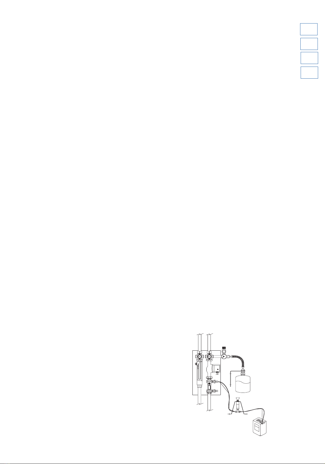
SUPPLY
Fig. 3

36
2
1
3
4
6
5
7
5a 5b
35°
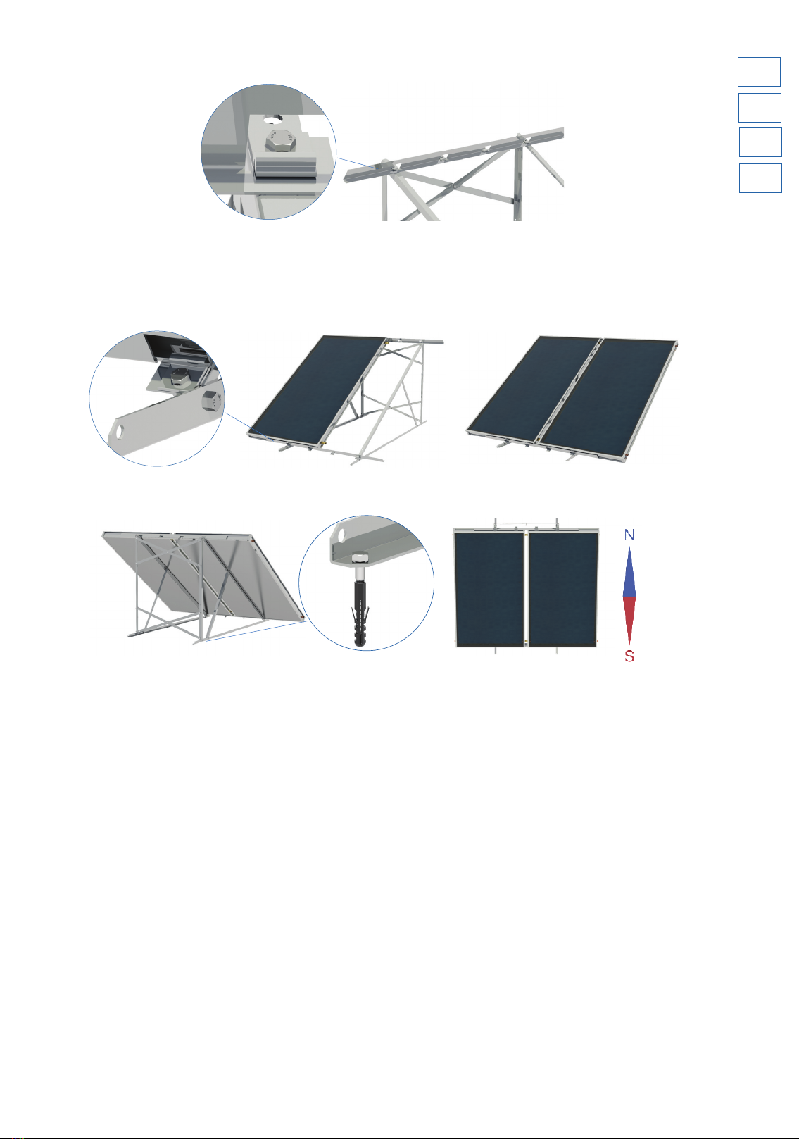
* Tighten the ttings ONLY. ANY BREAKAGE DUE TO THE TORSION OF THE PIPE BUNDLE IS NOT COVERED BY THE WARRANTY.
75

38
2
22
6
1
11
4
5
3a
5
7
7
35°
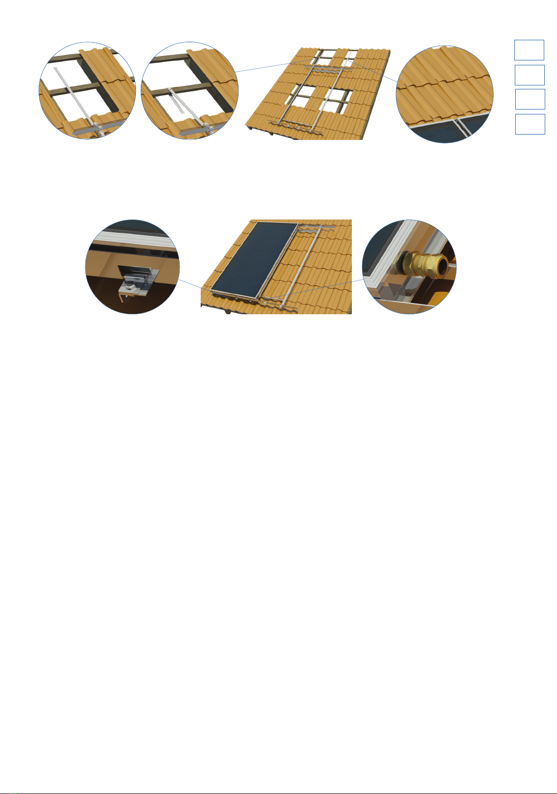
* Tighten the ttings ONLY. BREAKAGE DUE TO THE TORSION OF THE PIPE BUNDLE IS NOT COVERED BY THE WARRANTY.
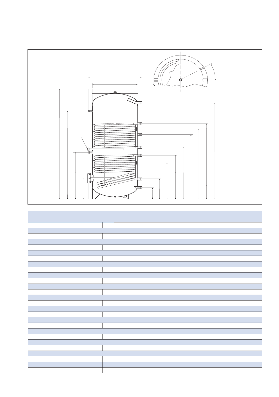
40
ø int.
C
ø est.
H
B
A
30ϒ
F
G
M
L
N
Q
R
P
S
BS 2S
3000 lt
Fig. 4
Dimensional values and hydraulic connections BS 2S
200
BS 2S
300
BS 2S
400
ΦΦ

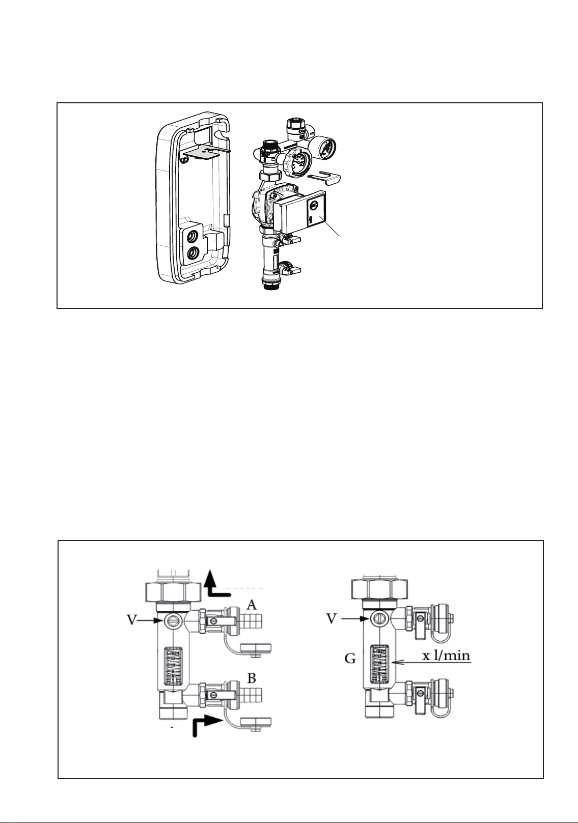
42
(Fig. 1)
(Fig. 2) (Fig. 3)
1- 2 3
9
87
6
5
4
3
1
2
10
LED indicator for
viewing the pump op-
erating status
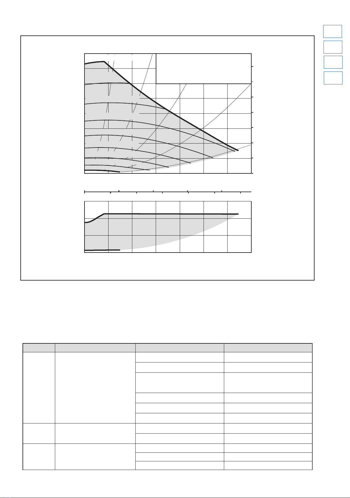
SOLAR UNIT HIGH EFFICIENCY PUMP
The solar unit circulator is the WILO type, model Yonos PARA ST 15/7 PWM (code 6272328). Find hereafter any
anomaly reported by the pump’s LED and the possible solutions:
HIGH EFFICIENCY PUMP CURVE (code 6272328)
0 0,5 1,0 1,5 2,0 2,5 3,0
0 0,2 0,4 0,6 0,8
02468 10
0
1
2
3
4
5
6
7
0
10
20
30
40
50
60
70
0 0,5 1,0 1,5 2,0 2,5 3,0
0
20
40
3695/ 25
PWM1
/75
PWM2
4178/ 15
PWM1
/85
PWM2
4660/ ≤5
PWM1
/≥95
PWM2
3213/ 35
PWM1
/65
PWM2
2730/ 45
PWM1
/55
PWM2
2248/ 55
PWM1
/45
PWM2
1765/ 65
PWM1
/35
PWM2
1283/ 75
PWM1
/25
PWM2
800/ 85
PWM1
/15
PWM2
Wilo-Yonos PARA ST 15/7.0
1~230 V - Rp½, Rp 1, Rp 1¼
n=1/min/ % PWM 1 / % PWM 2
p/kPa
H/m
P
1
/W
Q/m3/h
Q/l/s
Q/Igpm
Q/m3/h
max.
max.
External control via PWM
Pompa ad alta ecienza (cod. 6272328)
Eventuali anomalie della pompa e possibili rimedi
Colore LED Stato della pompaEventuale anomalia Possibile rimedio
Rosso-Verde
lampeggiante
Arresto di “blocco transitorio”;
Anomalia in corso
Dopo l’eliminazione dell’anomalia, la
pompa riparte automaticamente
Tensione di rete Troppo alta o troppo bassa;
(160V > Vn > 280V)- Veric are la tensione di rete
Sovra carico del motore; attrito o
bloccaggio della girante per presenza di
detriti
- Veric are le caratteristiche dell’acqua
dell’impianto; pulire l’impianto dai detriti
Velocità eccessiva; il rotore della pompa
è azionato, da un fattore esterno, oltre la
velocità massima consentita
- Veric are l’assenza di un usso esterno
(altra pompa in funzione) nell’impianto
Sovra corrente; l'avvolgimento di statore è
in corto circuito a causa dell'acqua
- Veric are l’assenza di perdite
nell’impianto
La temperatura all'interno del motore è
troppo alta
- Veric are il livello di temperatura
dell'acqua in rapporto con quello della
temperatura ambiente
La pompa è ostacolata da un usso esterno
(> 1200l/h) di direzione opposta
- Eliminare o ridurr e il usso esterno (<
1200l/h)
Rosso
lampeggianteArresto di “blocco permanente”
Pompa bloccata per detriti nell’impianto - Togliere e ridare l’alimentazione elettrica
(OFF – ON)
Guasto alla scheda elettronica e/o al
motore
- Se il “LED ros so” continua a lampeggiare:
- SOSTITUIRE LA POMPA
LED Spento Ferma
Mancanza di alimentazione elettrica - Veric are il collegamento
all’alimentazione elettrica
LED guasto- Vericare se la pompa può funzionare
Scheda elettronica guasta - SOSTITUIRE LA POMPA
Posibles fallos de la bomba y posibles soluciones
Color del LEDEstado de la bomba Posible falloPosible solución
Rojo-verde
parpadeando
Parada de “bloqueo temporal”; Fallo en
curso
Una vez corregido el fallo, la
bomba se vuelve a poner en marcha
automáticamente
Tensión de red demasiado alta o demasiado
baja;
(160V > Vn > 280V)
- Compruebe la tensión de r ed
Sobrecarga del motor; fricción o bloqueo del
rodete por presencia de detritos
- Compruebe las características del agua de
la instalación; elimine los detritos que haya
en la instalación
Velocidad excesiva; el rotor de la bomba
está accionado, por un factor externo, a una
velocidad que supera la máxima admitida
- Compruebe que no haya un ujo e xterno
(otra bomba en funcionamiento) en la
instalación
Sobrecorriente; el bobinado del estátor está
cortocircuitado a causa del agua
- Compruebe que no haya pérdidas en la
instalación
La temperatura interna del motor es
demasiado alta
- Compruebe el nivel de t emperatura del
agua en relación con el de la temperatura
ambiente
La bomba está obstaculizada por un ujo
externo (> 1200l/h) de dirección opuesta
- Elimine o reduzc a el ujo externo (<
1200l/h)
Rojo
parpadeandoParada de “bloqueo permanente”
Bomba bloqueada por detritos en la
instalación
- Desconecte y restablezca la alimentación
eléctrica (OFF – ON)
Avería en la tarjeta electrónica y/o en el
motor
- Si el “LED rojo” sigue parpadeando:
- SUSTITUYA LA BOMBA
LED apagadoParada
Interrupción de la alimentación eléctrica- Revise la c onexión a la alimentación
eléctrica
LED averiado - Compruebe si la bomba puede funcionar
Tarjet a electrónica averiada - SUSTITUYA LA BOMBA
Any pump faults and pos sible solutions
LED colour Pump status FaultPossible solution
Red-Green
ashing
"Transient safety shutdown"; Anomaly
in progress
After eliminating the anomaly, the pump
restarts automatically
Network voltage too high or too low;
(160V > Vn > 280V) - Check network v oltage
Motor overload; rotor friction or blockage
due to the presence of debris
- Check the charact eristics of the system
water; clean the system of any debris
Excessive speed; the pump rotor is
actuated by an external factor and is
rotating at a speed exceeding the maximum
permitted speed
- Check that there is no e xternal ow in the
system (no other pump in operation)
Overcurrent; stator winding is in short
circuit due to water- Check for l eaks in the system
The temperature inside the motor is too
high
- Check the water temperature in relation
to ambient temperature
The pump is obstructed by an external ow
(> 1200l/h) in the opposite direction
- Eliminate or r educe the external ow (<
1200l/h)
Flashing red "Permanent safety shutdown"
Pump blocked due to debris in the system- Remov e and reconnect the electrical
power supply (OFF - ON)
Fault in the electronic board and/or the
motor
- If the "red LED" continues to ash:
- REPLACE THE PUMP
LED o Stationary
No electrical power - Check the electric al power connection
LED faulty - Check if the pump can oper ate
Electronic board faulty- REPLACE THE PUMP
IT -
ENG -
ES -
44
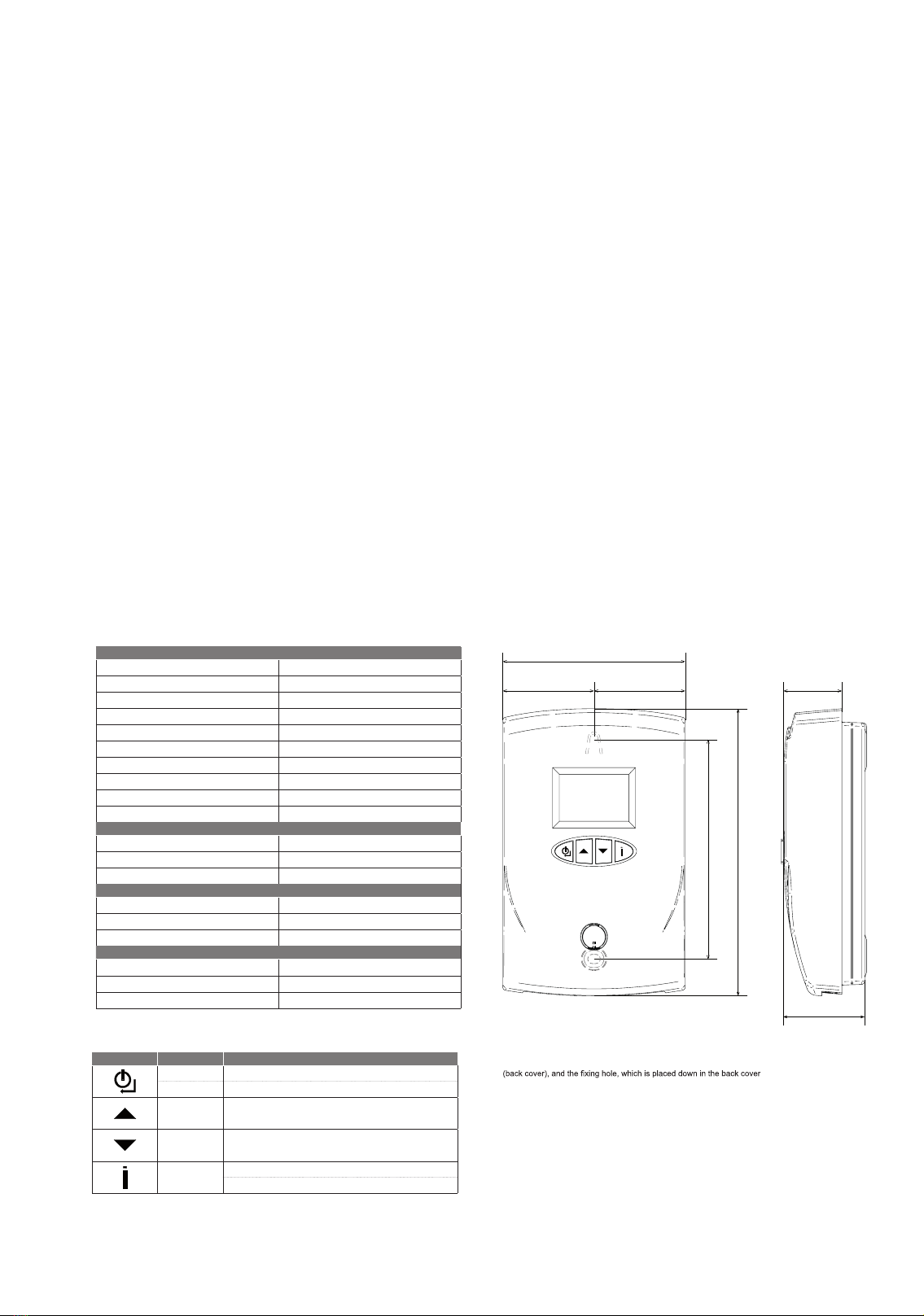
GI hydraulic unit.
Function of the buttons:
SERIGRAPHDESCRIPTION FUNCTION
ON/OFFTurn on or turn off the device
BACK Back to previous menu
INCREASE Go to next parameters or go to next value
DECREASEGo to previous parameter or go to previous value
INFO
Keep pressed for 1 sec.: Temperature information (S2, S3 - S1,S4)
Keep pressed for 10 sec.: Access to programming menu
GENERAL
Power supply 230 Vac +10% ÷ -15%
Frequency 50Hz +5% ÷ -5%
Range of working temperatures -20°C ÷ +60°C
Fuse 3,15AF (fast) 5x20
Varistor 300 Vac D7
SOLAR PUMP - P1 TRIAC (230 Vac) 0,5A – Cosφ 1
AUX 3 out - P1 PWM (230 Vac) 230Vac – 0,5A
AUX 2 out - P2 (230 Vac) 0,5A – Cosφ 1
AUX 1 out - Enabled thermostat /P20,5A – Cosφ 1
FREE CONTACT out - D1 (230 Vac) 230Vac – 0,5A
TEMPERATURE PROBE NTC
Range of correct work of the probes-40°C ÷ +105°C
Temperature in which the probe will indicate a fault -5°C>>T>>120°C
General tolerance on temperatures
(referred only to electronic board) ±1,5°C
TEMPERATURE PROBE PT1000
Range of correct work of the probes-40°C ÷ +250°C
Temperature in which the probe will indicate a fault -50°C>T>170°C
General tolerance on temperatures
(referred only to electronic board) ±1,5°C
ENVIRONMENTAL CONDITIONS OF USE
Ambient working temperature-20°C ÷ +60°C
Storage and transport temperature-30°C ÷ +60°C
Max. environment humidity (without any condensing) 95% a 40°C
TECHNICAL DATA
130 mm*
170 mm
108 mm
54 mm 54 mm 34 mm
48 mm
DIMENSIONS
The plastic box has protection rating IP20
*130 mm is the wheelbase between the holding hanger, which is set up in the front side of the device
.
S1
46

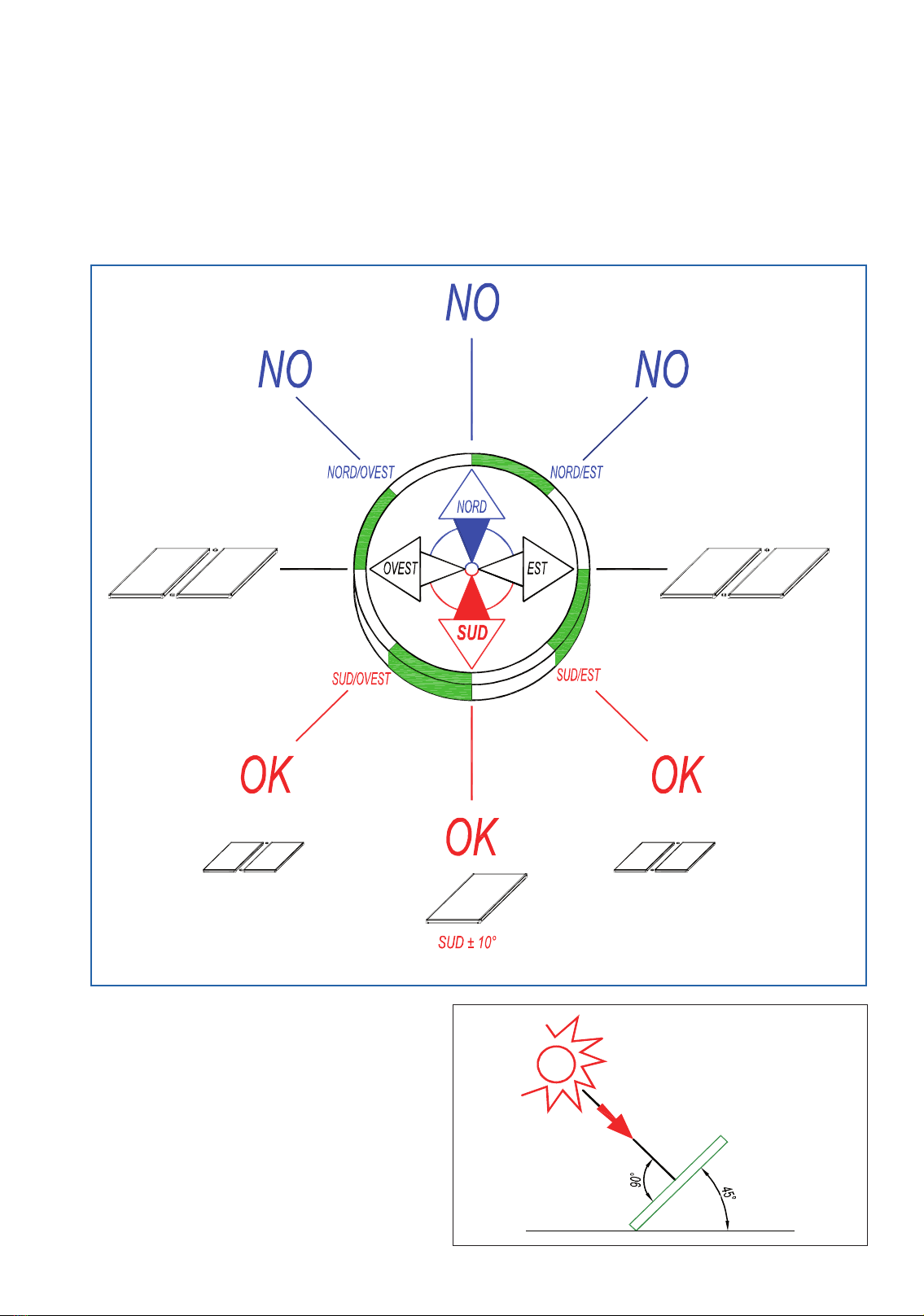
45° 45°
Pannello solare
220 220
540 162

48
TERMOSOLIS
“S1”
“S2”
DA RETE
ALL’UTILIZZO
DA RETE
S1
SB
S2

This manual suits for next models
1
Table of contents
Other Sime Inverter manuals


Popular Inverter manuals by other brands

Black & Decker
Black & Decker PI100BB instruction manual

Kraftixx
Kraftixx PPG 3500 Original operating instructions

Toshiba
Toshiba TOSVERT VF-AS1 Series instruction manual

Generac Power Systems
Generac Power Systems QT06030KVAN owner's manual

STORZ POWER
STORZ POWER SOL-ARK 12k installation manual

Selectronic
Selectronic LD700-24 operating manual


