Solaris PIX 72 User manual

USER MANUAL
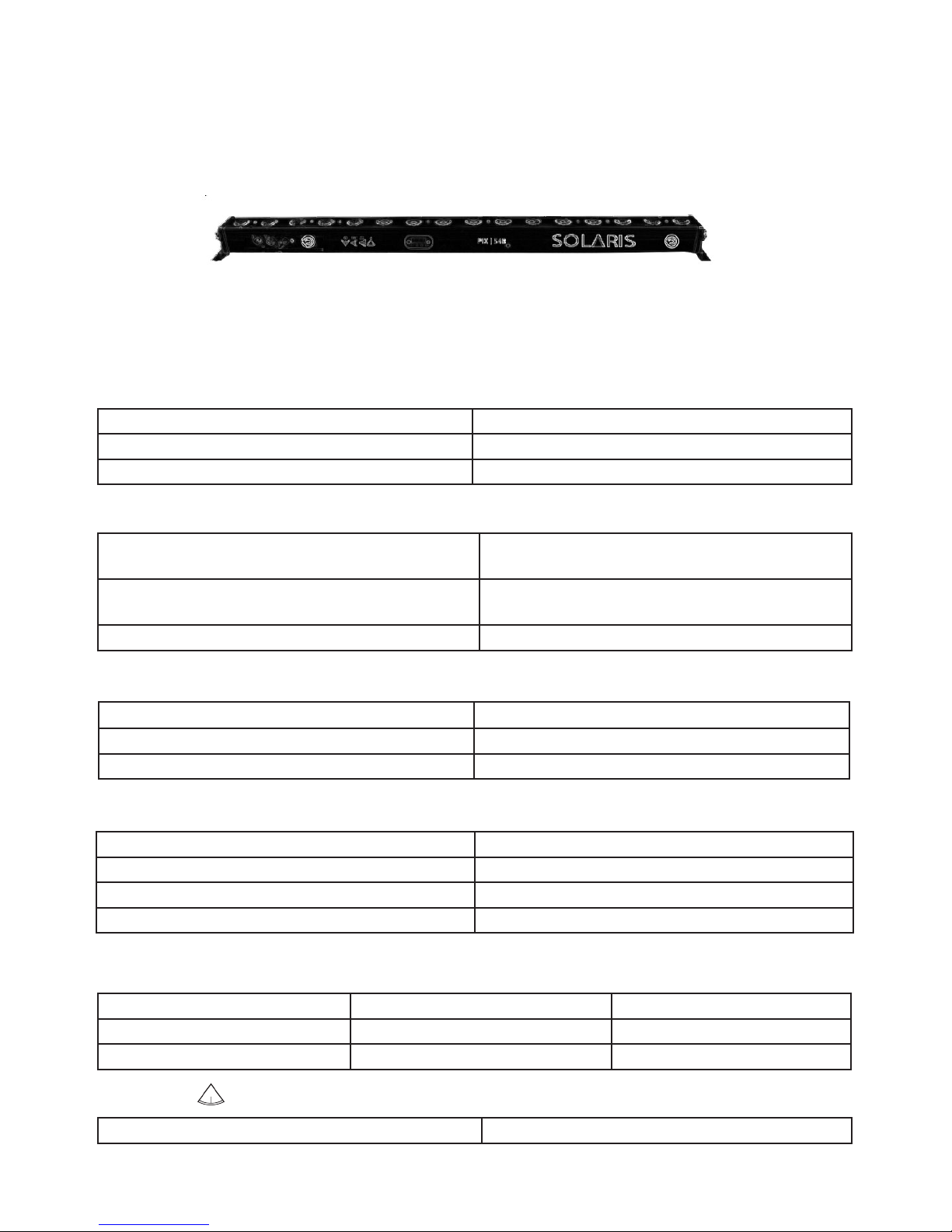
PIX |72
basic pixel bar 24x3w
SOLARIS® PIX 72™ 2
INDEX PAGE NO.
SAFETY INFORMATION 3-4
INTRODUCTION 5
INSTALLATION 6
AC POWER 7
FIXTURE OVERVIEW 8
DMX DATA LINK 9
CONNECTING AND USING DMX DATA LINK 9
FIXTURE OPERATION 10
TOKENS 11
FIXTURE MENU STRUCTURE CHART 12
DMX MODES CHARTS 13-14
MAINTENANCE 15
PIX 72 SPECIFICATIONS 16-17
INCLUDED ITEMS 17
TABLE OF CONTENTS
3SOLARIS® PIX 72™
WARNING!
READ THE SAFETY PRECAUTIONS IN THIS MANUAL
BEFORE INSTALLING
OPERATING OR SERVICING THIS PRODUCT.
SAFETY NOTES
Read all the following Safety Notes before working with this product.
These notes include important informaon about the installaon, us-
age, and maintenance of this product.
This product contains no user-serviceable parts. Any reference to ser-
vicing in this User Manual will only apply to properly trained GLOW®
Professional cered technicians. Do not open the housing or aempt
any repairs.
All applicable local codes and regulaons apply to proper installaon of
this product.
PERSONAL SAFETY
· Avoid direct eye exposure to the light source while the product is on.
· Always disconnect this product from its power source before servicing.
· Always connect this product to a grounded circuit to avoid the risk of
electrocuon.
· Do not touch this product’s housing during operaon because it may
be very hot.
MOUNTING & RIG-
GING
· This product is for indoor use only! To prevent risk of re or shock, do
not expose this product to rain or moisture. (IP20)
· Mount this product in a locaon with adequate venlaon, at least 20
in (50 cm) from adjacent surfaces.
· Make sure there are no ammable materials close to this product while
it is operang.
· Always carry this product by the handles. Do not carry from the head.
· When hanging this product, always secure to a fastening device using
a safety cable.
SAFETY INFORMATION

SOLARIS® PIX 72™ 4
POWER & WIRING
· Always make sure you are connecng this product to the proper volt-
age in accordance with the specicaons in this manual or on the prod-
uct’s specicaon label.
· Never connect this product to a dimmer pack or any rheostat.
· Never disconnect this product
OPERATION
· Do not operate this product if you see damage to the housing, lenses,
LED lights or cables. Have the damaged parts replaced by an authorized
technician at once.
· Do not cover the venlaon slots when operang to avoid internal
overheang.
· Do not aim this product toward the Sun. The lenses could concentrate
the solar energy and cause internal overheang.
· The maximum ambient temperature is 120 °F (49 °C). Do not operate
this product at a higher temperature.
· In case of a serious operang problem, stop using this product imme-
diately
In the unlikely event that your GLOW® product may require service, contact GLOW®
Technical Support.

5SOLARIS® PIX 72™
The SOLARIS® PIX 72™ is a high-performance 24 X 15W RGB 3 in 1 Pixel Led Bar lighng
xture featuring a Linear Dimmer & a light weighted body enclosure made of a sturdy alumi-
num casng, designed for xed indoor installaons.
The xture can be controlled using any DMX-compliant controller (2 Ch. | 3 Ch. | 4 Ch. |
6 Ch. | 7Ch. | 12 Ch. | 24 Ch. Modes) as well as automac operaon mode, sound to light
mode and manual mode.
BEFORE USING THE PRODUCT FOR THE FIRST TIME
1. Read ’Safety informaon’ on page 4 before installing, operang or servicing the xture.
2. Unpack and ensure that there is no transportaon damage before using the xture. Never
aempt to operate a damaged xture.
3. If the xture is not going to be hard-wired to a mains supply, aach a local power plug to
the end of the supplied power cable.
4. Before operang, ensure that the voltage and frequency of the power supply match the
power requirements of the xture.
5. Refer to the GLOW® website for the most recent user documentaon and technical infor-
maon about this xture.
INTRODUCTION
SOLARIS® PIX 72™ 6
INSTALLATION
The xture is designed for indoor use only and must be used in a dry locaon with adequate
venlaon. Ensure that none of the xture’s venlaon slots are blocked and ensure that the
xture is fastened to a secure structure or surface. Do not use the xture to illuminate sur-
faces less than 8 m (approx 26.) from the xture.
FASTENING THE FIXTURE TO A FLAT SURFACE
The xture can be fastened to a hard, xed, at surface that is oriented at any angle. Ensure
that the surface and all fasteners used can support at least 10 mes the weight of all xtures
and equipment they will support. Fasten the xture Securely. Do not place it on a surface or
leave it where it can be moved or fall over. If you install the xture in a locaon where it may
cause injury or damage if it falls, secure it as directed below with a securely anchored safety
cable that will hold the xture if the primary fastening method fails.
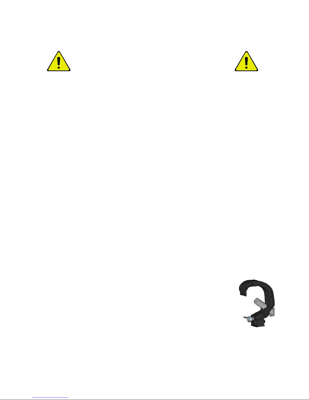
MOUNTING THE FIXTURE ON A TRUSS
The xture can be clamped to a truss or similar rigging structure in any orientaon. When
installing the xture hanging vercally down, you can use an open-type clamp such as a
G-clamp. When installing in any other orientaon, you must use a half-coupler clamp
that completely encircles the truss or pipe circumference. To clamp the xture to a truss:
1. Check that the rigging structure can support at least 10 mes the weight of all xtures and
equipment to be installed on it.
2. Block access under the work area.
3. Working from a stable plaorm, hang the xture on the
truss and fasten the rigging clamps onto the truss.
4. Secure the xture with a safety cable as directed below.
5. Check that the head will not collide with other xtures or objects.
SECURING WITH A SAFETY CABLE
Secure the xture with a safety cable (or other secondary aachment) that is approved for
the weight of the xture so that the safety cable will hold the xture if a primary aachment
fails. Loop the safety cable through and around a secure metal anchoring point.
WARNING! READ SAFETY INFORMATION ON
PAGE 3 BEFORE INSTALLING THE FIXTURE.

7SOLARIS® PIX 72™
Socket outlets or external power switches used to supply the xture with power must be
located near the xture and easily accessible so that the xtures can easily be disconnect-
ed from power.
Do not insert or remove power cable to apply or cut power, as this may cause arcing at the
terminals that will damage the connectors.
Do not use an external dimming system to supply power to the xture, as this may cause
damage to the xture that is not covered by the product warranty.
The xture can be hard-wired to a building electrical installaon if you want to install it
permanently, or a power plug (not supplied) that is suitable for the local power out-lets
can be installed on the power cable.
If you replace power plug on the power cable, install a grounding type (earthed) plug with
integral cable grip that is rated minimum 250 V, 5 A.
The xture has an auto-ranging power supply that accepts AC mains power at 100-240 V
at 50/60 Hz. Do not apply AC mains power at any other voltage or frequency to the xture.
For protecon from electric shock, the xture must be grounded (earthed). The
power distribuon circuit must be equipped with a fuse or circuit breaker and
ground-fault (earth-fault) protecon.
AC POWER
WARNING! READ SAFETY INFORMATION ON
PAGE 3 BEFORE INSTALLING THE FIXTURE.
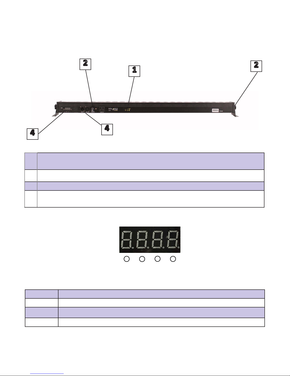
SOLARIS® PIX 72™ 8
1Tokens® – symbol indicang the xture DMX personality, Beam Angle, Weight and
Power Supply
2Power Connector Input (Built In)
3DMX data Link Input and Output XLR Connectors
4Digital Screen for accessing menu with 4 buons for navigaon: Up, Down Inc (In-
crement) and Dec (Decrement) Enter
UP Press UP to toggle between menu opons
DOWN Press DOWN to toggle between menu opons
INC Press INC to change current value by Incremenng the value displayed by 1
DEC Press DEC to change current value by decremenng the value displayed by 1
1
44
2
FIXTURE OVERVIEW
2
up down enter esc

9SOLARIS® PIX 72™
DMX DATA LINK
A DMX 512 data link is required in order to control the xture via DMX. The xture
has 3-pin XLR connectors for DMX data input and output. The number of daisy-chained
xtures is limited by the number of DMX channels required by the xtures in relaon to
the maximum 512 channels available in one DMX universe. Note that if independent con-
trol of a xture is required, it must have its own DMX channels.
Fixtures that are required to behave idencally can share the same DMX address and
channels. To add more xtures or groups of xtures when the above limit is reached, add
a DMX universe and another daisy-chained link.
CONNECTING AND USING DMX DATA LINK
To connect the xture to data:
1. Connect the DMX data output from the controller to the rst xture’s male XLR
DMX input connector.
2. Connect the rst xture’s DMX output to the DMX input of the next xture and conn-
ue connecng xtures output to input.

SOLARIS® PIX 72™ 10
FIXTURE OPERATION
This secon explains the xture sengs and ulies that the user has access to when us-
ing the control panel. Sengs are retained when the xture is powered o.
The SOLARIS® PIX 72™ can funcon in dierent modes:
CHANGING DMX CHANNEL MODE Scroll down using the up and down buons below
the digital screen and you will noce that the leer in the beginning changes but the
number 001 persist. (for example “A001” or “E001”) this display changes according to the
mode in which you are operang at that moment. Once you have selected the desired
dmx personality (also known as DMX footprint) Press the enter buon once to access edit
mode and then change the DMX values according to your setup. Oponal values are A001
(2CH mode), C001 (3CH mode), d001 (4CH mode), E001 (6CH mode), H001 (7CH mode),
L001 (12CH mode), P001 (24CH mode),
STANDALONE MODE which allows you to manually change the parameters of the xture
without using DMX data link. When operated in Standalone mode the xture back screen
will show R000 (Led Intensity) when rst accessed. By seng a value between 000-255,
using the up & down buons below the screen, you can control the desired dimmer level.
You can also manually control strobe ashing by changing the values when the back
screen shows FF00 (strobe ash) By seng a value between 01-20, using the up & down
buons below the screen, you can control the desired intensity of strobing.
It is also possible to use 16 predened factory eects, when rst accessing predened
eects back screen will show a value between 1 to 9 followed by the leer “J” for (Jump
eects) or “d” (for gradual eects) and another number between 00-20 (example: “1J09”
or 2d17) when accessed. The number between 1-9 is showing which of the 10 built-in
eects is selected while the number between 01 to 20 following the leer “J” is displaying
the speed of the built in eect. By seng a value from 1 to 9 you can change the pre-
dened built in eect you wish to apply. By seng a value from 01 to 20 you can change
the speed of the predened built in eect you wish to apply.
SOUND TO LIGHT MODE When operated in Sound to Light mode the xture back screen
will show Su00 when rst accessed. By seng a value between 00-20, using the up &
down buons below the screen, you can control The sound eect applied from slow to
fast according to the sound perceived by the unit’s built-in microphone.

11 SOLARIS® PIX 72™
TOKENS®
The TOKENS® are symbols we use to mark the features of our xtures. Every xture has
its own unique set of TOKENS® according to the xture’s qualies. Those marks can be
especially useful and informave for the technicians using Solaris xtures.
The TOKENS® are located above the digital screen on the back panel of the xture.
This token indicates the maximum amount of power consumpon
(Displays in Was)
This token indicates the angle of the xture’s beam (Displayed in degrees)
This token indicates the possible DMX footprint (DMX Personality) of the xture
(according to the dierent dmx modes of operaon)
This token indicates the weight of the xture (Displayed in Kilograms)

SOLARIS® PIX 72™ 12
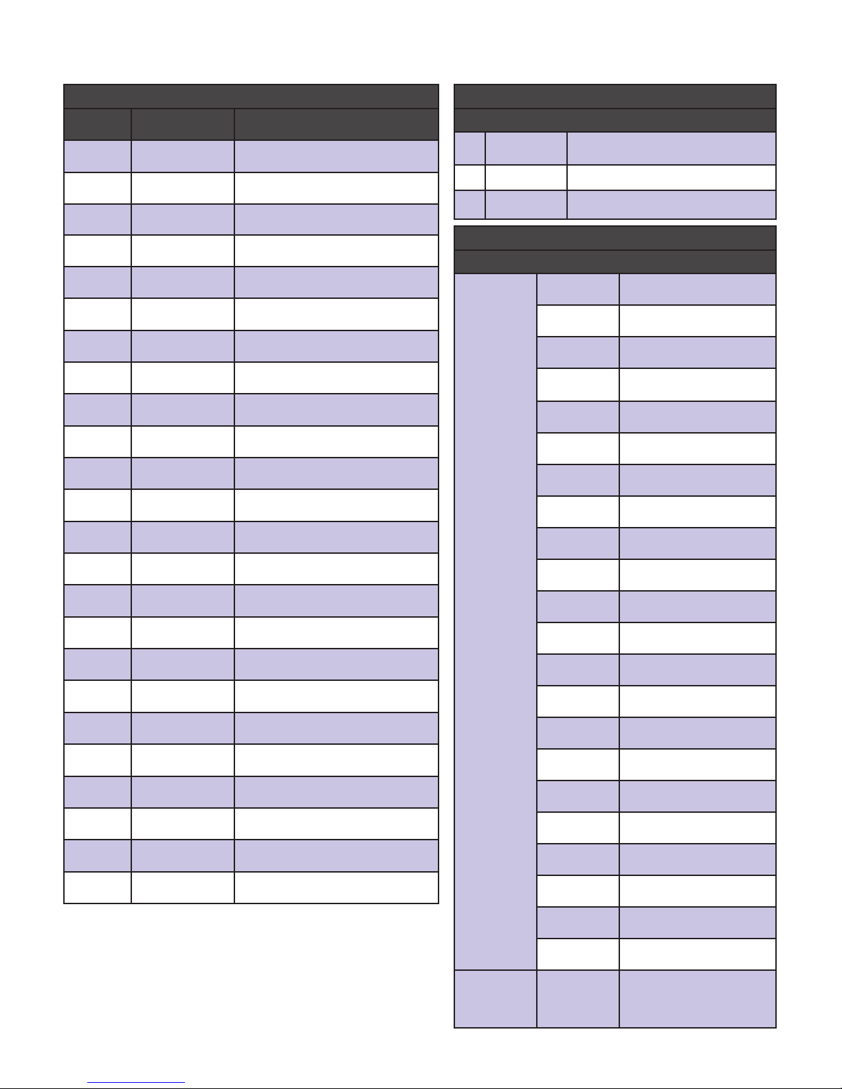
DISPLAY FUNCTION INSTRUCTIONS
1 A001 001- 512 DMX512 address setup - 2CH Mode
2 C001 001- 512 DMX512 address setup - 3CH Mode
3 d001 001- 512 DMX512 address setup - 4CH Mode
4 E001 001- 512 DMX512 address setup - 6CH Mode
5 H001 001- 512 DMX512 address setup - 7CH Mode
6 L001 001- 512 DMX512 address setup - 12CH Mode
7 P001 001- 512 DMX512 address setup- 24CH Mode
8 r255 000- 255 Red Dimmer, from dark to bright
9 G255 000- 255 Green Dimmer, from dark to bright
10 b255 000- 255 Blue Dimmer, from dark to bright
11 FF00 00- 20 RGB Strobe, speed from slow to fast
12 1J00 00- 20 Program Eect1, speed slow to fast
13 2J00 00- 20 Program Eect2, speed slow to fast
14 3J00 00- 20 Program Eect3, speed slow to fast
15 4J00 00- 20 Program Eect4, speed slow to fast
16 5J00 00- 20 Program Eect5, speed slow to fast
17 6J00 00- 20 Program Eect6, speed slow to fast
18 7J00 00- 20 Program Eect7, speed slow to fast
19 8J00 00- 20 Program Eect8, speed slow to fast
20 9J00 00- 20 Eect 1-8circulate run, speed slow to fast
21 1d00 00- 20 Red Gradual change, speed slow to fast
22 2d00 00- 20 Green Gradual change, speed slow to fast
23 3d00 00- 20 Blue Gradual change, speed slow to fast
24 4d00 00- 20 Purple Gradual change, speed slow to fast
25 5d00 00- 20 Orange Gradual change, speed slow to fast
26 6d00 00- 20 Red,Green,Blue,Purple,Orange Color Circulate
Gradual change, speed from slow to fast
27 SU00 00- 20 Sound Program Eect, speed from slow to fast
FIXTURE MENU STRUCTURE CHART

13 SOLARIS® PIX 72™
7 CHANNELS MODE
NO. DMX VALUE FUNCTION
1 000-255 Master LED Dimmer 1-100%
2 000-255 RED LED Dimmer 1-100%
3 000-255 GREEN LED Dimmer 1-100%
4 000-255 BLUE LED Dimmer 1-100%
5 000-255 9-10# LED Dimmer 1-100%
6
000-011 No eect
012-023 LED Color Red
024-035 LED Color Green
036-047 LED Color Blue
048-059 LED Color Yellow
060-071 LED Colo Purple
072-083 LED Color Cyan
084-095 LED Color White
096-107 Program Eect -1
108-119 Program Eect -2
120-132 Program Eect -3
133-143 Program Eect -4
144-155 Program Eect -5
156-167 Program Eect -6
168-179 Program Eect -7
180-191 Program Eect -8
192-203 Program Eect -9
204-217 Program Eect -10
218-227 Program Eect -11
228-239 Program Eect -12
240-251 Program Eect -13
252-255 Sound Eect
7 000-255 Speed, from slow to fast
4 CHANNELS MODE
NO. DMX VALUE FUNCTION
1000-255 Master LED Dimmer 1-100%
2000-255 RED LED Dimmer 1-100%
3000-255 GREEN LED Dimmer 1-100%
4000-255 BLUE LED Dimmer 1-100%
12 CHANNELS MODE
CH PARAMETER FUNCTION
1000-255 Secon 1 Red Dimmer 1-100%
2000-255 Secon 1 Green Dimmer
1-100%
3000-255 Secon 1 Blue Dimmer 1-100%
4000-255 Secon 2 Red Dimmer 1-100%
5000-255 Secon 2 Green Dimmer
1-100%
6000-255 Secon 2 Blue Dimmer 1-100%
7000-255 Secon 3 Red Dimmer 1-100%
8000-255 Secon 3 Green Dimmer
1-100%
9000-255 Secon 3 Blue Dimmer 1-100%
10 000-255 Secon 4 Red Dimmer 1-100%
11 000-255 Secon 4 Green Dimmer
1-100%
12 000-255 Secon 4 Blue Dimmer 1-100%
6 CHANNELS MODE
CH PARAMETER FUNCTION
1000-255 Secon 1 Red Dimmer 1-100%
2000-255 Secon 1 Green Dimmer 1-100%
3000-255 Secon 1 Blue Dimmer 1-100%
4000-255 Secon 2 Red Dimmer 1-100%
5000-255 Secon 2 Green Dimmer 1-100%
6000-255 Secon 2 Blue Dimmer 1-100%
DMX MODES
SOLARIS® PIX 72™ 14
24 CHANNELS MODE
CH PARAMETER FUNCTION
1000-255 Secon 1 Red Dimmer 1-100%
2000-255 Secon 1 Green Dimmer 1-100%
3000-255 Secon 1 Blue Dimmer 1-100%
4000-255 Secon 2 Red Dimmer 1-100%
5000-255 Secon 2 Green Dimmer 1-100%
6000-255 Secon 2 Blue Dimmer 1-100%
7000-255 Secon 3 Red Dimmer 1-100%
8000-255 Secon 3 Green Dimmer 1-100%
9000-255 Secon 3 Blue Dimmer 1-100%
10 000-255 Secon 4 Red Dimmer 1-100%
11 000-255 Secon 4 Green Dimmer 1-100%
12 000-255 Secon 4 Blue Dimmer 1-100%
13 000-255 Secon 5 Red Dimmer 1-100%
14 000-255 Secon 5 Green Dimmer 1-100%
15 000-255 Secon 5 Blue Dimmer 1-100%
16 000-255 Secon 6 Red Dimmer 1-100%
17 000-255 Secon 6 Green Dimmer 1-100%
18 000-255 Secon 6 Blue Dimmer 1-100%
19 000-255 Secon 7 Red Dimmer 1-100%
20 000-255 Secon 7 Green Dimmer 1-100%
21 000-255 Secon 7 Blue Dimmer 1-100%
22 000-255 Secon 8 Red Dimmer 1-100%
23 000-255 Secon 8 Green Dimmer 1-100%
24 000-255 Secon 8 Blue Dimmer 1-100%
2 CHANNELS MODE
NO. DMX VALUE FUNCTION
1
000-011 No eect
012-023 LED Color Red
024-035 LED Color Green
036-047 LED Color Blue
048-059 LED Color Yellow
060-071 LED Colo Purple
072-083 LED Color Cyan
084-095 LED Color White
096-107 Program Eect -1
108-119 Program Eect -2
120-132 Program Eect -3
133-143 Program Eect -4
144-155 Program Eect -5
156-167 Program Eect -6
168-179 Program Eect -7
180-191 Program Eect -8
192-203 Program Eect -9
204-217 Program Eect -10
218-227 Program Eect -11
228-239 Program Eect -12
240-251 Program Eect -13
252-255 Sound Eect
2 000-255 Speed, from slow to
fast
3 CHANNELS MODE
NO. DMX VALUE FUNCTION
1000-255 RED LED Dimmer 1-100%
2000-255 GREEN LED Dimmer 1-100%
3000-255 BLUE LED Dimmer 1-100%

15 SOLARIS® PIX 72™
Disconnect the xture from mains power and allow to cool completely before cleaning or servicing. Service
xtures in an area where there is no risk of injury from failing parts, tools or other materials. Excessive dust,
smoke uid, and parcle buildup degrades performance, causes overheang and will damage the xture.
Damage caused by inadequate cleaning or maintenance is not covered by the product warranty.
CLEANING
The cleaning of lenses must be carried out periodically to opmize light output. Cleaning schedules for light-
ing xtures vary greatly depending on the operang environment. It is therefore impossible to specify pre-
cise cleaning intervals for the xture. Environmental factors that may result in a need for frequent cleaning
include:
• Use of smoke or fog machines.
• High airow rates (near air condioning vents, for example).
• Presence of cigaree smoke.
• Airborne dust (from stage eects, building structures and ngs or the natural environment at outdoor
events, for example).
If one or more of these factors is present, inspect xtures within their rst 100 hours of operaon to see
whether cleaning is necessary. Check again at frequent intervals. This procedure will allow you to assess
cleaning requirements in your parcular situaon.
Use gentle pressure only when cleaning, and work in a clean, well-lit area. Do not use any product that con-
tains solvents or abrasives, as these can cause surface damage.
CLEANING THE FIXTURE
1. Disconnect the xture from power and allow it to cool for at least 10 minutes.
2. Vacuum or gently blow away dust and loose parcles from the outside of the xture and air with low-pres-
sure compressed air
3. Clean lenses by wiping gently with a so, clean lint-free cloth moistened with a weak detergent soluon.
Do not rub the surface hard: li parcles o with a so repeated press. Dry with a so, clean, lint-free cloth
or low pressure compressed air. Remove stuck parcles with an unscented ssue or coon swab moistened
with glass cleaner or dislled water.
4. Check that the xture is dry before reapplying power.
MAINTENANCE
WARNING! READ SAFETY INFORMATION ON
PAGE 3 BEFORE INSTALLING THE FIXTURE.
SOLARIS® PIX 72™ 16
INSTALLATIONS
Locaon Indoor Use Only, Must be fastened to surface or
structure
Mounng points Two adjustable leg brackets with clamp inseron
point
Orientaon Any
PIX 54B SPECIFICATIONS
PHYSICAL DIMENSIONS
Length 1010 mm 40.4 “
Width 60 mm 2.4 “
Height 65 mm 2.6 “
LAMP
Lamp type 24 X 3W 3 in 1
Color system RGB
Temperature Adjustable
FEATURES
Pre-Programed Eects 13 Dynamic eects with adjustable speed
Strobe Strobe
Dimmer 0 – 100% Full Linear Dimming
Cooling Heat Sink
Max ambient temperature 40° C (104° F)
Min Ambient temperature -25°C (-13° F) Total
Heat Dissipaon (calculated, +-10%) 1200BTU/hr.
THERMAL
6 Kg 13.2 lbs
WEIGHT
17 SOLARIS® PIX 72™
CONNECTIONS
AC Power Input Built in Standard Power cable 3 pin (Deutsch Stan-
dard)
DMX512 Data 3-pin locking XLR, 1 Input, 1 Output
ELECTRICAL
AC Power 110-230V 50\60Hz
Fuse T5A
Power Supply Auto Ranging Electronic Switch Mode
INCLUDED ITEMS
3 . Power Cable
User Manual
Specicaons are subject to change without noce.
For latest product specicaons, see www.Glow-Lighng.com
CONTROL AND PROGRAMMING
Control System DMX512
Sengs & Addressing USITT DMX512/1990
CONSTRUCTION
Color Black
IP Rang IP20
Fixture Channel Mode 2Ch. | 3Ch. | 4Ch. | 6Ch. | 7Ch.| 12Ch. | 24Ch.
modes
DMX MODES
Power consumpon 75W
MAX POWER CONSUMPTION
Beam Angle 30° Degrees
OPTICS

2015 SOLARIS BY GLOW® PROFESSIONAL.
INFORMATION SUBJECT TO CHANGE WITHOUT NOTICE. SOLARIS BY GLOW®
PROFESSIONAL DISCLAIM LIABILITY FOR ANY INJURY, DAMAGE, DIRECT OR
INDIRECT LOSS, CONSEQUENTIAL OR ECONOMIC LOSS OR ANY OTHER LOSS
OCCASIONED BY THE USE OF, INABILITY TO USE OR RELIANCE ON THE
INFORMATION CONTAINED IN THIS MANUAL. THE GLOW LOGO, THE
SOLARIS LOGO, THE GLOW®
PROFESSIONAL NAME THE SOLARIS PROFESSIONAL NAME AND ALL OTHER
TRADEMARKS IN THIS DOCUMENT PERTAINING TO SERVICES OR
PRODUCTS BY GLOW® PROFESSIONAL OR ITS AFFILIATES AND
SUBSIDIARIES ARE TRADEMARKS OWNED OR LICENSED
BY GLOW® PROFESSIONAL
GLOW® PROFESSIONAL
WWW.GLOW-LIGHTING.COM
Table of contents
Other Solaris Dj Equipment manuals


