Solaris FLARE User manual

Solaris FLA
R
R
E user man
u
al version 8.
8
U
S
Flar
e
8
.2 111113
S
ER
e
soft
w
PRE
L
PRELIMI
N
MA
N
w
are v
e
L
IMIN
A
N
ARY
N
UA
L
e
rsion
A
RY
L
8.8
1

Solaris FLARE user manual version 8.8.2 111113 PRELIMINARY 2
TABLE OF CONTENTS
1. BEFORE YOU BEGIN .................................................................................................. 3
Product Overview 3
What is Included 3
UnpackingInstructions 3
Power Requirements 3
Frequency Setting 3
Safety Instructions 3
Technical Features 3
2. SETUP ......................................................................................................................... 5
Fuse Replacement 5
Fixture Linking 5
DMXDataCable 5
Cable Connectors 6
3-Pin to 5-Pin Conversion Chart 6
Setting up DMX Serial Data Link 7
Fixture Mouning / Rigging 7
3. OPERATING INSTRUCTIONS ...................................................................................... 8
Control Panel Navigation 8
Menu Map 9
Menu Function Description 10
BasicMode 12
Strobe Modes 13
Strobe-Only Mode 14
Advanced Modes 15
PixelSelectionOptions 17
Advanced RGB Strobe DMX 18
Advacned RBGW Strobe DMX 19
Manual Function 20
4. APPENDIX .................................................................................................................. 22
BasicsofDMXControl 22
Limited Warranty 22
General Maintenance 23
ReturnsforService 23
ContactInformation 23
Technical Specifications 24
Important: Read this manual before powering or installing the unit. Follow the safety precautions
listed herein. Observe all warnings in this manual and those printed on the unit.

Solaris FLARE user manual version 8.8.2 111113 PRELIMINARY 3
1. BEFORE YOU BEGIN
PRODUCT OVERVIEW
Solaris LED FLARE is an RGBW combination wash/strobe with 1000 Watts of unprecedented RGBW LED
brightness. The FLARE functions simultaneously as a brilliantly bright Wash and Strobe. One Solaris FLARE
does the job of many conventional LED fixtures, saving setup time and labor. Its multiple LEDs are so powerful
and closely coupled they look like a single giant LED. The sheer power of the FLARE rivals traditional tungsten
DWE stage lamps but without the “dots”.
Mix or bump thousands of colors instantly! Use alone or synchronize multiple units to create large-scale color-
changing strobe effects. The extremely high refresh rate of these versatile, compact RGBW fixtures make them
ideal for TV and film applications, as well as theatre, concert, dance club, and rental applications of all kinds.
Simultaneous color Wash and Strobe in one fixture!
1000 Watt brightness in a single LED Wash/Strobe
Produces powerful “organic” light, like one giant LED
Instantaneous RGBW color mixing
1200Hz refresh rate with over 2,000,000 instantaneous color changes!
Pixel-map feature – up to 12 discrete individually-controlled LED “zones”
WHAT IS INCLUDED
1 x Solaris LED FLARE
1 x Power cable
User Manual
UNPACKING INSTRUCTIONS
Upon receiptof the fixture, carefully unpack the carton and check the contents (see above) to ensure that all parts
are present and in good condition. Notify the shipper immediately and retain packing material for inspection if
any parts appear damaged from shipping or the carton itself shows signs of mishandling. Save the carton and all
packing materials. In the event that a fixture must be returned to the factory, it is important that the fixture be
returned in the original factory box and packing.
POWER REQUIREMENTS
Before powering the unit, make sure the line voltage is within the range of accepted voltages. This fixture
accommodates 100-240VAC, 50/60Hz. All fixtures must be powered directly from a switched circuit and cannot
be operated with a rheostat (variable resistor) or dimmer circuit, even if the rheostat or dimmer channel is used
solely for a 0-100% switch.
When powered up, FLARE performs a pre-programmed internal test. On initial power-up the factory default
DMX address appears on the display screen and FLARE is ready for operation. After initial power-up, the last-
saved DMX address last saved will appear.
FREQUENCY SETTING
Depending on location, change the Default Frequency setting to match the mains power (e.g. Canada and the
US should be set at 60Hz). Proper frequency setting will ensure minimum amount of visible artifacts when using
FLARE on camera.

T
Solaris FLA
R
S
AFETY
I
N
●Plea
s
also
●
A
lwa
conn
●Mak
e
●
A
lwa
sam
e
●Sec
u
●Maxi
●In th
e
by y
o
cont
a
●Do n
o
●Mak
e
●Nev
e
●
A
voi
d
Caution!
Th
repairs
y
o
u
T
echnica
l
96 u
n
Vari
a
Bea
m
Refr
e
Flas
h
Flas
h
Cont
Flas
h
User
LCD
R
E user man
u
N
STRUCTI
O
s
e keep this
U
receive this i
n
ys make sur
e
ecting to is n
o
e
sure there
a
ys disconne
c
e
fuse type
u
re the fixture
mum ambien
e
event of a
s
o
urself. Repa
i
a
ct the neare
s
o
t connect th
e
e
sure the po
w
e
r disconnect
d
direct eye
e
Th
ere are no
u
u
rself. In the
l
Feature
s
n
its of RGB
W
a
ble intensity
m
spread: 36
°
e
sh rate: 120
0
h
Duration co
h
Rate contro
inuous blind
e
h
intensity cu
r
definable fa
d
control pane
l
al version 8.
8
O
NS
U
ser Guide f
o
n
struction bo
o
e
that you ar
e
o
t higher tha
n
a
re no flamm
a
c
t from the po
w
to what you
h
t temperatur
e
s
erious opera
t
i
rs carried ou
t
s
t authorized
e
device to a
w
er cord is n
e
the power c
o
e
xposure to t
h
u
ser service
unlikel
y
ev
e
s
/ Descri
p
W
LEDs (10W
control 0-10
0
°
0
HZ
ntrol 0-650m
s
l 0-16.7Hz (5
e
r/wash effec
t
r
ve selection
d
es
l
display with
Please read
information
a
product.
8
.2 111113
o
r future refer
e
o
klet.
e
connecting
t
n
that stated
o
a
ble material
s
w
er source b
e
h
ave attach
e
e
(Ta) is (40°
C
t
ing problem,
t
by an unski
l
technical as
s
dimmer pac
k
e
ver crimped
o
rd by pulling
h
e light sourc
e
able parts i
n
e
nt
y
our uni
t
p
tion
each), divide
0
% in 8bit or
1
s
flashes per
0Hz) / 0-20
H
t
4 control but
t
these instruc
t
a
bout the inst
a
PRELIMI
N
e
nce. If you
s
o the proper
v
o
n the decal
o
s
close to the
e
fore servici
n
e
d it to using
a
C
). Do not op
e
stop using t
h
led person c
a
s
istance cent
e
k
.
or damaged.
or tugging o
n
e
while it is o
n
n
side the un
i
t
ma
y
requir
e
d in to 1, 2,
3
1
6bit control
m
second
H
z (60Hz)
t
ons
t
ions carefull
y
a
llation, usag
N
ARY
s
ell the unit t
o
voltage, and
o
r rear panel
unit while o
p
n
g or replacin
a
safety chai
n
erate fixture
a
h
e unit imme
d
a
n lead to da
m
e
r. Always u
s
n
the cord.
n
.
i
t. Do not o
p
e
service, pl
e
3
, 4, 6 or 12 p
m
odes
y
, which incl
u
g
e and maint
e
o
another use
that the line
v
of the fixture
.
p
erating.
g fuses and
b
n
.
a
t temperatu
r
d
iately. Neve
r
m
age or mal
f
s
e the same t
y
p
en the hou
s
e
ase contac
t
ixels
u
des importa
n
e
nance of thi
s
r, be sure th
a
v
oltage you a
.
b
e sure to re
p
r
es higher th
a
r
try to repair
t
f
unction. Ple
a
y
pe of spare
p
s
in
g
or atte
m
t
y
our distri
b
n
t
s
4
a
t they
re
p
lace with
a
n this.
the unit
a
se
p
arts.
m
pt an
y
b
utor.

T
A
d
I
4
f
Solaris FLA
R
2. SET
U
F
USE
R
E
P
T
he FLARE
u
1. With
2. Repl
a
3. Rein
s
F
IXTURE
L
A
DMX data
l
number of c
h
d
ata link can
I
mportant:
F
4
85 standar
d
fixtures on
o
deterioratio
n
Maximum re
c
DMX
D
A
T
Use a ProPl
e
microphone
c
f
ollowing cha
2-co
n
Max.
Max.
Max.
Nom
R
E user man
u
U
P
P
LACEMEN
T
u
ses a 12
A
2
5
a screwdrive
a
ce fuse atta
c
s
ert fuse cap
L
INKING
l
ink is neede
d
h
annels requi
r
support.
F
ixtures on a
d
, no more t
h
o
ne serial da
n
of the di
g
i
t
c
ommended
D
T
A
C
ABLE
e
x
®
DMX cabl
e
c
ables canno
t
racteristics:
n
ductor twist
e
capacitance
capacitance
resistance o
f
inal impedan
c
D
a
n
al version 8.
8
T
5
0V slow-blo
w
r turn the fus
e
c
hed to fuse
c
with new fus
e
d
to operate
o
r
ed by all the
DMX data li
n
h
an 32 devi
c
ta link with
o
t
al DMX si
g
n
a
D
MX data lin
k
e
or equivale
n
t
transmit D
M
e
d pair plus a
between co
n
between co
n
f
20 ohms / 1
c
e 100-140 o
isconnect th
e
n
d always re
p
8
.2 111113
w
fuse (5x20
m
e
cap counte
r
c
ap.
e
and tighten
o
ne or more f
i
fixtures on a
n
k must be
d
c
es should b
e
o
ut the use o
a
l.
k
distance be
t
n
t which me
e
M
X data reliab
shield
n
ductors – 30
n
ductor and s
h
000 ft.
hms
e
power cord
b
p
lace with th
e
PRELIMI
N
m
m). To repl
r
-clockwise t
o
clockwise.
xtures via a
D
DMX data li
n
d
ais
y
-chain
e
e
connecte
d
f a DMX opt
i
t
ween fixture
s
e
ts the specifi
c
ly over long
d
pF/ft.
h
ield – 55 pF
/
b
efore replac
e
same type f
u
N
ARY
ace fuse:
o
remove fus
e
D
MX-512 lig
h
n
k determine
s
e
d in one sin
g
d
on one dat
a
i
call
y
-isolat
e
s
: 984 ft. (3
0
c
ations for EI
d
istances. T
h
/
ft.
c
ing a fuse
u
se.
e
cap with fu
s
h
ting console.
s
the number
g
le line. To
c
a
link. Conn
e
e
d splitter m
a
0
0 meters).
A RS-485 a
p
h
e data cable
s
e.
The combin
e
of fixtures th
e
c
ompl
y
with
e
ctin
g
more
t
ay
result in
p
plications. S
must have t
h
5
e
d
e
DMX
the EIA-
t
han 32
tandard
h
e

m
Solaris FLA
R
C
ABLE
C
O
Cabling mus
t
CAUTION:
D
common ca
n
m
eter to ve
r
each other.
3-P
IN TO
5
If you use a
c
proper conv
e
3-Pi
(Inp
Pin
1
Pin
2
Pin
3
R
E user man
u
O
NNECTO
R
t
have a mal
e
D
o not allow
n
cause a
gro
r
if
y
correct p
5
-P
IN
C
O
N
c
onsole with
a
e
rsion:
n Male
ut)
1
2
3
al version 8.
8
R
S
e
XLR conne
c
contact bet
w
o
und loop,
a
olarit
y
and t
o
N
VERSION
C
a
3-pin DMX
o
5-Pin M
a
(Output)
Pin 1
Pin 2
Pin 3
Pin 4
Pin 5
8
.2 111113
c
tor on one e
n
DMX conn
e
w
een the co
m
a
nd
y
our fixt
u
o
make sur
e
C
HART
o
utput conne
c
a
le Pur
Gro
Dat
a
Dat
a
Not
Not
PRELIMI
N
n
d and a fem
a
e
ctor confi
g
m
mon and t
h
u
re ma
y
per
f
e
the pins ar
e
c
tor, use a 3-
pose
und / Shield
a
( - ) signal
a
( + ) signal
Used
Used
N
ARY
a
le XLR con
n
g
uration
h
e fixture’s
c
f
orm erratic
a
e
not
g
roun
d
-
pin to 5-pin
a
n
ector on the
c
hassis
g
ro
u
a
ll
y
. Test ca
b
d
ed or short
e
a
dapter. The
c
other end.
u
nd. Ground
i
b
les with an
o
e
d to the shi
e
c
hart below d
6
i
n
g
the
o
hm
e
ld or
etails a

2
3
S
A
o
A
Solaris FLA
R
S
ETTING
U
1) Connect
Connect
Solaris F
2
) Connect
3) Continu
e
F
IXTURE
M
Orientation
FLARE fixtur
e
not obstruct
u
Support Sta
n
A
lways use
a
kg).
A
ttach
a
Rigging
Use a ProBu
r
o
bstruct the
f
A
fter finding
t
Whe
n
routi
n
Safe
t
Nev
e
tem
p
R
E user man
u
U
P A
DMX
the male 5-p
i
the other en
d
LARE.
from the fixt
u
linking until
t
M
OUNTING
e
s may be m
o
u
nit’s fan or v
n
d
a
professiona
l
a
TVMP spig
o
r
ger
®
couple
r
f
an or vents
p
t
he desired p
o
n
selecting in
n
e maintena
n
t
y cables mu
s
e
r mount fixtu
p
eratures, or
r
al version 8.
8
S
ERIAL
D
A
i
n XLR conn
e
d
of the data
c
u
re output as
s
t
he last fixtur
e
o
unted in an
y
e
nts.
l
stand rated
t
o
t to the yoke
r
or equivalen
p
athway.
A
dj
u
o
sition, retig
h
stallation loc
a
n
ce.
s
t always be
u
r
e where it w
i
r
estricted ven
8
.2 111113
A
TA
L
INK
e
ctor of the d
a
c
able (femal
e
s
tated above
e
is conected
y
position.
A
l
w
t
o support w
e
of the Solari
s
t C- or O-typ
e
u
st the angle
h
ten both kno
b
a
tion, consid
e
u
sed.
i
ll be expose
d
tilation.
PRELIMI
N
a
ta cable to t
h
5-pin XLR) t
o
to the input
o
in your DMX
w
ays make s
e
ight greater
t
s
FLARE and
e
clamp for a
t
of the fixture
b
s.
e
r lamp repla
c
d
to moisture,
N
ARY
h
e female 5-
p
o the male 5
-
o
f the followi
n
X
signal data
c
ure there is
a
t
han the Sola
mount on th
e
t
taching to tr
u
by loosenin
g
c
ement acce
s
,
high humidi
t
p
in XLR outp
u
-
pin XLR con
n
n
g fixture, an
d
c
hain.
a
dequate roo
m
ris FLARE w
e
e
stand.
u
ss. It is imp
o
g
both knobs
a
s
s and
t
y, extreme
u
t of the DM
X
n
ector locate
d
d
so forth.
m
for ventilati
e
ight (14.3 lb
o
rtant never t
a
nd tilting th
e
7
X
console.
d
on the
on. Do
. / 6.5
o
e
fixture.

A
T
s
o
T
Solaris FLA
R
3. OP
E
C
ONTROL
A
ccess contr
T
he Control
P
menu functio
s
elect a men
u
Press and h
o
Use the <UP
>
o
ptions. Pre
s
T
o return to t
Main Menu
F
DMX
A
Contr
o
Manu
a
Demo
Confi
g
During norm
a
not connecte
R
E user man
u
E
RATIN
G
P
ANEL
N
A
o
l panel func
t
P
anel LCD D
i
n is selected,
u
item, press
o
ld the <MEN
>
and <DO
W
s
s the <MEN
U
he top of the
F
unctions:
A
ddress – D
M
o
l– Control
m
a
l– Manual
C
–
Demonstra
g
– Configura
t
a
l operation,
t
d
, or if the F
L
al version 8.
8
G
INST
R
A
VIGATIO
N
t
ions using t
h
i
splay shows
the display
w
<MENU>.
U
> button to
W
N> buttons, l
o
U
> button to
a
menu map o
r
M
X address s
e
m
ode selectio
n
C
ontrol
tion scenes
t
io Menu
t
he Control P
a
L
ARE is not r
e
8
.2 111113
R
UCTIO
N
e four contro
the menu ite
m
w
ill show the
f
scroll throug
o
cated right
f
a
ccess the
m
r
menu witho
u
e
lection
n
menu
a
nel LED Dis
e
cieving a D
M
PRELIMI
N
N
S
l panel butto
n
m
s selected
f
f
irst available
h the top lev
e
f
rom LCD scr
e
m
enu function
u
t changing t
h
play indicate
s
M
X signal, th
e
N
ARY
n
s located dir
e
f
rom the men
e
option for th
e
e
l menu item
s
e
en, to navig
a
currently dis
p
he value, pre
s
DMX start
a
e
address bli
n
ectly undern
e
u map (see
p
e
selected m
e
s
. This is the
ate the men
u
p
layed or to
e
ss the < X >
b
a
ddress. Wh
e
n
ks RED.
e
ath the LCD
p
age 9). Wh
e
e
nu function.
top of the m
e
u
map and m
e
e
nable a men
b
utton.
e
n the DMX
s
8
Display.
e
n a
To
e
nu map.
e
nu
u option.
s
ignal is

Solaris FLA
R
M
ENU
M
A
R
E user man
u
P
al version 8.
8
8
.2 111113
PRELIMI
N
N
ARY
9

2
3
4
5
6
Solaris FLA
R
M
ENU
F
U
N
DMX Addre
s
1) Press an
2
) Use <up
>
3) Press <S
e
4
) Use <up>
5) Use <Sel
e
6) When the
state.
7) The work-
s
displayed
addresse
s
In this ca
s
using 10
d
R
E user man
u
N
CTION
D
E
s
s– To set th
d hold <MEN
>
and <down
>
e
lect> button
and <down
>
e
ct> button to
new DMX ad
d
s
tate control
p
under the D
M
s
(DMX footp
r
s
e MODE: R
G
d
mx channel
s
al version 8.
8
E
SCRIPTIO
N
e required D
M
U> button to
>
buttons to f
i
to access th
e
>
buttons to s
e
confirm new
d
ress is conf
i
p
anel display
M
X address:
s
r
int.)
G
B pix:1 (10c
h
s
uses DMX 1
8
.2 111113
N
M
X address,
o
open the Ma
i
i
nd the DMX
a
e
DMX addre
e
t necessary
DMX addre
s
rmed, return
shows curre
n
s
elected cont
r
h
) DMX footp
98 to 202).
PRELIMI
N
o
pen the Mai
i
n Menu.
a
ddress fun
c
ss value cha
n
DMX addres
s
s
s.
to Main Men
u
n
t DMX addr
e
r
ol mode, ch
a
rint: 198 - 20
2
N
ARY
n Menu:
c
tion.
n
ge submen
u
s
value (e.g.
u
. Press <E
X
e
ss, in this c
a
a
nnels used
b
2
(meaning:
u
.
198 DMX ad
d
X
IT> button to
a
se it is 198.
b
y this mode,
RGB control
d
ress).
return fixtur
e
Additional in
f
and occupie
d
mode with 1
10
e
at work-
f
o is
d
DMX
pixel

w
o
f
2
3
4
Solaris FLA
R
Control – F
L
w
ash/blinder
o
ccupies diff
e
f
ollow these
s
1) Press an
d
2
) Use <up
>
3) Press <S
e
4
) Choose t
h
R
E user man
u
L
ARE control
type fixture)
w
e
rent amoun
t
s
teps:
d
hold <MEN
U
>
and <down
>
e
lect> button
h
e correct Co
al version 8.
8
mode selecti
o
w
hich can co
t
s of DMX ch
U
> button to
o
>
buttons to f
i
to access th
e
ntrol Mode t
y
8
.2 111113
o
n. The FLA
R
mbined to su
a
nnels and h
o
pen the Mai
n
i
nd the Cont
r
e
Control su
b
y
pe. Basic or
PRELIMI
N
R
E includes t
w
it your needs
as different c
n
Menu.
r
ol submenu.
b
menu.
Advanced..
N
ARY
w
o fixtures (
a
. In each of t
h
ontrol chann
e
a
strobe type
f
h
e control m
o
e
ls. To enter
t
f
ixture, and a
o
des, the fixt
u
t
he Control s
u
11
u
re
u
bmenu,

W
A
f
T
T
T
8
g
Solaris FLA
R
W
hen the C
o
Basic –This
A
dvanced –
f
unctions Th
independantl
y
B
ASIC
M
O
In Basic Mod
T
he first mo
d
T
he RGB m
o
lighting contr
o
T
he RGBW
m
8 bit control
u
g
ive the light
i
Mode
RGB
8bit
RGB
16bit
R
E user man
u
o
ntrol subme
n
mode allows
This mode a
l
is mode also
y
.
O
DE
e, you have
t
es are the R
G
o
des are desi
g
o
ller.
m
odes are de
u
ses one DM
X
i
ng controller
Chan
n
1
2
3
1
2
3
4
5
6
al version 8.
8
n
u is opened,
for simple c
o
l
lows for inde
allows for in
d
t
he option of
u
G
B and RGB
W
g
ned to auto
m
signed to giv
e
X
channel fo
r
more steps
o
n
el D
M
8
.2 111113
there are tw
o
o
ntrol of the
F
pendant con
t
d
ependant co
u
sing the fixt
u
W
modes in
e
m
atically adju
s
e
independa
n
r
each color,
a
o
f dimming.
M
X values
0 - 255
0 - 255
0 - 255
0 - 255
0 - 255
0 - 255
0 - 255
0 - 255
0 - 255
PRELIMI
N
o
settings:
F
LARE as a
B
t
rol of the FL
A
lor and inten
s
u
re as a was
h
e
ither 8bit re
s
s
t the white
L
n
t control of a
a
nd 16 bit co
n
Precent
0 - 100
0 - 100
0 - 100
0 - 100
0 - 100
0 - 100
0 - 100
0 - 100
0 - 100
N
ARY
B
linder/Wash
A
RE Blinder/
W
s
ity control o
f
h
/blinder, gen
s
olution or 16
b
L
EDs accordi
n
a
ll 4 colors.
n
trol allows f
o
Red Int
e
Green I
n
Blue In
t
Red Int
e
Red Int
e
Green I
n
Green I
n
Blue In
t
Blue In
t
fixture, or as
W
ash functio
n
f
every segm
e
eric strobe,
o
b
it resolution
.
n
g to the RG
B
o
r two DMX c
h
Func
t
e
nsity
n
tensity
t
ensity
e
nsity HI By
t
e
nsity LOW
B
n
tensity HI
B
n
tensity LO
W
t
ensity HI B
y
t
ensity LOW
a Strobe.
n
s, and the S
e
nt of LEDs
o
r color strob
e
.
B
mix comin
g
hannels of c
o
t
ion
t
e
B
yte
B
yte
W
Byte
y
te
Byte
12
trobing
e
.
g
from the
o
ntrol to

Solaris FLARE user manual version 8.8.2 111113 PRELIMINARY 13
Mode Channel DMX values Precent Function
RGBW
8bit
1 0 - 255 0 - 100 Red Intensity
2 0 - 255 0 - 100 Green Intensity
3 0 - 255 0 - 100 Blue Intensity
4 0 - 255 0 - 100 White Intensity
RGBW
16bit
1 0 - 255 0 - 100 Red Intensity HI Byte
2 0 - 255 0 - 100 Red Intensity LOW Byte
3 0 - 255 0 - 100 Green Intensity HI Byte
4 0 - 255 0 - 100 Green Intensity LOW Byte
5 0 - 255 0 - 100 Blue Intensity HI Byte
6 0 - 255 0 - 100 Blue Intensity LOW Byte
7 0 - 255 0 - 100 White Intensity HI Byte
8 0 - 255 0 - 100 White Intensity LOW Byte
STROBE MODES
Four channels control the functions of the strobe parameter: Strobe Intensity, Strobe Duration, Strobe Rate and
Strobe FX.
There are a number of effects that also use the strobe rate and duration controls to affect the effect’s look.
Please experiment to find the right duration and rate for your application.
Flash intensity
0 - 5 0 - 2 Blackout
6 - 255 3 - 100 Intensity level
Flash duration
0 - 254 0 - 99 0 - 650 ms (50Hz AC)
255 100 HYPER
Flash rate
0 - 5 0 - 2 No flash
6 - 255 3 - 100 0.5 - 25Hz (50Hz AC); 0.6 - 30Hz (60Hz AC)
Flash effects
0 - 4 0 - 2 No effect
5 3 Wash Override (only available in RGB Strobe and RGBW Strobe modes) 1
6 - 42 4 -16 Ramp up
43 - 85 17 - 33 Ramp down
86 - 128 34 - 50 Ramp up - down
129 - 171 51 - 67 Random
172 - 214 68 - 84 Lighting

Solaris FLARE user manual version 8.8.2 111113 PRELIMINARY 14
215 - 240 85 - 92 Spikes
241 - 245 93 - 95 Burst (use Rate at full) 2
246 - 250 96 - 98 "Meltdown" Random Pixels w/ Solid Background 3
251 - 255 99 - 100 "Meltdown" Random Pixels w/ Burst Background4
Notes:
1) In RGB Strobe and RGBW Strobe modes, a feature in the Strobe FX channel allows the FLARE to become a
temporary wash/blinder fixture. If you set the Strobe FX channel to DMX value 5, the Strobe color Channels
become strobe wash/blinder color channels.
For example, the FLARE can be strobing in White, and then quickly changed to a Blue Wash fixture.
a) White strobing: Strobe Color Channels @ DMX 255, Strobing channels as desired.
b) Blue Wash: Strobe Color channels to Blue-only @ DMX 255, Strobe FX @ DMX 5, the other strobe
channels are ignored.
2) When burst is activated, use the rate channel at FULL to access a a hyper-speed strobe
3) When Meltdown with Solid background is active, the Strobe Color determines the random pixel color, and the
background color is determined by the pixel colors after the strobe fx channels. There is no background color
when in RGB Strobe and RGBW Strobe mode. The background pixels are solid-on in this mode. The
foreground strobe is randomized which is not achiievable in any other mode, and is difficult to reproduce with
most DMX controllers at this rate.
4) When Meltdown with Burst background is active, the Strobe Color determines the random pixel color, and the
background color is determined by the pixel colors after the strobe fx channels. There is no background color
when in RGB Strobe and RGBW Strobe mode. The background pixels run at burst speed in this mode. The
foreground strobe is randomized which is not achiievable in any other mode, and is difficult to reproduce with
most DMX controllers at this rate.
ASYNC STROBO (Found in the CONFIG Menu)
The purpose of this mode is to make quick one-shot effects within the Strobe FX channel much easier.
If your Strobe Rate and Duration channels are at zero, and your FX channel is at a value for one of the strobe
effects, any change in the strobe intensity channel will cause the Strobe FX effect to one-shot at this intensity
value. This feature makes firing an effect once very easy, reducing your number of cues by half.
Note: When in this mode, any change to the strobe intesnity channel within DMX values 1-255 will cause the
Flare to fire a single shot of either an effect or a single strobe at the intensity value you have selected.

A
T
c
Y
t
Solaris FLA
R
S
TROBE
-
O
In this mode,
In this mode
y
Strobe Onl
y
Mode
A
DVANCE
D
T
his control
s
Intensity/Dur
a
control indivi
d
Y
ou have th
e
t
he fixture int
R
E user man
u
O
NLY
M
O
D
the fixture c
a
y
ou can sele
c
y
1
2
3
4
D
M
ODES
s
ubmenu set
u
a
tion/Rate/F
X
d
ual segmen
t
e
choice of ei
t
o
.
al version 8.
8
D
E
a
n act as a g
e
c
t your strob
e
0
0
0
0
u
p is for adva
X
independan
t
s of 8 LEDs i
t
her RGB or
R
8
.2 111113
e
neric 4 chan
e
color after s
0
- 255
0
- 255
0
- 255
0
- 255
nced users a
tly of Wash/
B
n the array.
R
GBW contr
o
PRELIMI
N
nel Strobe.
e
lecting this
m
0 - 100
0 - 100
0 - 100
0 - 100
llowing contr
o
B
linder backg
r
o
l over the col
N
ARY
m
ode.
Strobe I
n
Strobe D
Strobe
R
Strobe F
X
o
l of both Str
o
r
ound color.
or, and how
m
n
tensity
D
uration
R
ate
X
o
be Color an
d
This also all
o
m
any segme
n
d
Strobe
o
ws independ
n
ts you wish
t
15
ant
t
o divide

T
f
Solaris FLA
R
T
he LED se
g
LEDs, for a t
o
f
ollow the St
r
Choose how
R
E user man
u
g
ments are c
o
o
tal of 12 co
n
r
obe Color an
many sectio
n
al version 8.
8
o
mprised of 8
n
trollable seg
m
d Strobe Co
n
n
s (PIXELS)
o
8
.2 111113
LEDs. Ther
e
m
ents. The
m
n
trol channel
s
o
f control aft
e
PRELIMI
N
e
are two sge
m
m
ore segmen
t
s
.
e
r choosing c
o
N
ARY
m
ents of 8 L
E
ts chosen, th
e
o
lor mode (R
G
E
Ds per row.
e more sets
o
G
B or RGB
W
There are 6
o
f RGB or R
G
W
).
16
rows of
G
BW

Solaris FLARE user manual version 8.8.2 111113 PRELIMINARY 17
PIXEL SELECTION OPTIONS
There are 8 options for subdividing the fixture. Some applications may require less subdivisions than others,
allowing allows the operator to patch the least amount of channels for the application
111412
1112
1112
1134
1134
1134
2V126V12
1212
1234
1234
1256
1256
2H116H1
112
113
224
225
226
3111212
1134
2256
2278
33910
331112
Note: Only the entire fixture can be Strobed. Operators can chase individual sections with intensity or
color very quickly to simulate strobing of individual segments, however, Strobe functions and Strobe
color can only be set for the whole fixture.

Solaris FLARE user manual version 8.8.2 111113 PRELIMINARY 18
ADVANCED RGB STROBE DMX CHANNELS
PIXELMODECHANNELDMXVALUEPERCENTFUNCTION
RGB
PIXEL
MODE 1
1 0 - 255 0 - 100 Red Strobe Intensity
2 0 - 255 0 - 100 Green Strobe Intensity
3 0 - 255 0 - 100 Blue Strobe Intensity
4 0 - 255 0 - 100 Strobe Intensity
5 0 - 255 0 - 100 Strobe Duration
6 0 - 255 0 - 100 Strobe Rate
7 0 - 255 0 - 100 Strobe FX
8 0 - 255 0 - 100 1 pix Red intensity
9 0 - 255 0 - 100 1 pix Green intensity
10 0 - 255 0 - 100 1 pix Blue intensity
RGBPIXEL
MODE2
11 0 - 255 0 - 100 2 pix Red intensity
12 0 - 255 0 - 100 2 pix Green intensity
13 0 - 255 0 - 100 2 pix Blue intensity
RGBPIXEL
MODE3
14 0 - 255 0 - 100 3 pix Red intensity
15 0 - 255 0 - 100 3 pix Green intensity
16 0 - 255 0 - 100 3 pix Blue intensity
RGBPIXEL
MODE4
17 0 - 255 0 - 100 4 pix Red intensity
18 0 - 255 0 - 100 4 pix Green intensity
19 0 - 255 0 - 100 4 pix Blue intensity
RGBPIXEL
MODE
6Hor6V
20 0 - 255 0 - 100 5 pix Red intensity
21 0 - 255 0 - 100 5 pix Green intensity
22 0 - 255 0 - 100 5 pix Blue intensity
23 0 - 255 0 - 100 6 pix Red intensity
24 0 - 255 0 - 100 6 pix Green intensity
25 0 - 255 0 - 100 6 pix Blue intensity
RGBPIXEL
MODE12
26 0 - 255 0 - 100 7 pix Red intensity
27 0 - 255 0 - 100 7 pix Green intensity
28 0 - 255 0 - 100 7 pix Blue intensity
29 0 - 255 0 - 100 8 pix Red intensity
30 0 - 255 0 - 100 8 pix Green intensity
31 0 - 255 0 - 100 8 pix Blue intensity
32 0 - 255 0 - 100 9 pix Red intensity
33 0 - 255 0 - 100 9 pix Green intensity
34 0 - 255 0 - 100 9 pix Blue intensity
35 0 - 255 0 - 100 10 pix Red intensity
36 0 - 255 0 - 100 10 pix Green intensity
37 0 - 255 0 - 100 10 pix Blue intensity
38 0 - 255 0 - 100 11 pix Red intensity
39 0 - 255 0 - 100 11 pix Green intensity
40 0 - 255 0 - 100 11 pix Blue intensity
41 0 - 255 0 - 100 12 pix Red intensity
42 0 - 255 0 - 100 12 pix Green intensity
43 0 - 255 0 - 100 12 pix Blue intensity

Solaris FLARE user manual version 8.8.2 111113 PRELIMINARY 19
ADVANCED RGBW STROBE DMX CHANNELS
PIXELMODECHANNELDMXVALUEPERCENTFUNCTION
RGBWPIXEL
MODE1
1 0 - 255 0 - 100 Red Strobe Intensity
2 0 - 255 0 - 100 Green Strobe Intensity
3 0 - 255 0 - 100 Blue Strobe Intensity
4 0 - 255 0 - 100 White Strobe Intensity
5 0 - 255 0 - 100 Strobe Intensity
6 0 - 255 0 - 100 Strobe Duration
7 0 - 255 0 - 100 Strobe Rate
8 0 - 255 0 - 100 Strobe FX
9 0 - 255 0 - 100 1 pix Red intensity
10 0 - 255 0 - 100 1 pix Green intensity
11 0 - 255 0 - 100 1 pix Blue intensity
12 0 - 255 0 - 100 1 pix White intensity
RGBWPIXEL
MODE2V
or2H
13 0 - 255 0 - 100 2 pix Red intensity
14 0 - 255 0 - 100 2 pix Green intensity
15 0 - 255 0 - 100 2 pix Blue intensity
16 0 - 255 0 - 100 2 pix White intensity
RGBWPIXEL
MODE3
17 0 - 255 0 - 100 3 pix Red intensity
18 0 - 255 0 - 100 3 pix Green intensity
19 0 - 255 0 - 100 3 pix Blue intensity
20 0 - 255 0 - 100 3 pix White intensity
RGBWPIXEL
MODE4
21 0 - 255 0 - 100 4 pix Red intensity
22 0 - 255 0 - 100 4 pix Green intensity
23 0 - 255 0 - 100 4 pix Blue intensity
24 0 - 255 0 - 100 4 pix White intensity
RGBWPIXEL
MODE6H
or6V
25 0 - 255 0 - 100 5 pix Red intensity
26 0 - 255 0 - 100 5 pix Green intensity
27 0 - 255 0 - 100 5 pix Blue intensity
28 0 - 255 0 - 100 5 pix White intensity
29 0 - 255 0 - 100 6 pix Red intensity
30 0 - 255 0 - 100 6 pix Green intensity
31 0 - 255 0 - 100 6 pix Blue intensity
32 0 - 255 0 - 100 6 pix White intensity
RGBWPIXEL
MODE12
33 0 - 255 0 - 100 7 pix Red intensity
34 0 - 255 0 - 100 7 pix Green intensity
35 0 - 255 0 - 100 7 pix Blue intensity
36 0 - 255 0 - 100 7 pix White intensity
37 0 - 255 0 - 100 8 pix Red intensity
38 0 - 255 0 - 100 8 pix Green intensity
39 0 - 255 0 - 100 8 pix Blue intensity
40 0 - 255 0 - 100 8 pix White intensity
41 0 - 255 0 - 100 9 pix Red intensity
42 0 - 255 0 - 100 9 pix Green intensity
43 0 - 255 0 - 100 9 pix Blue intensity
44 0 - 255 0 - 100 9 pix White intensity
45 0 - 255 0 - 100 10 pix Red intensity

Solaris FLARE user manual version 8.8.2 111113 PRELIMINARY 20
46 0 - 255 0 - 100 10 pix Green intensity
47 0 - 255 0 - 100 10 pix Blue intensity
48 0 - 255 0 - 100 10 pix White intensity
49 0 - 255 0 - 100 11 pix Red intensity
50 0 - 255 0 - 100 11 pix Green intensity
51 0 - 255 0 - 100 11 pix Blue intensity
52 0 - 255 0 - 100 11 pix White intensity
53 0 - 255 0 - 100 12 pix Red intensity
54 0 - 255 0 - 100 12 pix Green intensity
55 0 - 255 0 - 100 12 pix Blue intensity
56 0 - 255 0 - 100 12 pix White intensity
MANUAL FUNCTION
This menu function allows selection of the intensity of wash/blinder background color, strobe color, and strobe
functions. This functions as a stand-alone mode. Manual values are saved if power is shut down. A reset will
clear these values (see Menu Map, page 9).
Demo – In this menu the folowing demonstraton scenes may be selected:
Demo 1 - Red color test
Demo 2 - Green color test
Demo 3 - Blue color test
Demo 4 - White color test
Demo 5 - Yellow color test
Demo 6 - Cyan color test
Demo 7 - Magenta color test
Demo 8 - White (RGB) color test
Demo 9 - Color Amplitude Modulation,
blur edge transition test
Demo 10 - Color Amplitude Modulation, hard
edge transition test
Demo 11 - Color + Intensity Amplitude Modulation
test
Demo 12 - Color Intensity Amplitude Modulation
test with hard edges
Demo 13 - White Intensity Amplitude Modulation
test
Demo 14 - Red color strobe test
Demo 15 - Green color strobe test
Demo 16 - Blue color strobe test
Demo 17 - White flash delay test
Demo 18 - Red flash delay test
Demo 19 - Green flash delay test
Demo 20 - Blue flash delay test
Demo 21 – White Fast Flash
Auto 1 - Automatic selection of all
demonstrations (Demo 1 – Demo 21)
During the demo functions, using the <UP> and <DOWN> buttons will change the demo scenes. To exit Demo
mode, press the < X > button. This mode works as a stand-alone mode, even if the FLARE is turned off and then
back on, the selected demo scene will be saved. While in the Demo menu, the demonstration scene will play.
When you exit from Demo mode, the FLAR will return to a normal state of operation.
Config – Configuration setup. In this menu, the folowing functons may be selected:
DMX LOSS –Select desired function should the FLARE lose DMX signal:
HOLD – Hold the last received DMX values when DMX signal is lost
OFF – Do not hold the last received DMX values when DMX signal is lost, stop light output.
Fan –Cooling Fan:
AUTO – Fan speed is automatically controlled by the FLARE and will adjust according to temperatures
at normal operating levels.
ON – Fan cooling always is turned on.
Other manuals for FLARE
1
Table of contents
Other Solaris Floodlight manuals
Popular Floodlight manuals by other brands

Selecon
Selecon Arena Theatre Fresnel Operation manual
Pro-Elec
Pro-Elec PEL01012 manual

Verde Energy Group
Verde Energy Group VER-CF4-30-750 Product instructions

Beamz
Beamz STARCOLOR 72 user manual
BOSS ILLUMINATION
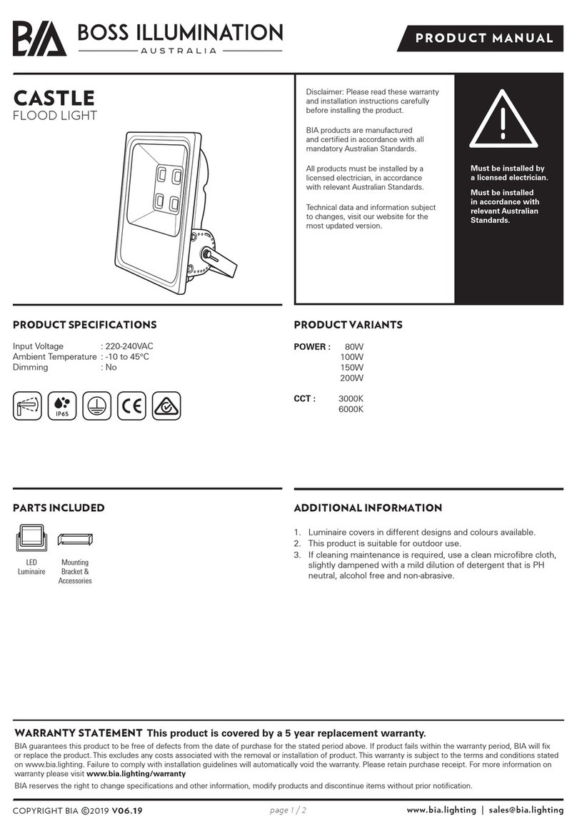
BOSS ILLUMINATION CASTLE Series product manual
Wetelux
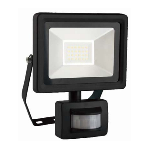
Wetelux 90 08 28 Original instructions
