SOLARJACK PCB-180 User manual

PCB-180
DC SUBMERISIBLE
PUMP CONTROLLER
USER’S MANUAL
12/07/99 1
PCB8-180C
SOLARJACK'S HIGH VOLTAGE PC SERIES PUMP CONTROLLERS
SOLARJACK'S PC series controllers are state-of-the-art solid state power converters designed as an
interface between a SOLARJACK pump and the DC power source. The purpose of this controller is to
maximize the total daily water output while providing protection for the pump as well as the power
source.
The unique features incorporated in this controller will protect the pump system insuring many years of
dependable, trouble free service. When used in a solar panel direct system it provides protection for the
pump from over-voltage and over- current conditions and will provide current boosting in low sunlight
conditions.
PCB8-180 SPECIFICATIONS
2 HP
Input Voltage 105-250V (Open Circuit)
(Eight Panels in Series Max)
Maximum Output Current 10 AMPS
Maximum Surge Current 14 AMPS
Maximum Output Power 1800 Watts (180V @ 10A)
FEATURES
1.) Current Boosting for matching the load requirements of the pump
2.) Voltage Regulation of the PV array around its’ maximum power point.
3.) Built in controller protection:
A. Output current limiting
B. Voltage surge protection
4.) Remote float switch circuit
5.) Low water cut-off circuit with adjustable set points
6.) High water cut-off circuit with adjustable set points
7.) Electrode logic reversal switch
Remote switch logic reversal switch

12/07/99 2
8.) Power in indicator light (Red)
Power out indicator light (Green)
Remote switch / electrode turn off indicator light (Amber)
9.) Fuse protection on the output
11.) Weathertight enclosure
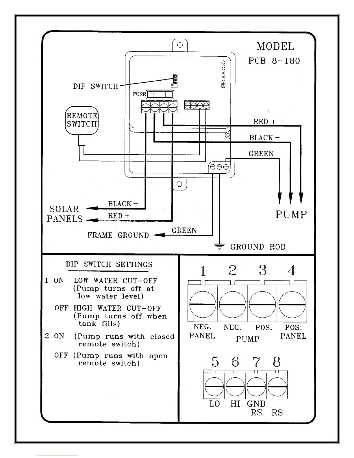
WIRING THE PCB-180 SERIES CONTROLLER
The PCB-180 Series controllers are limited to a maximum of twelve 17 volt panels connected in series
for the 180 volt systems. However, more panels may be connected in parallel.
This controller has a 4 position preset input voltage selector switch designed for various solar module
arrangements. Please refer to the selection chart for the switch position for your system.
CAUTION: Only one of the 4 preset switches should in the ON position at one time. These preset
voltage settings will work with the majority of the standard solar modules on the market. If you need to
change the voltage set point, the "panel voltage adjusting pot" will allow you to do so. (Refer to the
controller adjusting procedures). CAUTION: If you change the voltage setting using the adjusting
pot, it will change the set points on all 4 selector switches. It is highly recommended you do not
adjust this pot.
SELECTOR SWITCH SETTINGS
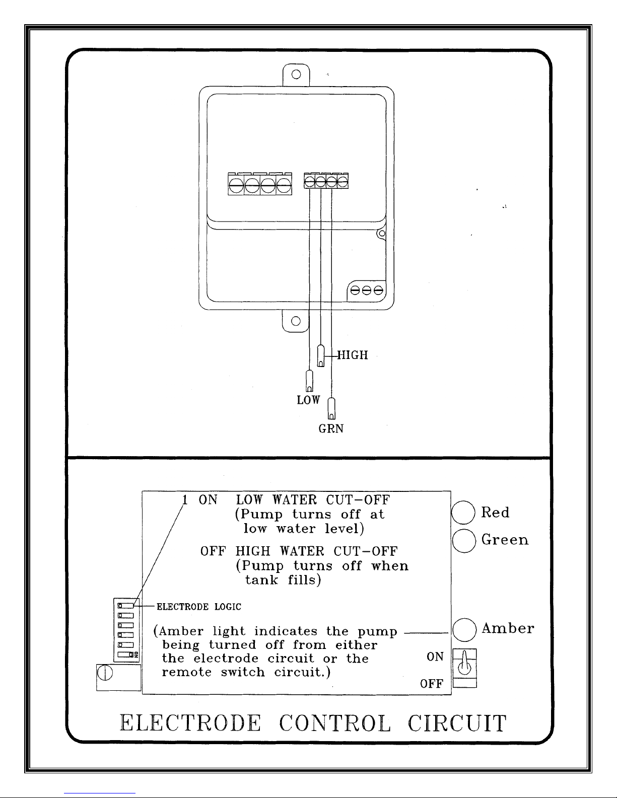
Switch Used For
1 Electrode Logic Off for High Water Cut-off
On for Low Water Cut-off
2 Remote Switch Logic Off-Make Contact for Turn-off
On-Break Contact for Turn-off
Switch Used For No. Series Modules Set Point
3 135 Volt Panel Direct 9 123 Volts
4 150 Volt Panel Direct 10 136 Volts
5 165 Volt Panel Direct 11 150 Volts
6 180 Volt Panel Direct 12 164 Volts

12/07/99 3
LARGE WIRE TERMINAL BLOCK
1 PV- NEGATIVE WIRE from the PV array.
2 LD- NEGATIVE WIRE to the pump or load
3 LD+ POSITIVE WIRE to the pump or load.
4 PV+ POSITIVE WIRE from the PV array.
SMALL WIRE TERMINAL BLOCK
5 LO LOW WATER ELECTRODE
6 HI HIGH WATER ELECTRODE
7 GRD/RS LOW WATER GROUND AND REMOTE SWITCH GROUND
REMOTE ON-OFF CIRCUIT is used to turn the pump on and off from a
remote location.
8 RS REMOTE SWITCH
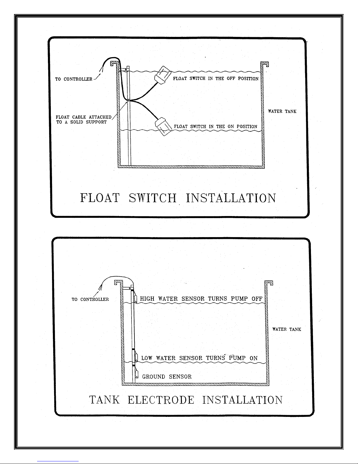
ELECTRODE CIRCUIT
Switch # 1 on the bottom dip switch is the electrode logic circuit. This circuit was designed to be used
with three electrodes. A high water, low water and ground electrode.
With switch #1 in the ON position it becomes a low water cut-off circuit (well). This keeps the pump
from running dry in a low yield well. The electrodes are generally attached to the drop pipe above the
pump in a well. When the water in the well draws down below the high water electrode the pump does
nothing. As it drops below the low water electrode it turns the pump off. As the water raises again and
passes the low water electrode the pump stays off. When it reaches the high water electrode it turns the
pump on again. This differential keeps the pump from rapid cycling.
It is recommended that the ground electrode be placed 2 inches above the pump, the low water electrode
be placed 2 inches above the ground electrode, and the high water electrode be placed from 2 to 5 feet
above the low water electrode depending upon the desired draw down.
As a general rule it is recommended that the low water electrode circuit be used only when absolutely
necessary. About 70% of the low water circuit systems work flawlessly and 30% seem to have problems.
Water with a high mineral content has a tendency to build up mineral deposits on the electrodes causing
false triggering. Cascading well water may create a current path between electrodes causing the pump to
stay running in low water conditions. Please be advised that this circuit does not work in all situations.
With switch #1 in the OFF position it becomes a high water cut-off circuit (tank fill). This keeps a
storage tank from over-flowing. The electrodes are generally taped together and dropped into a tank. A
small pipe or rod can be installed in the tank and the electrodes can then be taped to the pipe or rod.
When the water in the tank draws down below the high water electrode it does nothing. As it drops
below the low water electrode it turns the pump on. As the water raises again and passes the low water
electrode the pump stays on. When it reaches the high water electrode it turns the pump off again.
12/07/99 4
It is recommended that the ground electrode be placed 2 inches above bottom of the tank or the ground
wire can be attached to the tank if the tank is metal. The low water electrode should be placed at the
desired turn-on point and the high water electrode should be placed at the desired turn-off point.
REMOTE SWITCH CIRCUIT
The purpose of the remote switch circuit is to turn the pump on and off from a distant location without
having to switch the main power lines from the solar modules to the pump. This circuit uses a low
voltage, micro-amp circuit to bias the FET in the controller. This low power switching circuit allows the
use of small gauge wire to run over a thousand feet to control the pump.
Since this is such a sensitive circuit it requires the use of a high quality, shielded, two conductor cable.
The shield over the wires should then be attached to the ground terminal in the controller. This in turn is
attached to a ground rod.
Switch #2 in the ON position allows the pump to run when terminals 7 and 8 are connected. This is
generally used in conjunction with a float switch or a pressure switch which makes contact to run the
pump.
Switch #2 in the OFF position allows the pump to run when terminals 7 and 8 are disconnected.
This is generally used in conjunction with a float switch which breaks contact to make the pump run.
CONTROLLER ADJUSTING PROCEDURE
CAUTION:. A QUALIFIED SOLAR ELECTRIC TECHNICIAN SHOULD ONLY PERFORM
THIS PROCEDURE. THIS PROCEDURE IS NOT NECESSARY IF STANDARD 16.5 TO 17
VOLT SOLAR MODULES ARE BEING USED.
This procedure will not work on a centrifugal type pump such as an SCS submersible. It is only
for positive displacement type pumps.
The purpose of this procedure is to adjust the voltage of the PV array to its peak power point and thus
obtain the maximum water delivery from the pump. This procedure should be performed with the panels
at their normal operating temperature at mid-day.
(option 1) For Panel voltage adjustment at the maximum Power Point.
1. With the system installed and pumping water, turn the panels away from the sun until the pump
flow rate is reduced by approximately 50%. If this is not-possible, then shade the panels slightly
until you obtain the same results. This puts the controller in a current boosting mode so this
adjustment can be made.
2. Connect a DC volt meter to the pump side of the controller. (LD+ and LD-)
3. Turn the small brass adjusting screw on the "Panel Voltage Adjusting Pot", located on the front of
the controller, until the highest possible voltage is obtained. (If this controller is used on a Jack
Pump system using a flywheel there will be a slight delay from the time you make an adjustment to
when a change in voltage will be noticed.)

12/07/99 5
4. Return the panels to their normal position. The pump will then operate at its maximum output.
(Option 2) For estimated panel voltage adjustment.
1. With the system installed and pumping water, turn the panels away from the sun until the pump
flow rate is reduced by approximately 50%. If this is not possible, then shade the panels slightly
until you obtain the same results. This puts the controller in a current boosting mode so this
adjustment can be made.
2. Connect a DC volt meter to the panel side of the controller. (PV+ and PV-)
3. Estimate the proper voltage by multiplying the voltage rating of the panel’s times the number of
panels connected in series and deduct 20%.
Example:
12-80 Watt panels @ 17.1 Volts ea. = 205 Volts – 20% = 164 Volts
4. Turn the small brass adjusting screw on the "Panel Voltage Adjusting Pot", located on the front of
the controller, until the estimated voltage is obtained.
5. Return the panels to their normal position. The pump will then operate at its maximum output.

12/07/99 6
TROUBLESHOOTING
PUMP DOES NOT RUN
If the pump does not run, first make sure the on/off switch is in the up position. Then look at the
row of lights to check the status of the system. The red light (indicating power in) and the green
light (indicating power out) are the only ones that should be on. All other lights indicate that the
controller has been turned off for a specific reason.
1. Check wiring diagrams for proper connections. If the solar panel wires are connected in reverse
polarity the controller will short to ground. CAUTION: If a battery system or a high amperage panel
system is used and the polarity is reversed, damage to the controller will result. This is not covered
under warranty.
If the motor polarity is reversed on a brush type motor the motor will simply run backwards. If the
polarity is reversed on an SCS brushless DC motor, a diode in the motor will block any current flow. The
result would be an open circuit and this will not damage the motor.
2. Check for proper panel and controller voltage and current. If a DC volt and amp meter is
available, the best way to test f or proper power is to check input voltage and current and output voltage
and current. This will indicate where to start looking for the problem.
If a volt and amp meter is not available then a quick look at the indicator lights will verify voltage coming
from the panels going to the controller (red) and power from the controller going to the pump (green) .
The other three lights will also indicate the controller being turned off for low voltage (yellow),
over-current (orange) or a remote switch turn-off (amber).
If the red light is on and all other lights are off take a DC volt meter and check for the correct open
circuit voltage . Typical open circuit voltage ranges from 18 to 20 volts per panel. Multiply this times the
number of panels wired in series. Check to see if this calculated voltage corresponds to the measured
voltage.
For an array short circuit current test, disconnect the array wires from the controller and short the wires
together through a DC amp meter. Check this current against the short circuit current rating of the solar
panels. The current in a series string should be the same as the rating for a single panel. If the current in a
string is low, run the same test for each individual panel to identify the defective one.
3. Check for proper Panel voltage set point. Make sure the proper panel voltage selector switch is on
for your panel arrangement. (Switches 4-6 on the bottom dip switch.) Note: If the incoming voltage is
lower than the set point voltage, the controller will not turn on.

12/07/99 7
IF THE RED AND GREEN LIGHTS ARE ON, WITH ALL OTHER LIGHTS OFF AND THE
PUMP DOES NOT RUN: (IN GOOD SUNLIGHT)
4. Check for proper controller output voltage. Connect a DC volt meter across terminals 2 (LD-) and
3 (LD+) on the large terminal block. If no voltage is indicated check the fuse. If the fuse is good and
there is no voltage on the output, the controller has an internal problem and must be sent back to the
factory for repairs.
If the voltage on the output terminals is about the same as the open circuit voltage, then check for an
open circuit between the controller and the pump motor. Check the wiring and the wire splice. If there is
open circuit voltage on the pump side of the splice and the motor does not run, then there is an open
circuit in the motor. This indicates the motor has an internal problem and must be sent back to the factory
for repairs.
If the voltage on the output terminals is very low, disconnect the pump wires and check again. If the
voltage goes to open circuit, a high current load is indicated. Usually a high load will trigger the
over-current circuit and will turn the controller off and at the same time turn the orange light on. To reset
this circuit turn the on/off switch off and back on again
5. Testing an SCS Brushless DC Motor.
To check an SCS Brushless DC motor, take an ohm meter and set to a meg-ohm scale. Connect the
negative lead on the meter to the positive lead on the motor and the positive lead on the meter to the
negative lead on the motor. The reading should be over 10 meg-ohms if measuring through the drop wire
with the motor in the well. If measuring a dry motor only at the surface it should read over 100
meg-ohms. This test is for the polarity protection diode.
To check the FETS connect the positive meter lead to the positive motor lead and the negative meter
lead to the negative motor lead. If the FETS are shorted to ground the meter will read around 2000 to
5000 ohms and steady. If they are not shorted it will read about 1 to 5 meg-ohms at first and as the
internal capacitor charges it will drift higher.
12/07/99 8

12/07/99 9
12/07/99 10
12/07/99 11

12/07/99 12

12/07/99 13
6RODUMDFNV/LPLWHG:DUUDQW\
PCA and PCB Controllers
LIMITED WARRANTY – TWENTY-FOUR MONTHS
SOLARJACK warrants the product to be free from defects in materials and workmanship
under normal applications and service conditions for TWENTY-FOUR (24) months from
date of sale to the original purchaser, but not to exceed (30) months from the date
of manufacture. SOLARJACK will, at its option, either repair or replace the product
if it fails due to a defect in material or workmanship during the period of this
warranty.
This warranty is extended only to the original purchaser. A completed warranty card
with the pump serial number and the controller serial number must be on file at the
factory to validate the warranty. No warranty performances will he rendered without
a valid warranty card on file at the SOLARJACK factory.
This warranty only covers failures due to defects in materials or workmanship that
occur during normal use. It does not cover damage which occurs in shipment, or
failures which are caused by products not supplied by SOLARJACK or failures which
result from accident, misuse, abuse, neglect, mishandling, misapplication,
alteration, modification or repairs by anyone other than SOLARJACK, or damage that
is attributable to acts of God. Any disassembly whatsoever of the product voids all
warranty.
Warranty limitations
There are no express warranties except as listed above. SOLARJACK shall have no
responsibility for damage to property, persons, animals, or other loss or injury
resulting from the use of this product.
UNDER NO CIRCUMDSTANCES WILL SOLARJACK BE LIABLE FOR ANY INCIDENTAL OR CONSEQUENTIAL
DAMAGE, UNLESS OTHERWISE EXPRRESSLY STATED HEREIN. ALL PRODUCTS ARE SOLD AS IS WITH
ALL FAULTS.
Any warranties are limited to the warranty period described above. SOLARJACK’S
maximum liability under any warranty, expressed, or implied, or statutory, is
limited to the purchase price of the product. The purchaser's exclusive remedy shall
be only as stated herein. This warranty is in lieu of all other warranties expressed
or implied. This warranty gives you specific rights; your state law may provide for
additional rights or may affect the time and other limitations set forth herein.
This Warranty Excludes: Labor, transportation and related costs incurred by the
consumer to make the allegedly defective equipment available to the factory for
inspection, re-installation, costs caused by interruption of service, or lost
profits.
If a problem with the product develops during the warranty period, you may contact
your dealer. If the problem is not handled to your satisfaction, contact:
Kyocera Solar, Inc./ SOLARJACK, 7812 E. Acoma Drive, Scottsdale, AZ 85260
Telephone (800) 223-9580 FAX (480) 483-6431
www.kyocerasolar.com
This manual suits for next models
1
Table of contents
Popular Media Converter manuals by other brands

QSI
QSI Quantum Electric Q1a Operation manual

OT Systems
OT Systems FT210CB Series Installation and operation manual

SIIG
SIIG CE-H23L11-S1 quick start guide

HEIDENHAIN
HEIDENHAIN LC 2x1 Replacing Instructions

Avenview
Avenview SW-HVD-HDMA-4X1 user guide

Baumer
Baumer HOG 11 Mounting and operating instructions


