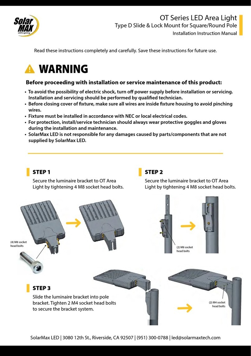
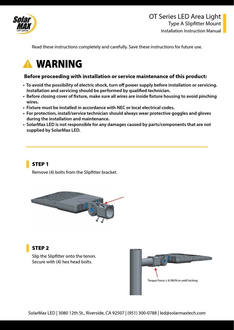
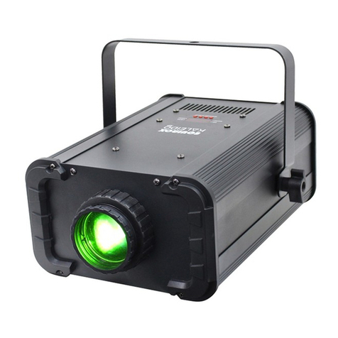
SolarMax iE Series User manual
Other SolarMax Lighting Equipment manuals
Popular Lighting Equipment manuals by other brands
Harbor Freight Tools
Harbor Freight Tools luminar EVERYDAY 59575 Owner's manual & safety instructions
MAC TOOLS
MAC TOOLS SPL2500M instruction manual
MONTEAUX
MONTEAUX 1507203P1 Use and care guide
Shadow-Caster
Shadow-Caster SCM-LC-N2K Installation & operation manual
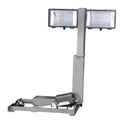
Command Light
Command Light SHADOW Series user guide
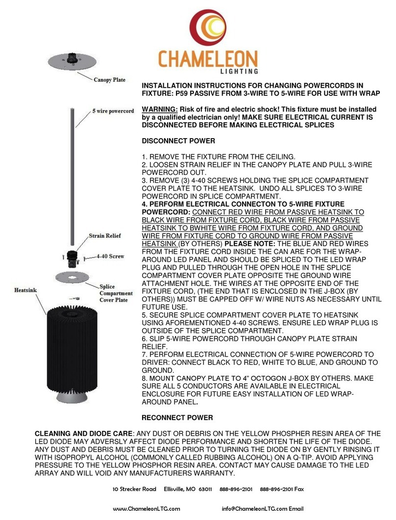
Chameleon Lighting
Chameleon Lighting P59 Installation instruction
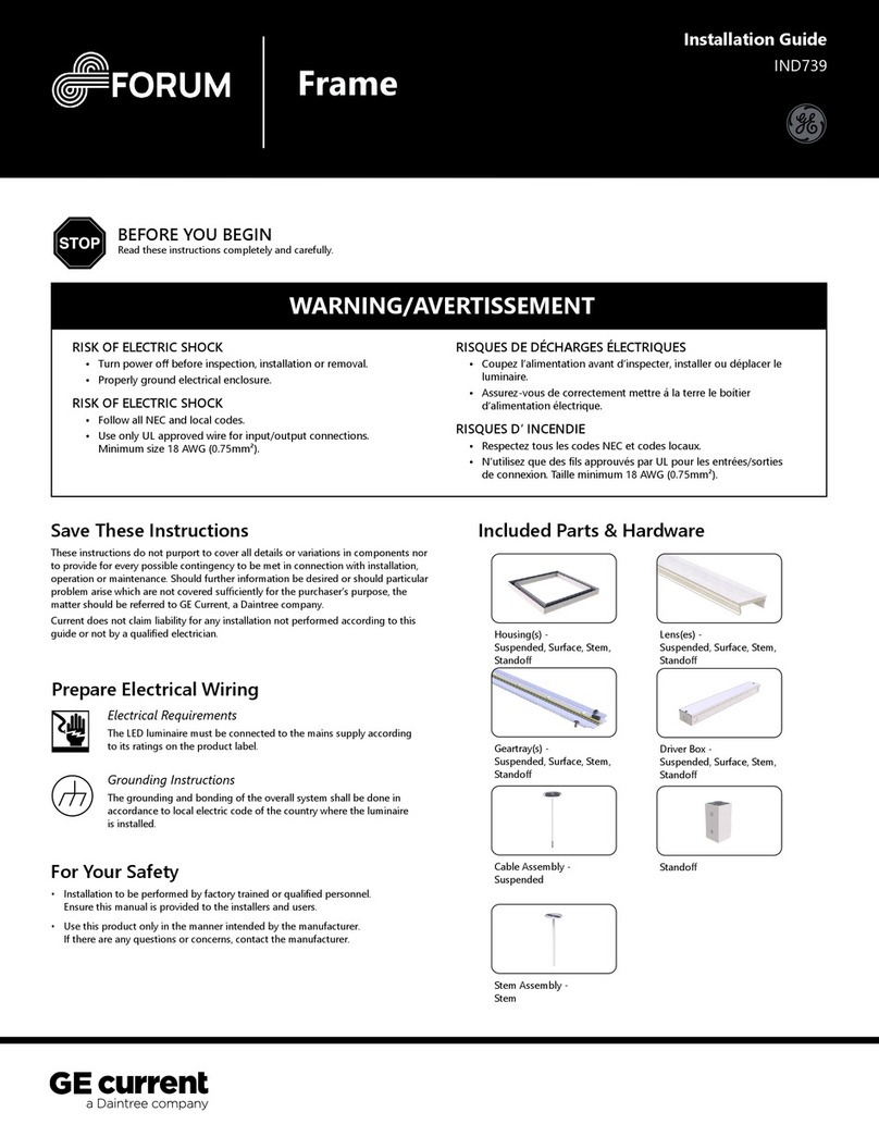
Daintree
Daintree GE Forum Frame IND739 installation guide
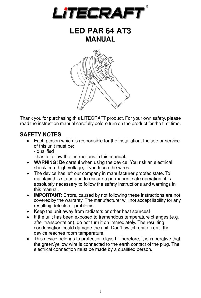
Litecraft
Litecraft LED PAR 64 AT3 instruction manual
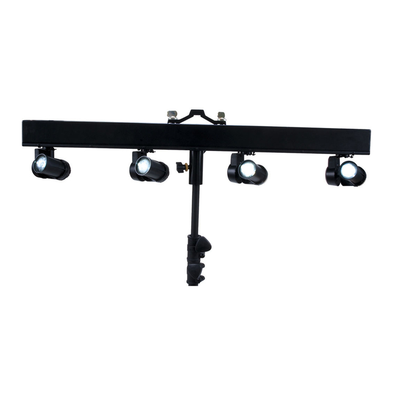
Elation
Elation EVENT BAR User instructions
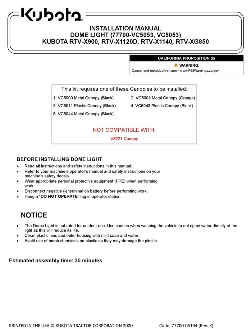
Kubota
Kubota 77700-VC5053 installation manual
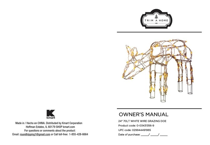
Trim a Home
Trim a Home M16(24)-70L owner's manual

Zodiac
Zodiac PH Expert Instructions for installation and use


