manuals.online logo
Brands
  1. Home
  2. •
  3. Brands
  4. •
  5. Daintree
  6. •
  7. Lighting Equipment
  8. •
  9. Daintree GE Forum Frame IND739 User manual

Daintree GE Forum Frame IND739 User manual

Installation Guide
IND739
BEFORE YOU BEGIN
Read these instructions completely and carefully.
WARNING/AVERTISSEMENT
RISK OF ELECTRIC SHOCK
• Turn power o before inspection, installation or removal.
• Properly ground electrical enclosure.
RISK OF ELECTRIC SHOCK
• Follow all NEC and local codes.
• Use only UL approved wire for input/output connections.
Minimum size 18 AWG (0.75mm²).
RISQUES DE DÉCHARGES ÉLECTRIQUES
• Coupez l’alimentation avant d’inspecter, installer ou déplacer le
luminaire.
• Assurez-vous de correctement mettre á la terre le boítier
d’alimentation électrique.
RISQUES D’ INCENDIE
• Respectez tous les codes NEC et codes locaux.
• N’utilisez que des ls approuvés par UL pour les entrées/sorties
de connexion. Taille minimum 18 AWG (0.75mm²).
Frame
WARNING/AVERTISSEMENT
Save These Instructions
These instructions do not purport to cover all details or variations in components nor
to provide for every possible contingency to be met in connection with installation,
operation or maintenance. Should further information be desired or should particular
problem arise which are not covered suciently for the purchaser’s purpose, the
matter should be referred to GE Current, a Daintree company.
Current does not claim liability for any installation not performed according to this
guide or not by a qualied electrician.
Included Parts & Hardware
For Your Safety
• Installation to be performed by factory trained or qualied personnel.
Ensure this manual is provided to the installers and users.
• Use this product only in the manner intended by the manufacturer.
If there are any questions or concerns, contact the manufacturer.
Prepare Electrical Wiring
Electrical Requirements
The LED luminaire must be connected to the mains supply according
to its ratings on the product label.
Grounding Instructions
The grounding and bonding of the overall system shall be done in
accordance to local electric code of the country where the luminaire
is installed.
Housing(s) -
Suspended, Surface, Stem,
Stando
Cable Assembly -
Suspended
Stem Assembly -
Stem
Driver Box -
Suspended, Surface, Stem,
Stando
Stando
Geartray(s) -
Suspended, Surface, Stem,
Stando
Lens(es) -
Suspended, Surface, Stem,
Stando
2
Forum | Frame Series | Surface Mounting Installation Guide
Installation
Mount remote driver box to structure with in 50’ from xture. Run
wires from driver box to xture.
1
2Align xture housing ush to ceiling or wall depending what has been
specied and secure through factory-drilled holes using screws (not
provided) appropriate for surface type.
Turn o the power to the xture’s circuit. 7/8” power feed hole is
provided for wiring to be fed into xture.
Connect geartray to xture housing via provided electrical junction and
re-insert geartray and lens back into housing.
34
COMPONENTS FOR SURFACE MOUNTING
The Frame series surface mounting system consists of four main
components: the housing (A), the geartray (B), the lens (C), the remote
drive box (D). These items come shipped with and attached to the
xture to help ensure proper counts and clarication during assembly.
In preparation for installation, remove geartray (B) and lens (C) from
housing (A) and set aside in a safe area.
A
B
C
D
3
Forum | Frame Series | Suspended Mounting Installation Guide
Installation
Mount remote driver box to structure within 50’ from xture. Run
positive wire to rst junction box and negative wire to second junction
box to make conductive cable connection. If xture is hung by conical
cables bring both positive and negatives wires to the same junction
box.
1
Turn o the power to the xture’s circuit. With the xture
supported in the air, raise the cable assemblies to their
corresponding junction boxes, thread the conductive cable (A)
through the canopy (B), cross bar (C), and respective components
(D). Apply heat shrink (E) to the exposed conductive cable and
connect the power feed from the ceiling side to the conductive cable
via quick connect (F).
Install the junction box cross bar, slide canopy up into place and
thread on remaining hardware to hold the canopy in place. Follow
governing electrical code for making your connections in the
junction box.
With xture now mounted, you can slowly lower it into place. Fine
adjustments to height and leveling can be made at the
gripper assemblies located on the upper surface of the xture.
2
3
COMPONENTS FOR SUSPENDED MOUNTING
The Frame series cable mounting system consists of two main
components: the power feed assemblies (A) and the remote mount
driver box (B). Both items come shipped with the xture to help ensure
proper counts and clarication during assembly.
In preparation of installation, ensure that crossbars, canopy covers,
cable grippers and cord grips are all accounted for. The cable mounting
system utilizes conductive suspension cables to be used with a standard
j-box for each cable. Be sure to follow all governing code related to
wiring, structural integrity, and use of materials.
B
A
A
D
B
C
E
F
A
4
Forum | Frame Series | Stem Mounting Installation Guide
Installation
Mount remote driver box to structure with in 50’ from xture. Run
wires from driver box to junction box.
1
2Thread xture wires through stem, canopy, cross bar, and thread
stem into xture.
Turn o the power to the xture’s circuit. Support the xture
at the junction box and connect the wires from the xture to the
junction box.
Mount cross bar to junction box and lift canopy and lock nut into place.
34
COMPONENTS FOR STEM MOUNTING
The Frame series stem mounting system consists of two main
components: the stem canopy assemblies (A) and the remote mount
driver box (B). Both items come shipped with the xture to help ensure
proper counts and clarication during assembly.
In preparation of installation, ensure that crossbars, canopy covers,
and stems are all accounted for. Be sure to follow all governing code
related to wiring, structural integrity, and use of materials.
A
A
B
5
Forum | Frame Series | Stando Mounting Installation Guide
Installation
Mount remote driver box to structure with in 50’ from xture.
Run wires from driver box to xture.
1
2Mount rst bracket from stando to mounting surface with
appropriate hardware, provided by installing contractor. Note stand o
mount hole to face the inside of the xture.
COMPONENTS FOR STANDOFF MOUNTING
The Frame series stando mounting system consists of two main
components: the stando assembly (A) and the remote mount
driver box (B). Both items come shipped with the xture to help
ensure proper counts and clarication during assembly.
In preparation of installation, ensure that stand os and stando
mounting brackets are all accounted for. Be sure to follow all
governing code related to wiring, structural integrity, and use of
materials.
A
A
B
Mount second bracket from stando to xture with hardware
provided by factory. Note stand o mount hole to face the inside of
the xture.
Turn o the power to the xture’s circuit. Support the xture at
the surface side brackets and connect the wires from the mounting
surface to the xture.
34
www.gecurrent.com
© 2021 Current Lighting Solutions, LLC. All rights reserved. GE and the GE monogram are trademarks of the
General Electric Company and are used under license. Information provided is subject to change without
notice. All values are design or typical values when measured under laboratory conditions.
IND739 (Rev 12/13/2021)
Forum | Frame Series | Stando Mounting Installation Guide
Installation
Slide standos onto surface side brackets and screw into place.
Next slide xture side brackets onto standos and screw xture
in place.
5
This device complies with Part 15 of the FCC Rules. Operation is subject to the following two conditions: (1) This device may not cause harmful interference, and (2) this device
must accept any interference received, including interference that may cause undesired operation. CAN ICES-005 (A) / NMB-005 (A)
Note: This equipment has been tested and found to comply with the limits for a Class A digital device, pursuant to part 15 of the FCC Rules. These limits are designed to
provide reasonable protection against harmful interference when the equipment is operated in a commercial environment. This equipment generates, uses, and can radiate
radio frequency energy and, if not installed and used in accordance with the instruction manual, may cause harmful interference to radio communications. Operation of this
equipment in a residential area is likely to cause harmful interference in which case the user will be required to correct the interference at their own expense.

Other Daintree Lighting Equipment manuals
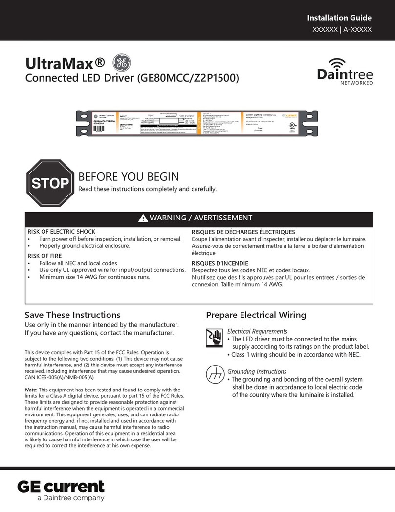
Daintree GE Tetra MAX User manual

Daintree

Daintree GE Tetra MAX User manual

Daintree GE current Proline LEX Series User manual

Daintree

Daintree GE current Proline LEX Series User manual

Daintree GE Current RAIL159 User manual

Daintree

Daintree GE Current RAIL159 User manual

Daintree GE cirrent Tetra Rigid Light Bar User manual

Daintree

Daintree GE cirrent Tetra Rigid Light Bar User manual

Daintree GE current Tetra Contour User manual

Daintree

Daintree GE current Tetra Contour User manual

Daintree Contour Gen 2 Flex User manual

Daintree

Daintree Contour Gen 2 Flex User manual

Daintree GE current Immersion GELP24-100U-GLX User manual

Daintree

Daintree GE current Immersion GELP24-100U-GLX User manual

Daintree GE current Tetra GETP35-2 User manual

Daintree

Daintree GE current Tetra GETP35-2 User manual

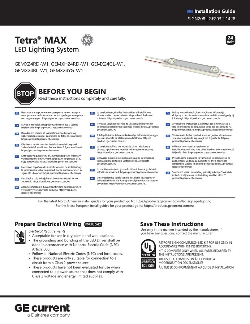
Daintree GE Current UltraMax GED80MCC/Z2P1500 User manual
Daintree

Daintree GE Current UltraMax GED80MCC/Z2P1500 User manual

Daintree GE Current Lumination LRXD Series User manual

Daintree

Daintree GE Current Lumination LRXD Series User manual

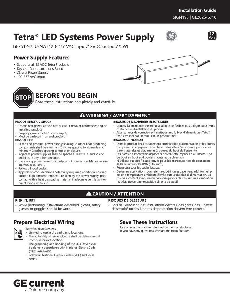
Daintree GE Current Tetra GEPS12-25U-NA User manual

Daintree

Daintree GE Current Tetra GEPS12-25U-NA User manual

Daintree GE Tetra miniMAX User manual

Daintree

Daintree GE Tetra miniMAX User manual

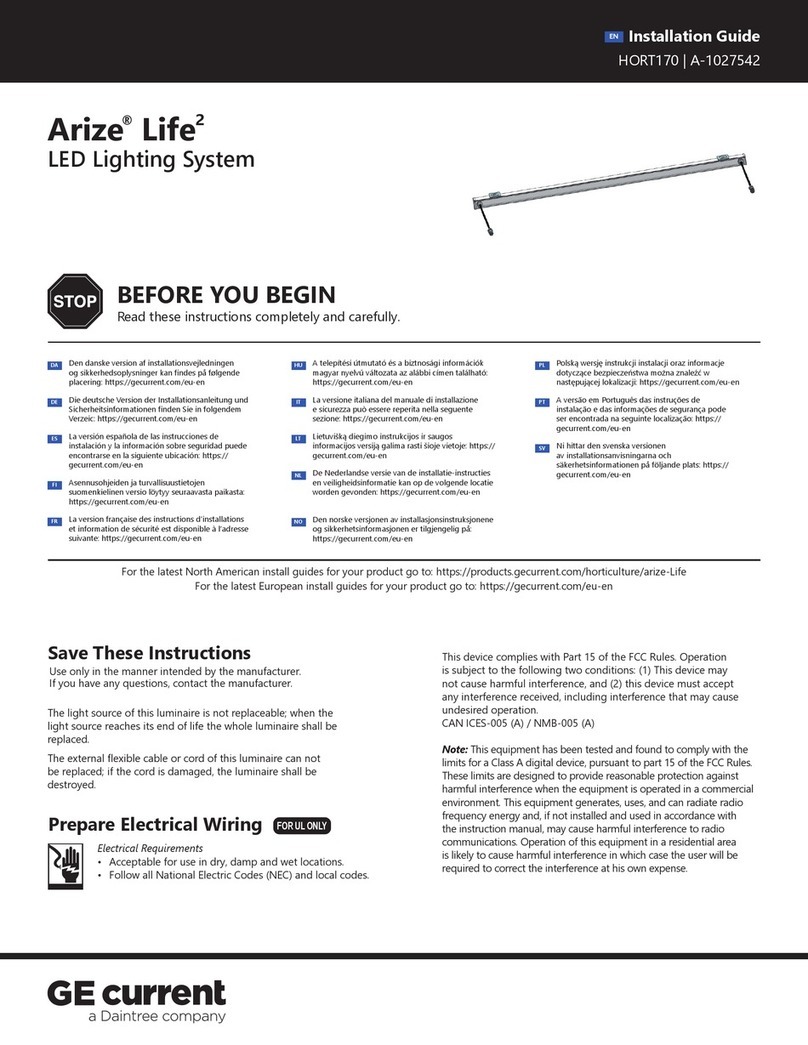
Daintree GE Current Arize Life2 User manual

Daintree

Daintree GE Current Arize Life2 User manual

Daintree GE Current Tetra GEPS24-25U-NA User manual

Daintree

Daintree GE Current Tetra GEPS24-25U-NA User manual

Daintree GE current Lumination RC Series User manual

Daintree

Daintree GE current Lumination RC Series User manual

Daintree GE current Evolve EFC1 Series User manual

Daintree

Daintree GE current Evolve EFC1 Series User manual

Daintree RM4 User manual

Daintree

Daintree RM4 User manual

Daintree GE current Tetra PowerStrip Snap DS User manual

Daintree

Daintree GE current Tetra PowerStrip Snap DS User manual

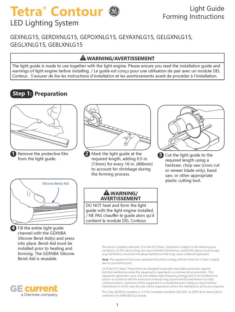
Daintree GE GEXNLG15 User manual

Daintree

Daintree GE GEXNLG15 User manual

Daintree GE Current Arize Factor User manual

Daintree

Daintree GE Current Arize Factor User manual

Daintree GE current Tetra PowerStrip DS User manual
Daintree

Daintree GE current Tetra PowerStrip DS User manual

Daintree GE current Lumination LRX Series User manual
Daintree

Daintree GE current Lumination LRX Series User manual

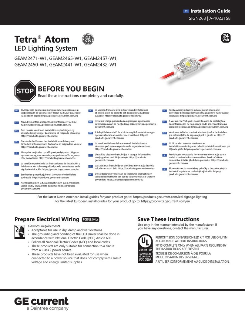
Daintree GE Tetra Atom User manual

Daintree

Daintree GE Tetra Atom User manual
Popular Lighting Equipment manuals by other brands

Fabbian CUBETTO instructions

Fabbian

Fabbian CUBETTO instructions

Natec ALFAMA user manual

Natec

Natec ALFAMA user manual

Future light Pro-Head-Spot PHS-260 user manual

Future light

Future light Pro-Head-Spot PHS-260 user manual

Larson Electronics FRL-4P-S1-60-1X-T5HO-130W-UVC instruction manual

Larson Electronics

Larson Electronics FRL-4P-S1-60-1X-T5HO-130W-UVC instruction manual

Elecro Engineering QUANTUM CLASSIC Q-65 Installation & operating manual

Elecro Engineering

Elecro Engineering QUANTUM CLASSIC Q-65 Installation & operating manual

Quoizel NAO1507EK installation guide

Quoizel

Quoizel NAO1507EK installation guide

Cooper Lighting Halo Lazer LZR330 Specification sheet

Cooper Lighting

Cooper Lighting Halo Lazer LZR330 Specification sheet

Ledj LED RGB 252 user manual

Ledj

Ledj LED RGB 252 user manual

Whelen Engineering Company 508 Series installation guide

Whelen Engineering Company

Whelen Engineering Company 508 Series installation guide

Eterna MSCSLEDCR installation instructions

Eterna

Eterna MSCSLEDCR installation instructions

S-Lighting S-BLINDER user manual

S-Lighting

S-Lighting S-BLINDER user manual

hillvert HT-WEDGE-50 user manual

hillvert

hillvert HT-WEDGE-50 user manual

Lumencor PEKA instruction manual

Lumencor

Lumencor PEKA instruction manual

DS Produkte 66165 instructions

DS Produkte

DS Produkte 66165 instructions

Lightolier PowerArc CANOPY FIXTURE Instructions for installation

Lightolier

Lightolier PowerArc CANOPY FIXTURE Instructions for installation

Hess LEDIA LL ID EL Series Installation and operating instructions

Hess

Hess LEDIA LL ID EL Series Installation and operating instructions

Viabizzuno trasparenza parete 100 Installing instructions

Viabizzuno

Viabizzuno trasparenza parete 100 Installing instructions

Ferplast EXPLORALIGHT Series user manual

Ferplast

Ferplast EXPLORALIGHT Series user manual

manuals.online logo
manuals.online logoBrands
  • About & Mission
  • Contact us
  • Privacy Policy
  • Terms and Conditions

Copyright 2025 Manuals.Online. All Rights Reserved.