Shadow-Caster SCM-LC-N2K User manual
WWW.SHADOW-CASTER.COM
INSTALLATION & OPERATION MANUAL
LIGHT COMMANDER
SCM-LC-N2K NMEA 2000
SCM-LC-N2K-PLUS NMEA 2000 + Ethernet

Shadow-Caster™ LED Lighting | 2060 Calumet Street. | Clearwater, FL 33765
p: 1+ 727.474.2877 e: info@shadow-caster.com w: shadow-caster.com
2
TABLE OF CONTENTS
LIGHT COMMANDER BOX CONTENTS ..........................................................................................................................
LIGHT COMMANDER OVERVIEW ..................................................................................................................................
LIGHT COMMANDER FEATURES ..................................................................................................................................
SCM-LC-N2K TYPICAL WIRING DIAGRAM ....................................................................................................................
SCM-LC-N2K-PLUS TYPICAL WIRING DIAGRAM ..........................................................................................................
CONNECTING TWO LIGHT COMMANDERS TYPICAL WIRING DIAGRAM ....................................................................
DEUTSCH CONNECTORS FOR LIGHTING AND SWITCH INPUTS.................................................................................
INSTALLATION ...............................................................................................................................................................
SWITCH INPUTS (OPTIONAL)........................................................................................................................................
ADDING ADDITIONAL REMOTES AND MULTI-FUNCTION DISPLAYS ..........................................................................
SHADOW-NET™ DEVICES ...............................................................................................................................................
OPTIONAL PARTS ...........................................................................................................................................................
CONNECTING STEREO INPUT FOR STEREO MUSIC SYNC INPUT ..............................................................................
BEST PRACTICES FOR MITIGATING NOISE ISSUES ....................................................................................................
BASIC OPERATIONS FOR SHADOW-CASTER MFD USER INTERFACE.........................................................................
BASIC OPERATIONS FOR SIMRAD NMEA 2000 LIGHTING INTERFACE CONFIGURING ZONES................................
TROUBLESHOOTING ......................................................................................................................................................
DIMENSIONS ..................................................................................................................................................................
3
3
3
4
5
6
7
8
9
9
9
9
10
10
11
15
18
18
LIGHT COMMANDER
INSTALLATION & OPERATION MANUAL

LIGHT COMMANDER BOX CONTENTS
•SCM-LC-N2K or SCM-LC-N2K-PLUS Light Commander
•4 x SS316 Pan Head #8 x 3⁄4" Mounting Screws
•Warranty and Registration Information
•Deutsch connector pigtail assemblies
•Standard Ethernet Cable (Plus ONLY)
PRODUCT SERIAL NUMBER
You can add your product serial number here for
warranty and product registration purposes.
The serial number is located on the back of the
Light Commander housing and on the packaging.
My Serial Number:
3
Designed & Manufactured
in Clearwater, FL
© 2021 Shadow-Caster™ LED Lighting, All Rights Reserved
LIGHT COMMANDER OVERVIEW
The Shadow-Caster™ Light Commander (SCM-LC) is
available in two models:
SCM-LC-N2K
For connection directly to MFDs with built in NMEA
2000 lighting support, or as an expansion model to
"Light Commander N2K PLUS" installations.
SCM-LC-N2K-PLUS
Offers an integrated Ethernet interface along with
an NMEA 2000 interface for network connections to
Garmin, Simrad, Lowrance, B&G, Raymarine, Furuno and
Humminbird.
This installation and operation manual covers both
SCM-LC-N2K and SCM-LC-N2K-PLUS models.
SCM-LC-N2K FEATURES
• Control up to 6 zones lights (expandable to 12 or 18
by adding one or two SCM-LC-N2K for 6 additional
channels each).
• IP67 housing with LED indicators for channels 1-4 and
logo backlight.
• Full independent color, brightness and multiple
lighting modes including 4 types of music
synchronization, fade and custom color rotations.
• Built in support for 4 channels of RGBW lighting up to
15 amps each.
• Digital overcurrent protection.
• Auto-detect for selection of RGB or RGBW channel
congurations.
• Store and recall virtually unlimited lighting scenes.
• Integrated push button switch support. Control ON/
OFF and brightness for each of the 6 zones.
• Global momentary push button color control.
• Deutsch connectors for lighting connections and
switch inputs.
• Direct music input via 3.5mm audio jack.
SCM-LC-N2K-PLUS FEATURES
All the features listed above for the SCM-LC-N2K, plus:
• Ethernet port for MFD Ethernet connection to use the
Shadow-Caster™ full lighting control interface.
• USB-C port for software upgrades
LIGHT COMMANDER
INSTALLATION & OPERATION MANUAL
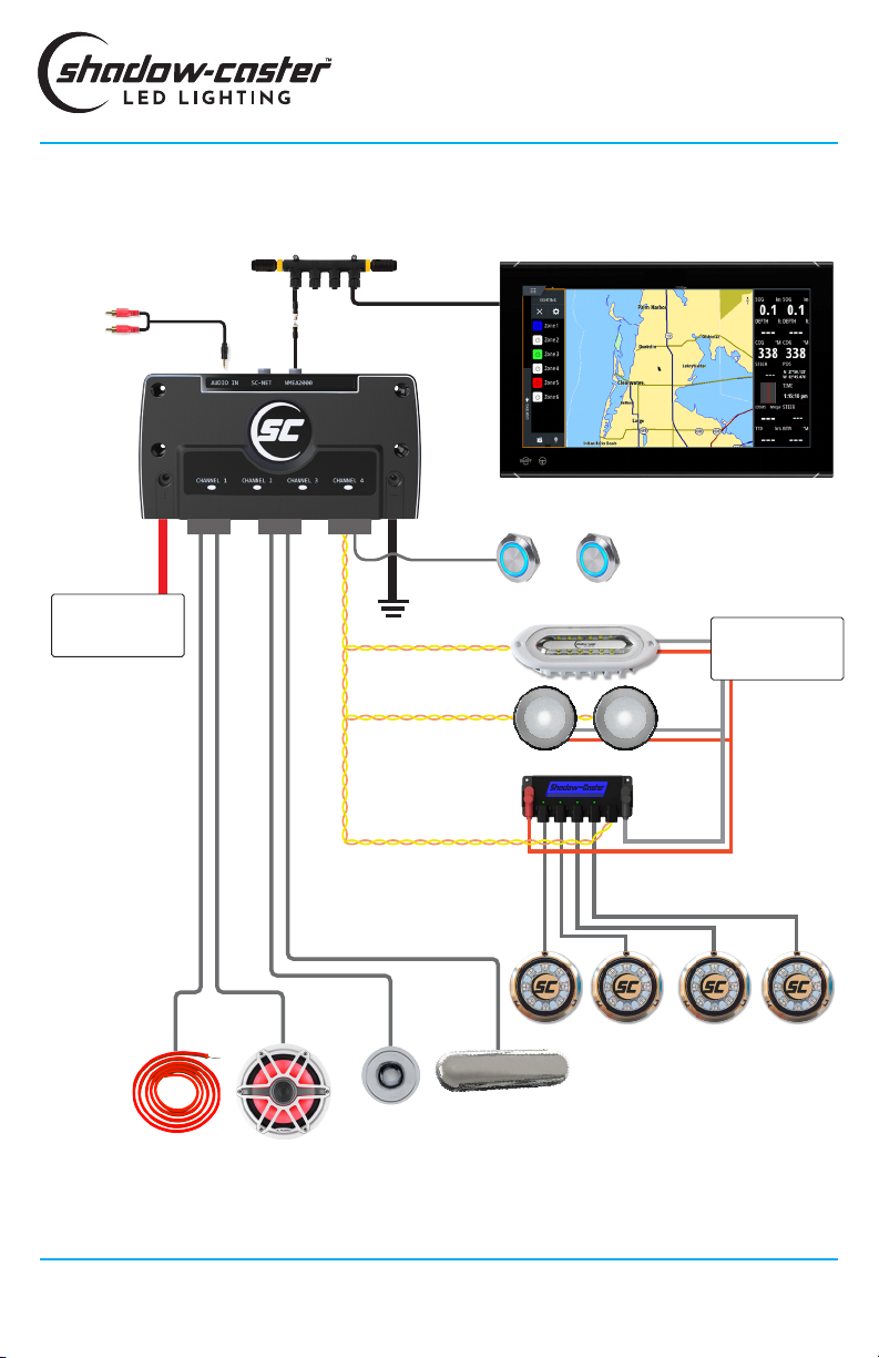
10-30V
Power Source
Shadow-NET™
Optional Push Button Switches
Up to 6 switches can be connected to
control RGB(W) Zones 1-6.
In addition a control switch can also
be connected for ‘next color’ and ‘color
rotation’ control.
Light Commander
SCM-LC-N2K
3.5mm Female
Audio Jack
Connector 3Connector 1 Connector 2
GND
SCM-PD4CH
10-30V
Power Source
Multi-Function Display
NMEA 2000 Backbone
SCM-LC-N2K TYPICAL WIRING DIAGRAM
Shadow-Caster™ LED Lighting | 2060 Calumet Street. | Clearwater, FL 33765
p: 1+ 727.474.2877 e: info@shadow-caster.com w: shadow-caster.com
4
GND
Note:
For connector 1-3
pin congurations
see page 7
4 x channels of RGB(W) lighting
(supports up to 15A per channel)
LIGHT COMMANDER
INSTALLATION & OPERATION MANUAL
Simrad side bar lighting control interface
Zone 1 Zone 6
...
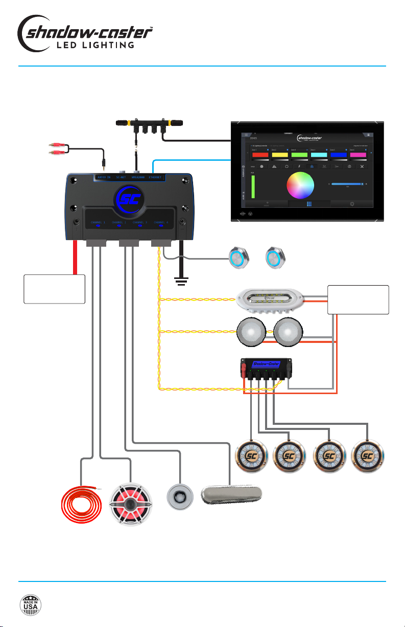
10-30V
Power Source
Shadow-NET™
Optional Push Button Switches
Up to 6 switches can be connected to
control RGB(W) Zones 1-6.
In addition a control switch can also
be connected for ‘next color’ and ‘color
rotation’ control.
Light Commander
SCM-LC-N2K-PLUS
3.5mm Female
Audio Jack
Connector 3Connector 1 Connector 2
GND
SCM-PD4CH
10-30V
Power Source
Multi-Function Display
NMEA 2000 Backbone
SCM-LC-N2K-PLUS TYPICAL WIRING DIAGRAM
GND
Note:
For connector 1-3
pin congurations
see page 7
4 x channels of RGB(W) lighting
(supports up to 15A per channel)
LIGHT COMMANDER
INSTALLATION & OPERATION MANUAL
Shadow-Caster proprietary Ethernet user interface
available for all supported MFDs.
Ethernet
Zone 1 Zone 6
...
5
Designed & Manufactured
in Clearwater, FL
© 2021 Shadow-Caster™ LED Lighting, All Rights Reserved
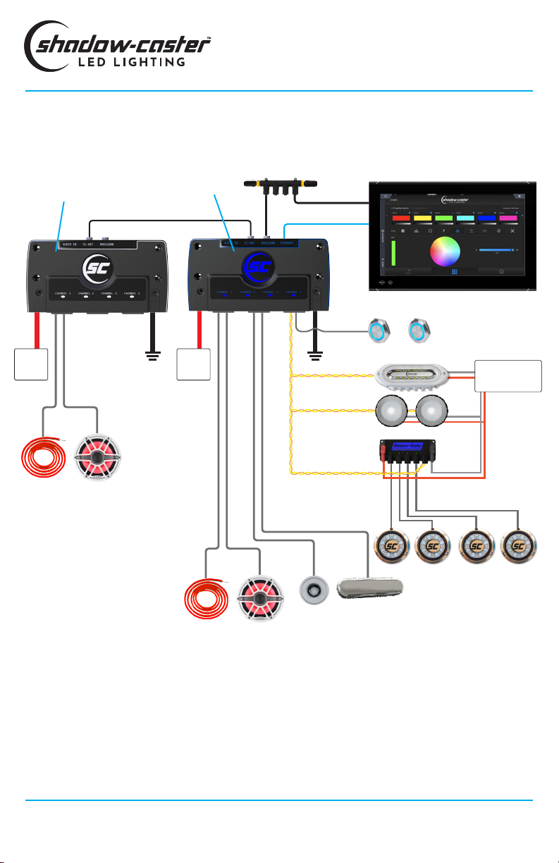
CONNECING TWO LIGHT COMMANDERS TYPICAL WIRING DIAGRAM
Shadow-Caster™ LED Lighting | 2060 Calumet Street. | Clearwater, FL 33765
p: 1+ 727.474.2877 e: info@shadow-caster.com w: shadow-caster.com
6
LIGHT COMMANDER
INSTALLATION & OPERATION MANUAL
NMEA 2000 Backbone
Shadow-Caster proprietary Ethernet user interface
available for all supported MFDs.
SC-NET cable sold separately
10-30V
Power Source
10-30V10-30V
Light Commander Plus
SCM-LC-N2K-PLUS
4 x channels of RGB(W) lighting
(supports up to 15A per channel)
Light Commander
SCM-LC-N2K
Multi-Function Display
Shadow-NET™
SCM-PD4CH
4 x Channels of RGB(W) lighting
(supports up to 15A per channel)
Ethernet
Zone 1 Zone 6
...
7
Designed & Manufactured
in Clearwater, FL
© 2021 Shadow-Caster™ LED Lighting, All Rights Reserved
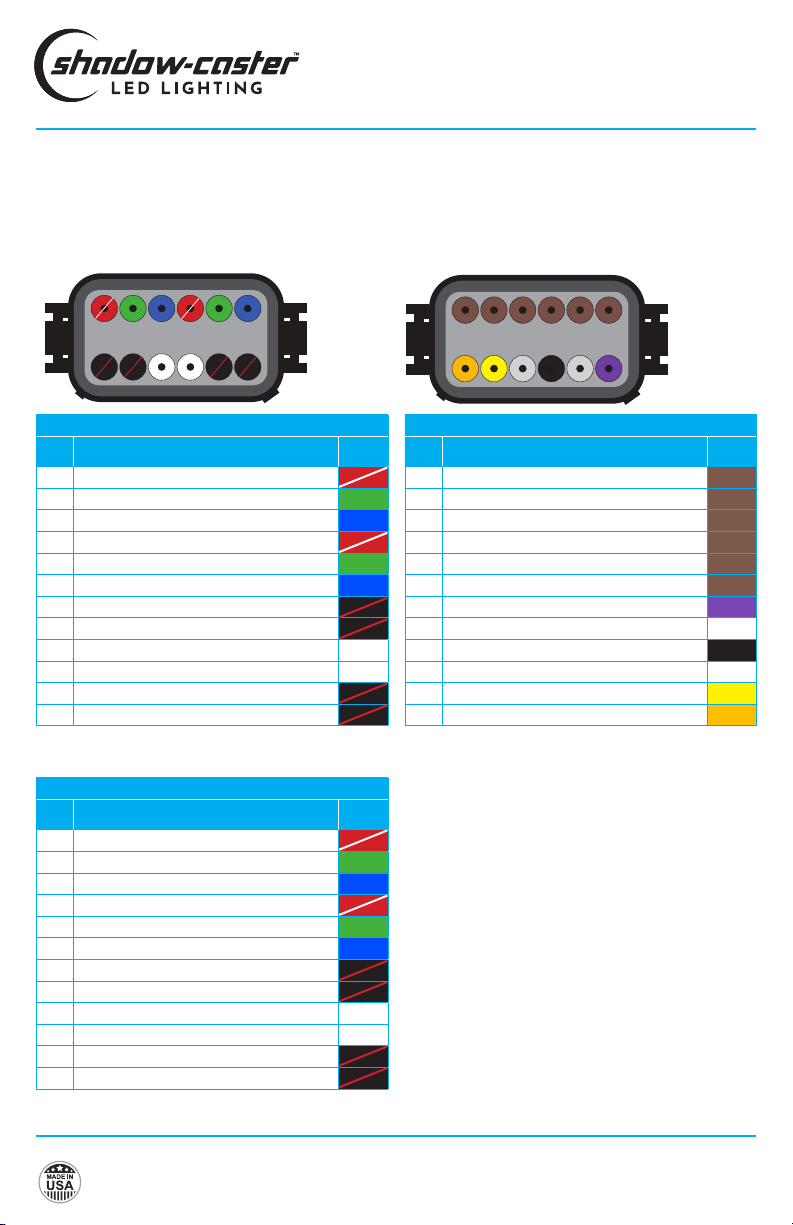
DEUTSCH CONNECTORS FOR LIGHTING AND SWITCH INPUTS
789101112
654321
(BACK VIEW)
CONNECTOR 3
Mating connector - DT06-12SB “B Key”
789101112
654321
(BACK VIEW)
CONNECTOR 1 & 2
Mating connector - DT06-12SA “A Key”
* Combine these two outputs together when current
exceeds 10A.
LIGHT COMMANDER
INSTALLATION & OPERATION MANUAL
* Combine these two outputs together when current
exceeds 10A.
Connector 3 Pin Outs
Pin Description Wire
Color
1+ Input SW Zone 1
2+ Input SW Zone 2
3+ Input SW Zone 3
4+ Input SW Zone 4
5+ Input SW Zone 5
6+ Input SW Zone 6
7+12V Color Control Input
8Not used N/A
9Ground
10 Not used N/A
11 Shadow-NET CAN-H (Yellow)
12 Shadow-NET CAN-L (Orange)
Connector 1 Pin Outs
Pin Description Wire
Color
1Red Channel 1
2Green Channel 1
3Blue Channel 1
4Red Channel 2
5Green Channel 2
6Blue Channel 2
7PWR + OUT Channel 2 (1 of 2)*
8PWR + OUT Channel 2 (2 of 2)*
9White Channel 2
10 White Channel 1
11 PWR + OUT Channel 1 (1 of 2)*
12 PWR + OUT Channel 1 (2 of 2)*
Connector 2 Pin Outs
Pin Description Wire
Color
1Red Channel 3
2Green Channel 3
3Blue Channel 3
4Red Channel 4
5Green Channel 4
6Blue Channel 4
7PWR + OUT Channel 4 (1 of 2)*
8PWR + OUT Channel 4 (2 of 2)*
9White Channel 4
10 White Channel 3
11 PWR + OUT Channel 3 (1 of 2)*
12 PWR + OUT Channel 3 (2 of 2)*
Shadow-Caster™ LED Lighting | 2060 Calumet Street. | Clearwater, FL 33765
p: 1+ 727.474.2877 e: info@shadow-caster.com w: shadow-caster.com
8
INSTALLATION
LIGHT COMMANDER INSTALLATION
Central mounting locations under the helm areas or in
the bilges are acceptable.
1. The Light Commander should be mounted with
Deutsch wire connectors facing down.
2. Use the included four 8 x 3⁄4” SS pan head screws
for mounting.
RECOMMENDED WIRE GAUGES
Scan the QR Code or click here to
view our recommended wire gauge
chart.
LIGHT COMMANDER POWER REQUIREMENTS
See the Shadow-Caster™ wire AWG recommendations
for detailed calculations. It is very important to have
sucient gauge wire feeds for RGB lighting. Typical
installations use 8AWG or larger wire.
It is recommended to separate feeds for lighting and
for sensitive stereo power feeds with direct runs to the
battery or a heavy gauge distribution point.
The Light Commander uses digital current sensing to
detect over current conditions. When this is detected,
the Light Commander will disconnect RGBW channels
from power and ash the backlit logo and channel
lights red to indicate a fault condition.
The Light Commander will work in 12V or 24V systems.
Please note that 12V or 24 compatible RGB(W)
products should be used depending on the application.
SELECTING RGB OR RGBW LIGHTING
The Light Commander is pre-congured for RGB output.
TO CONFIGURE FOR RGBW
1. Press and hold buttons 1 and 2.
2. Apply main power to the controller - the white
channels should immediately start ashing.
3. Once detected, release switch 1 & 2 and cycle power
to resume normal operation.
Note: The minimum detection level is 100mA.
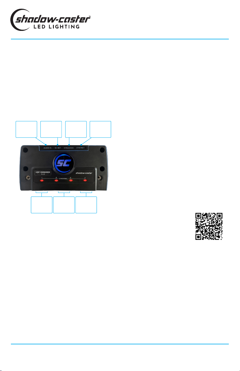
LIGHT COMMANDER CONNECTIONS
The Light Commander has four built in RGBW channels.
By default these RGBW channels correspond to zones
1-4, identied in the device list as "LOCAL 1-4" (see
Congure Devices screen shot on page 11). However,
they are independent and can be assigned to any of the
congured zones 1-6 supported by the controller.
The Light Commander will support 15 amps on each
of the 4 RGB(W) channels, for a total of 60 amps in the
entire Light Commander.
Note: Shadow-NET™ lighting devices communicate
through the orange and yellow Shadow-NET™ interface
on connector 3, and can be assigned to any zone 1-6.
As Shadow-NET™ devices do not draw power through
the controller, they do not contribute to the Light
Commander's total load calculation.
LIGHT COMMANDER
INSTALLATION & OPERATION MANUAL
Shadow-NET™
& Switch
Connections
3.5mm Jack
(Music Sync)
Inputs
Zones 3&4
RGB(W)
Connections
Zones 1&2
RGB(W)
Connections
NMEA 2000
Connection
Shadow-NET™
Compatible
Devices
Ethernet
(SCM-LC-N2K-
PLUS only)
9
Designed & Manufactured
in Clearwater, FL
© 2021 Shadow-Caster™ LED Lighting, All Rights Reserved
SHADOW-NET™ DEVICES
Connect Shadow-NET™ enabled devices to the orange
and yellow Shadow-NET™ wires coming from the Light
Commander.
As soon as the Light Commander receives power,
multiple channels of digital messages start
broadcasting on these wires. These messages allow
Shadow-NET™ enabled devices to be connected
without a switch. Initially these commands are for
attached lights to turn off. As soon as a command is
given to the Light Commander to go to a color, these
attached devices will receive a message to go to the
corresponding color and brightness.
OPTIONAL PARTS
• SCM-ZC-REMOTE Additional Remote Control
• SCM-MFD-BRIDGE MFD Communications Bridge
• SCM-SCNET-01 1meter Cable
• SCM-SCNET-02 2 meter Cable
• SCM-SCNET-04 4 meter Cable
• SCM-SCNET-Y Y Cable
LIGHT COMMANDER
INSTALLATION & OPERATION MANUAL
ADDING ADDITIONAL REMOTES AND
MULTI-FUNCTION DISPLAYS
A SCM-ZC-REMOTE device can be added to the
installation by connecting to the Shadow-NET™ cable.
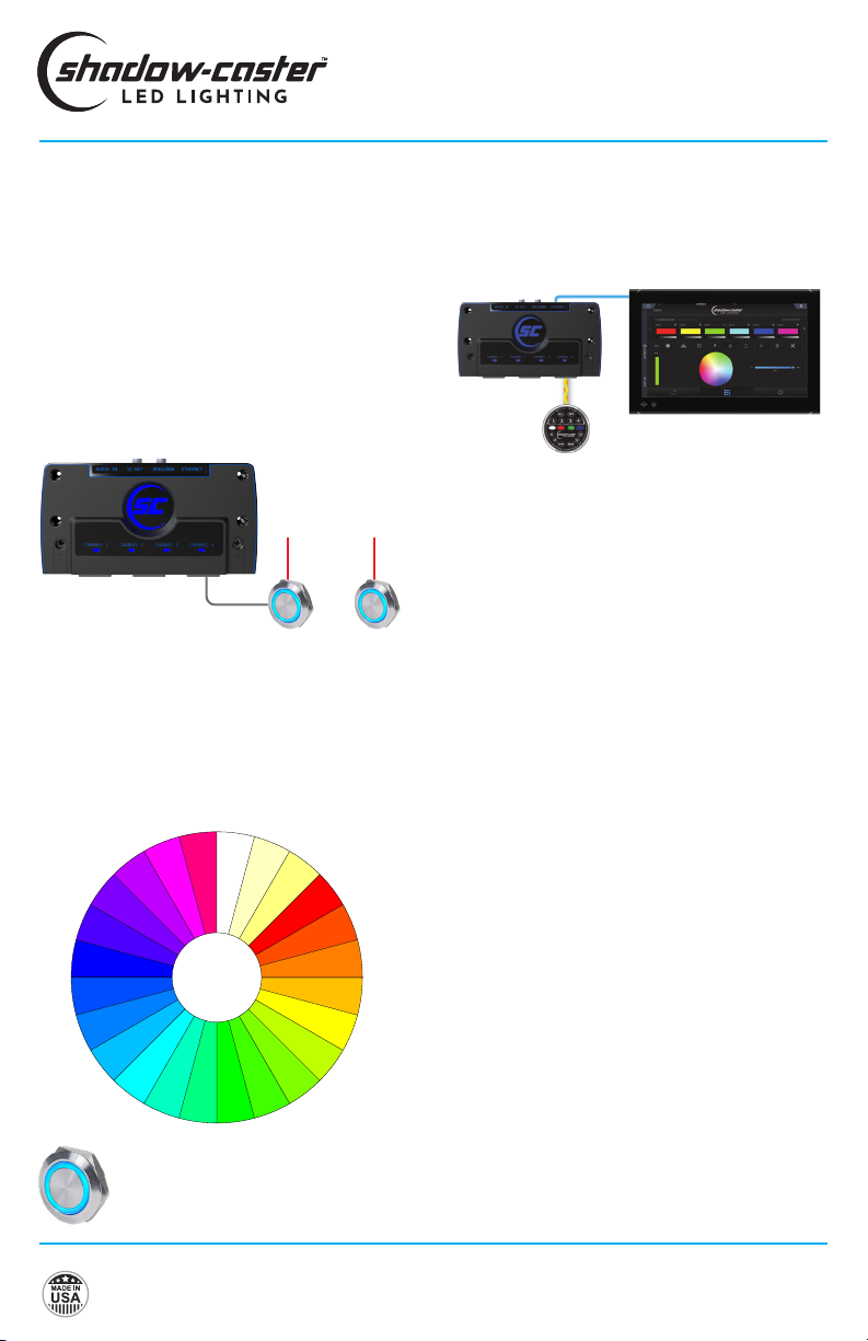
SWITCH INPUTS (OPTIONAL)
The Light Commander supports zone activation
switches. This feature allows a lighting zone to be
easily turned on, off and dimmed without using the
control screen.
There are 6 zone switch inputs located on connector 3.
The inputs are congured for momentary '+' inputs.
The rst button press will turn the corresponding
lighting zone on to white, the second press will turn the
lights off.
Pressing and holding the input will toggle between
dimming and stepping up brightness.
There is one global control input, that will step between
colors on subsequent presses.
Holding the control switch on for more than 1 second
will start color rotation. Color rotation can be stopped
by a subsequent button press.
Press switch to turn zone on/off.
Press and hold switch for dimming. Zone 1 Zone 6
...
+12/24V DC
MFD
SCM-ZC-REMOTE
Shadow-NET
Ethernet
Cool White
Neutral White
Warm White
Red
Yellow
Green
Blue
START
COLOR INDEX CYCLE
•Press to step to next color
•Press and hold to start color rotation
LIGHT COMMANDER
INSTALLATION & OPERATION MANUAL
MUSIC SYNC
The music sync feature samples the music directly
from a 3.5mm stereo analog input. There are several
modes available for syncing to amplitude or frequency
content in the music.
OPTIMIZING MUSIC SYNC
1. Turn music to typical listening volume, and press
PAUSE on your stereo system. This will provide the
lighting controller with an input signal representative
of the audio system background noise.
2. Adjust the sensitivity up until the lights start
blinking/ickering.
3. Play the music and adjust the sensitivity and signal
rate. This adjusts how quickly the lights respond.
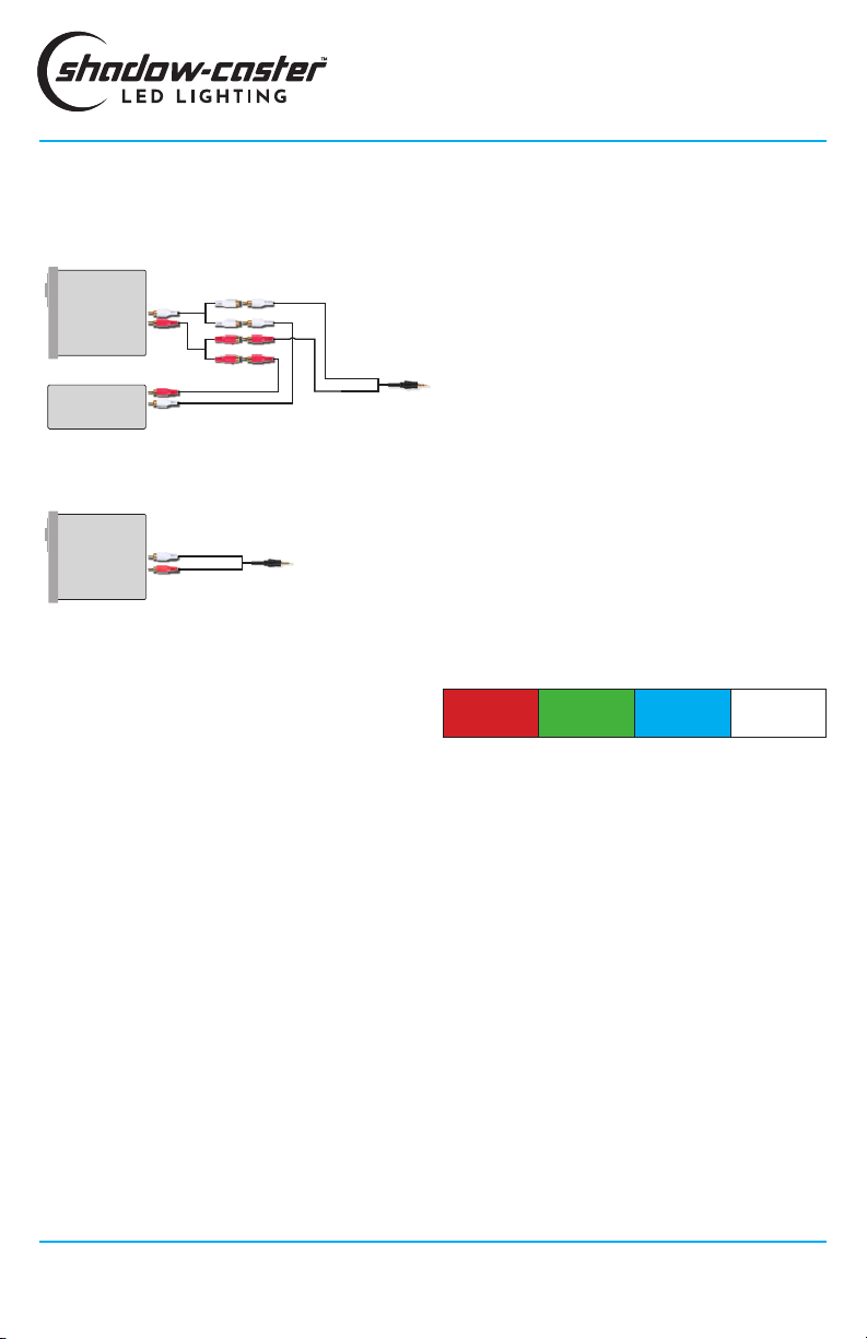
CONNECTING STEREO INPUT FOR
STEREO MUSIC SYNC INPUT
Stereo
Amp To 3.5mm
Female Audio
Jack Input
RCA (Phono)
Cables & Splitters
Connecting a stereo and amplier
Connecting a stereo
Stereo
RCA (Phono) Cables to
3.5mm Female Audio Jack Input
BEST PRACTICES FOR MITIGATING
NOISE ISSUES
Noise interference is common in systems with RGB
lighting controls and amplied stereo systems. The
advanced circuitry in the lighting controller does
everything possible to protect from this.
Utilizing installation best practices will further mitigate
these issues.
1. Make sure to supply ample gauge power and sepa-
rate distribution points from stereo power.
2. Run RGB power wires as far as possible from the
speaker feeds for the stereo. Run separate bundles
where possible.
OPTIMIZING MUSIC SYNC FROM SWITCHES
1. Press and hold buttons 1 and 3 before applying
power to the unit. The unit will blink red and green to
indicate that music adjustment mode is activated.
2. Set music to desired volume, then hit pause on
the music so that only the background signal is
detected.
3. Click button 3 until lights blink and icker. Click
button one to to decrease sensitivity by one step at a
time until lights stop ickering.
4. Press button 5 to store settings. Lights will ash
green to indicate this is good.
FREQUENCY MODE
Frequency mode is the recommended sync mode as it
offers the largest array of color options.
The lighting controller uses a digital signal processor
to extract the relative intensities of low, mid and high
frequency content.
The music mode defaults to an RGB color sequence.
In this case, red corresponds to low frequencies, green
to mid range frequencies, and blue to high frequencies.
If no signal is present or below the threshold, the color
will default to the last color in the sequence or a fourth.
Low
Frequencies
Mid Range
Frequencies
High
Frequencies
Default
Background
Color
Shadow-Caster™ LED Lighting | 2060 Calumet Street. | Clearwater, FL 33765
p: 1+ 727.474.2877 e: info@shadow-caster.com w: shadow-caster.com
10
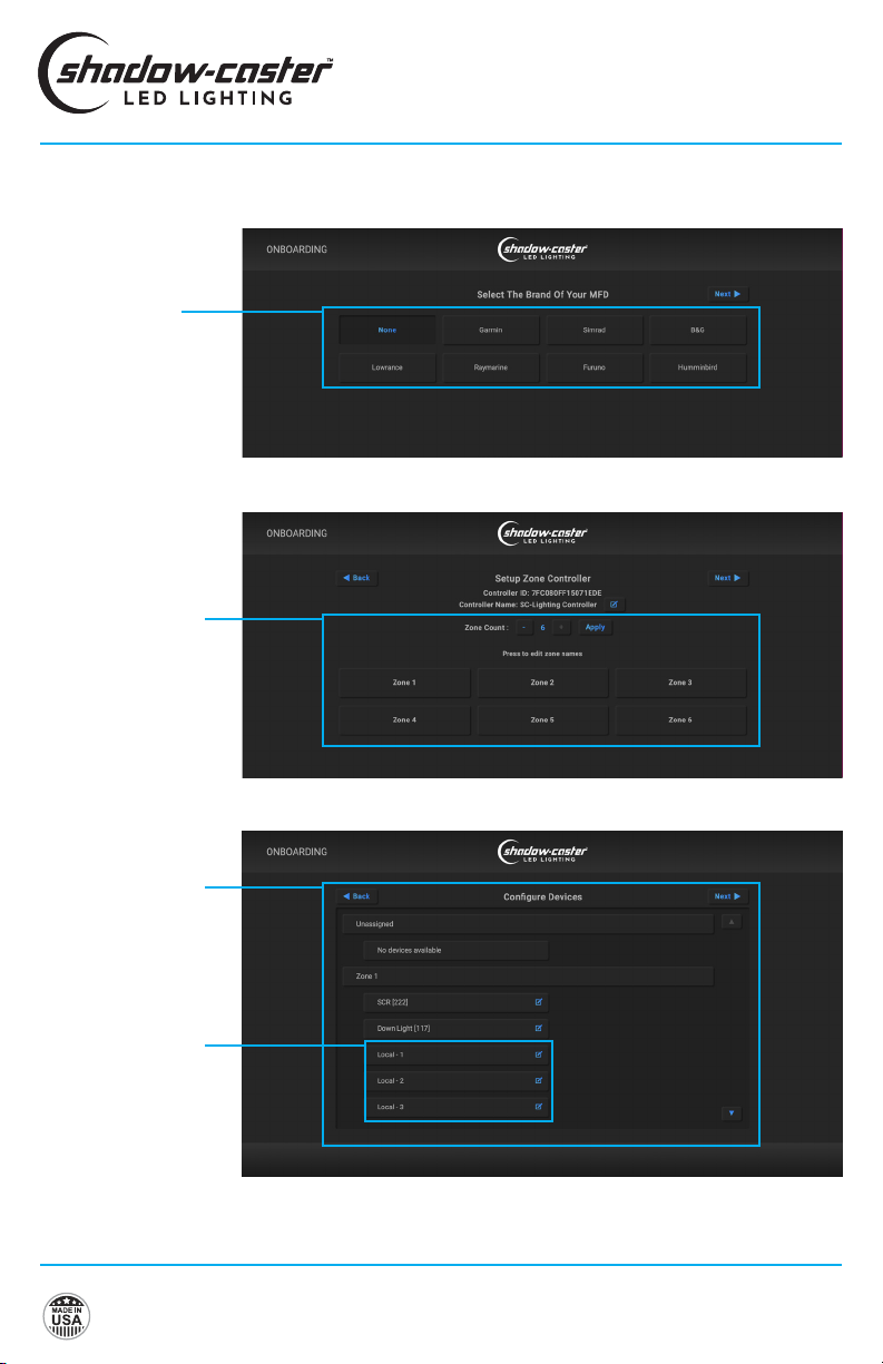
ONBOARDING
BASIC OPERATIONS FOR SHADOW-CASTER MFD USER INTERFACE
LIGHT COMMANDER
INSTALLATION & OPERATION MANUAL
Select the make of
your MFD
Setup Zone Controller
Set the number and
names of required
zones.
Congure Devices
Identify all of the
lighting devices and
then assign them to
the desired zone.
"Local" refers to built in
RGB channels.
11
Designed & Manufactured
in Clearwater, FL
© 2021 Shadow-Caster™ LED Lighting, All Rights Reserved
LIGHT COMMANDER
INSTALLATION & OPERATION MANUAL
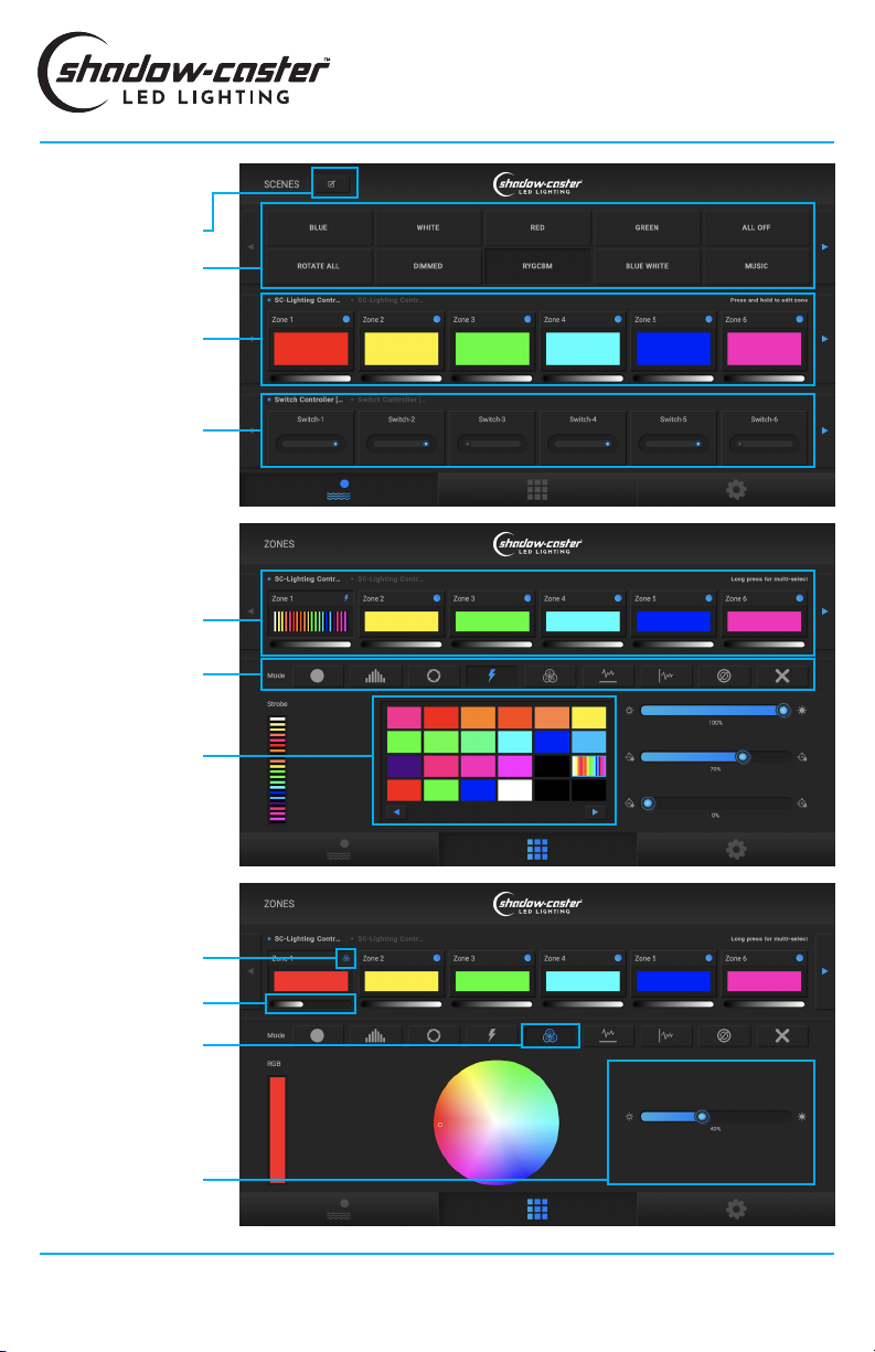
SCENES (DEFAULT
HOME SCREEN)
ZONES
Select lighting scenes
Name and save scenes
View zone status for
the scene
Turn on/off switches
Note: this section only
appears if SCM-PWR6
switch module or other
compatible devices are
connected.
Select zones
Select lighting mode
Select zone color
Select RGB mode
to use color wheel
selector
Zone brightness
indication
Zone mode indication
Edit mode parameters
Shadow-Caster™ LED Lighting | 2060 Calumet Street. | Clearwater, FL 33765
p: 1+ 727.474.2877 e: info@shadow-caster.com w: shadow-caster.com
12
LIGHT COMMANDER
INSTALLATION & OPERATION MANUAL
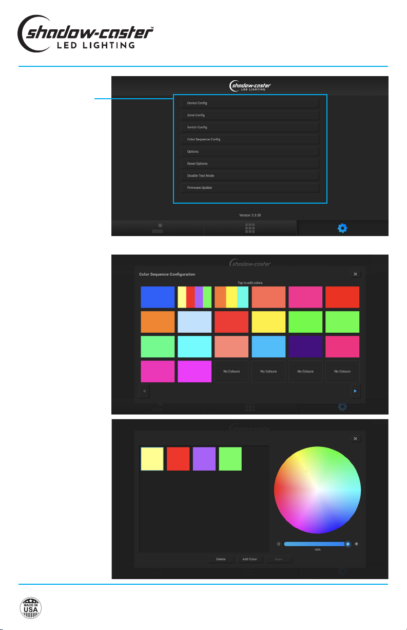
SETTINGS
Edit general settings,
reset and congure
devices and update
rmware.
COLOR SEQUENCE
CONFIGURATION
The Light Commander can
store 60 custom colors or
color sequences.
The rst 30 of these are
reserved for default colors
and built-in sequences.
To add a single color or
custom sequence simply
select the color and hit
"Add Color".
Up to 21 colors can be used
in any given sequence.
13
Designed & Manufactured
in Clearwater, FL
© 2021 Shadow-Caster™ LED Lighting, All Rights Reserved
Shadow-Caster™ LED Lighting | 2060 Calumet Street. | Clearwater, FL 33765
p: 1+ 727.474.2877 e: info@shadow-caster.com w: shadow-caster.com
14
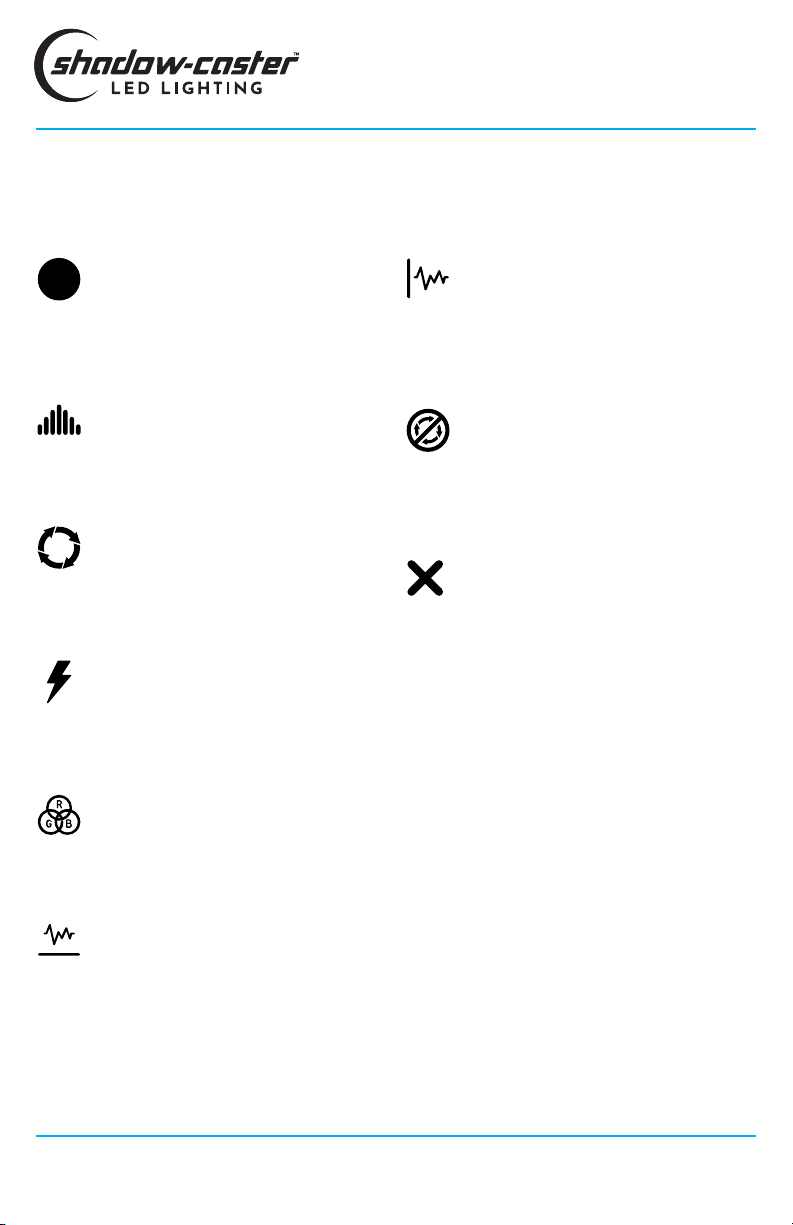
LIGHTING MODES
BASIC OPERATIONS FOR SHADOW-CASTER MFD USER INTERFACE
LIGHT COMMANDER
INSTALLATION & OPERATION MANUAL
SOLID COLOR
Easily recall colors and color sequences. If selecting a
sequence, a rate will be applied to changing these.
COLOR FADE
Rotates colors with the overall brightness going up and
down.
COLOR CHANGE
Transitions between colors and sequences but keeps
overall brightness the same.
FLASH STROBE
Flashes single colors or sequences with changeable
rate.
RGB COLOR WHEEL
Quickly select any color and brightness.
FREQUENCY MUSIC SYNC
Uses full spectrum digital signal processing to go with
the music.
AMPLITUDE MUSIC SYNC
Sets the music to go with the beat of the music. Picks
up on the volume peaks in the music, can use a single
color or rotate through a sequence.
NO CHANGE
If you want to create a scene that does not affect other
lights, Setting a zone to "No change" will leave them
unaffected.
OFF
Simply sets a zone to off.

15
Zone names can be
customized
Zone color indicates
current zone color or
function
Press to slide out
lighting interface
Select between zones
or scene selection
ZONE CONTROL
Customizable
scene menu
SCENE SELECTION
BASIC OPERATIONS FOR SIMRAD NMEA 2000 LIGHTING INTERFACE
LIGHT COMMANDER
INSTALLATION & OPERATION MANUAL
15
Designed & Manufactured
in Clearwater, FL
© 2021 Shadow-Caster™ LED Lighting, All Rights Reserved

BRIGHTNESS
ADJUSTMENT SCREEN
Adjust brightness
Lighting effects
Adjust color and hue
SINGLE COLOR
ADJUSTMENT SCREEN
DYNAMIC LIGHTING
EFFECTS SCREEN
Dynamic function
selection
Color selection
Brightness
LIGHT COMMANDER
INSTALLATION & OPERATION MANUAL
Shadow-Caster™ LED Lighting | 2060 Calumet Street. | Clearwater, FL 33765
p: 1+ 727.474.2877 e: info@shadow-caster.com w: shadow-caster.com
16
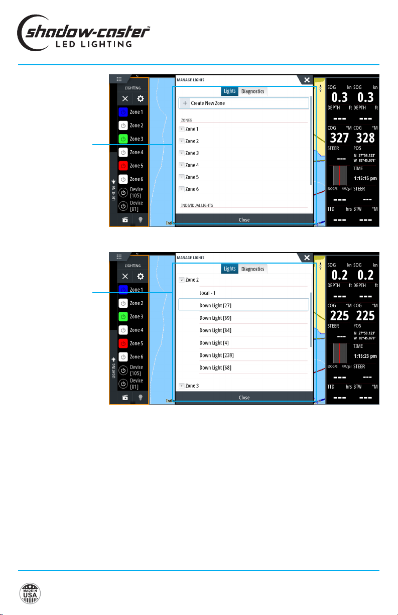
ZONE CONFIGURATION
& LIGHT ASSIGNMENT
SCREENS
Zone conguration
and light assignment
Zone light assignment
LIGHT COMMANDER
INSTALLATION & OPERATION MANUAL
17
Designed & Manufactured
in Clearwater, FL
© 2021 Shadow-Caster™ LED Lighting, All Rights Reserved
SHADOW-NET™ LIGHTS STAY ON
If the connected Shadow-NET™ lights are not turning
off at initial power up then there is a challenge with the
Shadow-NET™ connection.
Check the orange and yellow wire connections are not
reversed and are fully connected.
FACTORY RESET
Press and hold buttons 1 and 7 at start up.
TROUBLESHOOTING
MUSIC SYNC NOT WORKING
Verify that an appropriate 3.5mm stereo jack is being
used and that there is a usable signal.
If a separate output zone is used, verify that the output
is enabled and the output is set to a usable volume.
It is not recommended to use a subwoofer output, as
certain sync modes require the full audio range.
SHADOW-NET™ LIGHTS WILL OCCASIONALLY
LOCK UP AND STOP RECEIVING MESSAGES
This indicates that there is a noise issue on the
Shadow-NET™ communication lines. Typically this is
caused by insucient gauge wire feeding one or more
Shadow-NET™ connected lights.
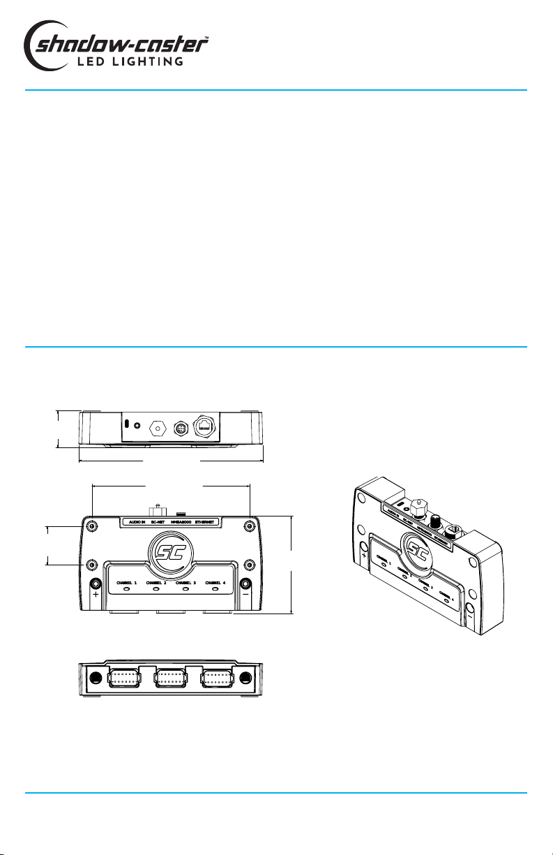
DIMENSIONS
1.79"
[45.4mm]
8.9" [226mm]
7.63" [193.7mm]
MOUNTING
4.711"
[119.7mm]
1.88" [47.6mm]
MOUNTING
LIGHT COMMANDER
INSTALLATION & OPERATION MANUAL
Shadow-Caster™ LED Lighting | 2060 Calumet Street. | Clearwater, FL 33765
p: 1+ 727.474.2877 e: info@shadow-caster.com w: shadow-caster.com
18

Shadow-Caster™ LED Lighting |2060 Calumet Street. |Clearwater, FL 33765
p: 1+ 727.474.2877 e: info@shadow-caster.com w: shadow-caster.com
Designed & Manufactured
in Clearwater, FL
© 2021 Shadow-Caster™ LED Lighting, All Rights Reserved
JUN23
Other manuals for SCM-LC-N2K
1
This manual suits for next models
1
Table of contents
Other Shadow-Caster Lighting Equipment manuals


Popular Lighting Equipment manuals by other brands


Access Lighting
Access Lighting 20291LEDDLP quick start guide

Milwaukee
Milwaukee REDLITHIUM USB ROVER 2114-21 instruction manual

American DJ
American DJ DJ SCAN User instructions

Lightolier
Lightolier SS 1 LAMP specification

Larson Electronics
Larson Electronics EPL-MPM-150LED Instruction guide

PROLED
PROLED L6OP7 Series installation manual


