SOLARMG SG-OST50-60T User manual
REV.0 – Preliminary S.MG-MU:SG-OST50-60T
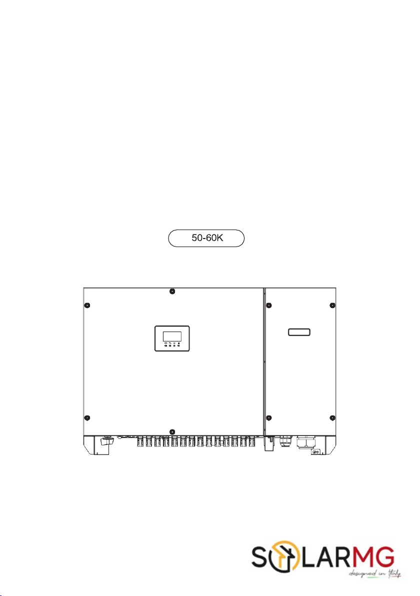
User Manual

REV.0 – Preliminary S.MG-MU:SG-OST50-60T
Contents
Forward-
-
01
Application Model ______________________________________________________________ 01
lntended Audience _____________________________________________________________ 01
Symbol Conventions ____________________________________________________________ 02
1
Safety
Precautions
-
03
1.1
Personnel Safety ___________________________________________________________ 03
1.2
The PV lnverter Protection ___________________________________________________ 03
1.3
lnstallation Safety ___________________________________________________________ 03
1.4
Electrical Connections _______________________________________________________ 04
1.5
Operating and Commissioning ________________________________________________ 04
1.6
Maintenance _______________________________________________________________ 04
1.7
Additional lnformation ________________________________________________________ 05
2
Overview of the lnverter -
-
06
2.1
Functional Models __________________________________________________________ 06
2.1.1 Function ______________________________________________________________ 06
2.1.2 Model Description ______________________________________________________ 06
2.2
Network Application _________________________________________________________ 06
2.2.1 Grid-tied PV Power Systems ____________________________________________ 06
2.3
Outline and Dimensions ______________________________________________________ 07
2.3.1 Outline _______________________________________________________________ 07
2.3.2 Dimensions ___________________________________________________________ 08
2.4
Working Modes ____________________________________________________________ 09
3
Storage
-10
4
lnstallation - 11
4.1
Checking the Outer Packing __________________________________________________ 11
4.2
Moving the 50K/ 60K _______________________________________________________ 12
4.3
ldentify the PV lnverter ______________________________________________________ 12
4.3.1
Nameplate
___________________________________________________________
12
4.3.2 Compliance and Safety Symbols _________________________________________ 13
4.4
lnstallation Requirements _____________________________________________________ 13

REV.0 – Preliminary S.MG-MU:SG-OST50-60T
4.4.1 Determining the lnstallation Position ______________________________________ 13
4.4.2 lnstallation Mode Requirements __________________________________________ 16
4.5 Support-mounting the lnverter
________________________________________________
16
4.6
lnstallation Self-check _______________________________________________________ 17
5
Electrical Connections
-18
5.1
Connecting Protection Ground (PGND) Cables __________________________________ 18
5.1.1
Preparation
__________________________________________________________
18
5.1.2 Wiring Procedures _____________________________________________________ 19
5.2
Connecting AC Output Cables - 20
5.2.1 Preparation - - 20
5.2.2 Procedure of Connecting AC Cables - 21
5.3
Connecting the PV Strings
- - 22
5.3.1 Preparation - - 23
5.4
Connecting Communications Cables - 26
5.4.1 Communications Mode Description - 26
5.4.2 Connecting RS485 Communications Cables - 28
5.4.3 Setting RS485 Communications Address - 30
5.5
lnstallation Verification - 31
6
System Operation -
6.1
Powering ON the lnverter
6.2
Powering OFF the lnverter
-32
- 32
- 32
7
User lnterface
-33
8 Maintenance
-
-37
8.1
Routine Maintenance - 37
8.2
The lnverter Troubleshooting - 38
8.3
Removing the lnverter - - 40
9
Quality
Guarantee
-42
9.1
Quality Terms
- - 42
9.2
Liability Waiver
- - 42
10 Disposal of the lnverter
-
-43

REV.0 – Preliminary S.MG-MU:SG-OST50-60T
11 Technical Specifications
12 Technical Assistance
-46
49

REV.0 – Preliminary S.MG-MU:SG-OST50-60T
Introduction
Dear User,
This user manual introduces the inverter in terms of its installation, electrical connections,
operation, commissioning, maintenance, and troubleshooting. Please read through the manual
carefully before installing and using the inverter, and keep the manual well for future reference.
Application Model
Grid-tied PV string inverter
• 50K
• 60K
lntended Audience
This user manual is intended for photovoltaic (PV) inverter operating personnel and qualified
electrical technicians.
2
REV.0 – Preliminary S.MG-MU:SG-OST50-60T
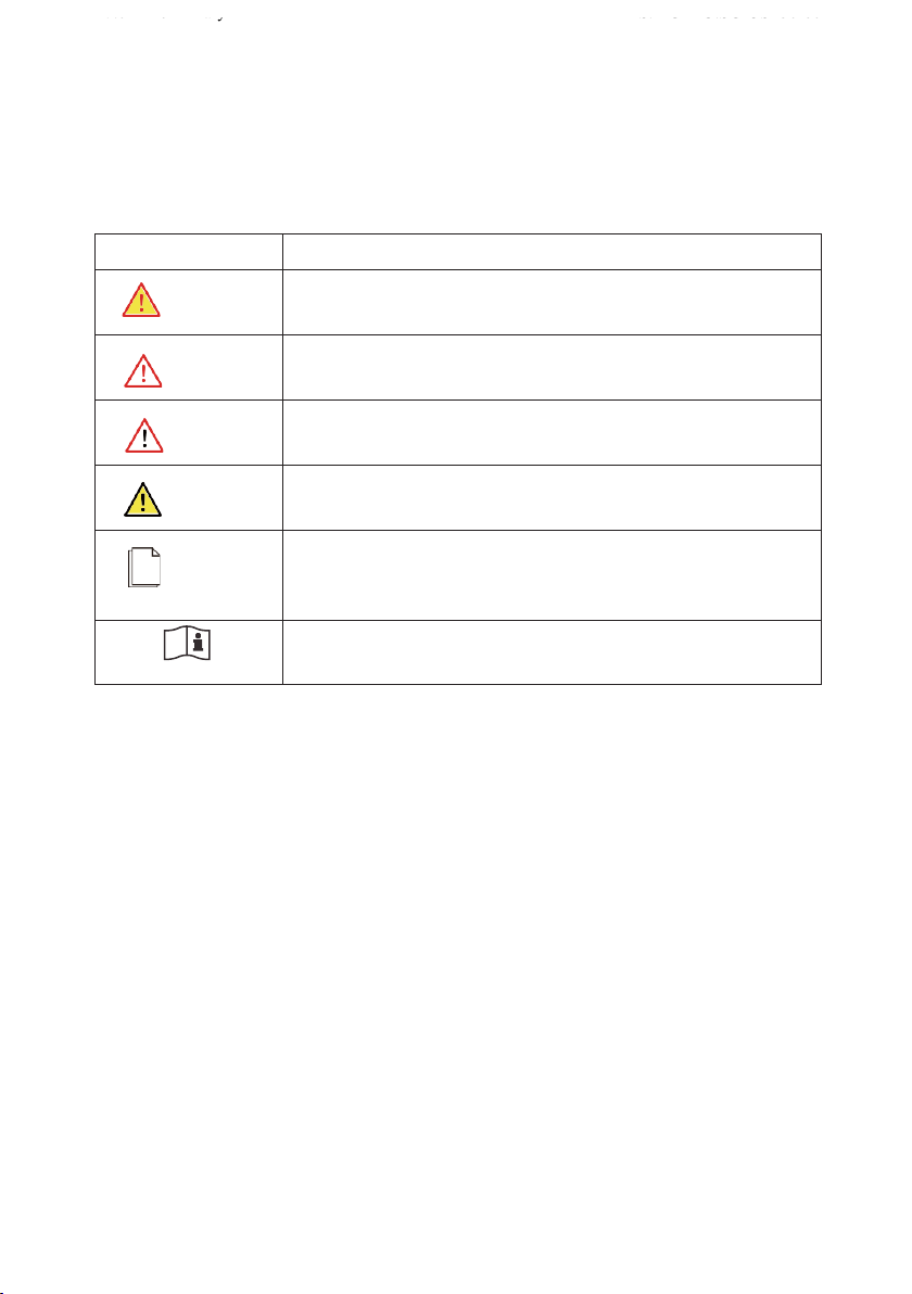
Symbol Conventions
Safety symbols used in this manual, which highlight potential safety risks and important safety
information, are listed as follows:
Symbol
Description
DANGER
lndicates an imminently hazardous situation which, if not correctly
followed, will result in serious injury or death.
WARNING
lndicates a potentially hazardous situation which, if not correctly
followed, could result in serious injury or death.
CAUTION
lndicates a potentially hazardous situation which, if not correctly
followed, could result in moderate or minor injury.
NOTICE
lndicates a potentially hazardous situation which, if not correctly
followed, could result in equipment failure to run, or property damage.
NOTE
Calls attention to important information, best practices and tips:
supplement additional safety instructions for your better use of the
PV inverter to reduce the waste of your resource.
Refer to documentation (Remind operators to refer to the
documentation shipped with the inverter).

3
REV.0 – Preliminary S.MG-MU:SG-OST50-60T
1
Safety Precautions
Please read these safety precautions in User Manual carefully.
1.1 Personnel Safety
a. The PV inverter must be installed, electronically connected, operated and maintained through
specially trained technician;
b. The qualified technician must be familiar with the safety regulations of electrical system,
working process of PV power generation system, and standards of local power grid;
c. The technician must read through this User Manual carefully and master il before any operation.
1.2 The PV lnverter Protection
.
a.
Do not tamper with any warning signs on the inverter enclosure because these signs contain
important information about safe operation.
b.
Do not remove or damage the nameplate on the inverter's enclosure because il contains
important product information.
c.
Do not remove the anti-dismantle label on the inverter's enclosure because il is the basis for
product warranty.
1.3 lnstallation Safety
a. Ensure there is no electronical connections around ports of the PV inverter before installing;
b. Adequate ventilation must be provided for inverter installation location. Mount the inverter in
vertical direction, and ensure that no object is put on the heat sink affecting the cooling. (For
details, refer to Chapter 4 lnstallation)
Please read the User Manual carefully before installing the PV inverter;
warranty or liability will be void if damage is caused by installation
faults.

4
REV.0 – Preliminary S.MG-MU:SG-OST50-60T
1.4 Electrical Connections
a. Input terminals of the PV inverter apply only to input terminals of PV String; do not connect
any other DC source to the input terminals.
b. Before connecting PV modules, ensure that is its voltage is within the safe range; when
exposed to any sunlight, PV modules can generate high voltage.
c. AII electrical connections must meet the electrical standards of the country or region.
d. Cables used in electrical connections must be well fixed, good insulation, and with
appropriate specification.
1.5 Operating and Commissioning
a. Before getting the permission of electrical power sector in the country/ region, the grid-tied
PV inverter cannot start generate power.
b. Follow the procedures of commissioning described in the user manual when commissioning
the PV inverter.
c. Do not touch any other parts ‘surface except the DC switch when the PV inverter is operating;
its partial parts will be extremely hot and can cause burns.
1.6 Maintenance
Before installing the inverter, check all electrical ports to ensure no
damage and no short circuit. Otherwise personal casualty and/or fire
will occur.
,
DANGER
While the inverter operating, high voltage can lead to an electrical
shock hazard, and even cause personal casualties. Therefore,
operate the PV inverter strictly according to the safety precautions in
the user manual.
DANGER
Power OFF all electrical terminals before the inverter maintenance;
strictly comply with the safety precautions in this document when
operating the inverter.
,
DANGER

5
REV.0 – Preliminary S.MG-MU:SG-OST50-60T
a.
For personal safety, maintenance personnel must wear appropriate personal protective
equipment (like insulation gloves and protective shoes) for the inverter maintenance.
b.
Place temporary warning signs or erect fences to prevent unauthorized access to the
maintenance site.
c.
Follow the procedures of maintenance stipulated in the manual strictly.
d.
Check the relevant safety and performance of the inverter; rectify any faults that may
compromise the inverter security performance before restarting the inverter.
1.7 Additional lnformation
To avoid any other unforeseeable risk, contact us immediately, if there
is any issue found during operation.
NOTICE
6
REV.0 – Preliminary S.MG-MU:SG-OST50-60T
2
Overview of the lnverter
This chapter introduces the inverter and describes its functional model, network application,
appearance, dimensions, and working process etc.
2.1 Functional Models
2.1.1 Function
This series is a three-phase grid-tied PV string inverter (transformer less) that converts the DC
power generated by PV strings into AC power and feeds the power into power grid.
WARNING
The inverter is transformerless. Add an isolation transformer before
grounding the positive/ negative terminal of PV modules (like Thin
Film module) for operation.
WARNING
Do not connect PV modules in parallel lo several PV inverters for
operation.
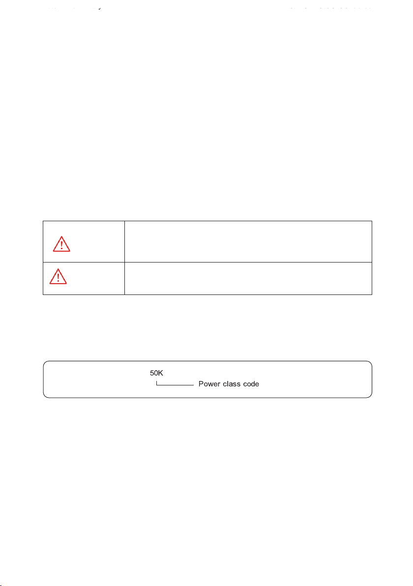
2.1.2 Model Description
Figure 2.1 shows a model number of the inverter, using 50K as an example.
Figure 2.1 Model number descriptions
2.2 Network Application
2.2.1 Grid-tied PV Power Systems
This series applies to grid-tied PV power systems for industrial / commercial rooftops,
fishing / farmers light complementary power generation systems, and large ground-based power
stations. Typically, these series inverters are used in low-voltage grid-tied PV power system,
as shown in Figures 2.2&2.3

7
REV.0 – Preliminary S.MG-MU:SG-OST50-60T
Figure 2.2 a low-voltage grid-tied PV power system
Figure 2.3 Power grids supported by these series inverters
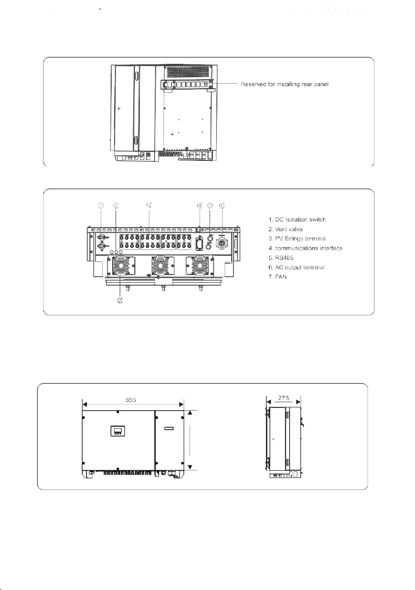
2.3 Outline and Dimensions
2.3.1 Outline
Figures 2.4 to 2.6 show the outline of the inverters as follows:
Figure 2.4 The front view and amplification effect of LED indicator, area
8
REV.0 – Preliminary S.MG-MU:SG-OST50-60T
Figure 2.5 The rear view of this series inverter
Figure 2.6 The bottom view of this series inverter
2.3.2 Dimensions
Figures 2.7 shows the dimensions of these series inverters as follows:
Figures 2.7 The dimensions of this series (unit: mm)
555

9
REV.0 – Preliminary S.MG-MU:SG-OST50-60T
2.4 Working Modes
Three working modes of the inverter are shown as follows: standby, operating, and shutdown.
Table 2.1 shows the conditions for the inverter lo switch between working modes.
Modes
Description
Standby
The PV inverter enters the standby mode when
>the input voltage of PV Strings can enable auxiliary power supply lo run,
but cannot meet the inverter operation requirements.
>the input voltage of PV Strings can meet the inverter lo-start requirements,
but cannot meet its minimum power requirements.
Operating
When the PV inverter is grid-tied and generates electricity, it:
> tracks the maximum power point to maximize the PV String output.
> converts DC power from PV strings into AC power and feeds the power
to the power grid.
The PV inverter will enter to the shutdown mode if detecting a fault or a
shutdown command.
Shutdown
The PV inverter switches from standby or operating mode lo shutdown
mode if detecting a fault or a shutdown command.
The inverter switches from shutdown mode to standby mode if receiving
a Startup command or detecting that a fault is rectified.
Table 2.1 Working modes description

10
REV.0 – Preliminary S.MG-MU:SG-OST50-60T
3
Storage
This chapter describes the storage requirements for the inverter.
The following storage instructions apply if the PV inverter will not be deployed immediately:
> Do not unpack the inverter (put desiccant in the original box if the PV inverter is unpacked).
>
Store the PV inverter at a temperature range of -40°C lo +70°Cand with the relative humidity
of 0% lo 100% (no condensing).
> The PV inverter should be stored in a clean and dry place and be protected from dust and
water vapor corrosion.
> A maximum of six layers of inverters can be stacked.
> Do not position the inverter al a front tilt, excessive back tilt, or side tilt, or upside down.
>
Conduct periodic inspection during storage. Replace the packing materials immediately if any
rodent bites are found.
>
Ensure that qualified personnel inspect and test the inverter before use if il has been stored
fora long time.
11
REV.0 – Preliminary S.MG-MU:SG-OST50-60T
4
lnstallation
DANGER
Do not install the inverter on flammable building materials or in an
area that stores flammable or explosive materials.
CAUTION
Do not install the inverter in a place where personnel are likely to
come into contact with its enclosure and heat sinks to avoid electrical
shock / burn.
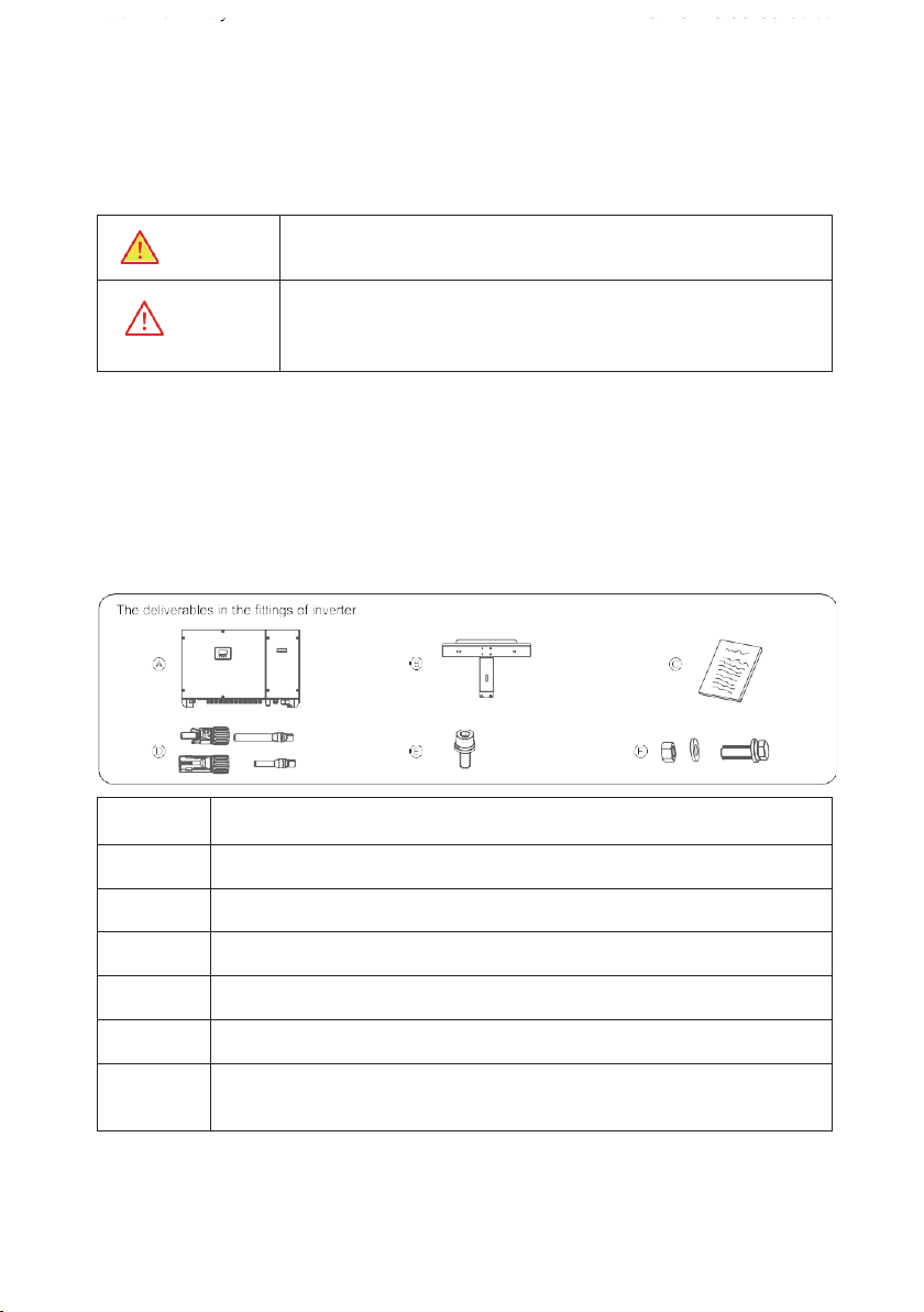
4.1 Checking the Outer Packing
a. When receiving the inverter, check that the packing materials are intact.
b. After unpacking, check that the deliverables are complete, intact, and consistent with your
order list.
c. Examine the PV inverter and its fittings for damage such as scraps and cracks.
ltems
Deliverables
A
The
inverter
B
Rear
panel
e
File
package
D
DC
terminal
connector
group
50K(10'2)/60K(12'2)
E
M6
screw
F
Bolt group (including screw, nut)'3
(reserved lor tightening the
support and rear panel)
Figures 4.1 The deliverables: The inverter and its fittings

12
REV.0 – Preliminary S.MG-MU:SG-OST50-60T
NOTICE
lf any damage mentioned above is found, contact the dealer
immediately.
4.2
Moving the SOK / 60K
After checking the outer packing, move the PV inverter to the designated installation position
horizontally. Hold the handles on both sides of the inverter, as shown in Figure 4.2.
Figure 4.2 Moving the inverter
CAUTION
The inverter is relatively heavy! To prevent device damage and personal
injury, arrange two people to move the inverter and handle with care.
CAUTION
>Do not place the PV inverter with its wiring terminals contacting the
floor because the power ports and signal ports at the bottom of the
device are not designed to support the weight of the inverter.
>When placing the inverter on the floor horizontally, put foam or
paper under to protect its enclosure.
4.3 ldentify the PV lnverter
4.3.1 Nameplate
After moving the PV inverter from packing box, identify it by reading its nameplate labeled on
the side of the inverter. The nameplate contains important product information: the model
information, communications/ technical specifications, and compliance symbols.
13
REV.0 – Preliminary S.MG-MU:SG-OST50-60T
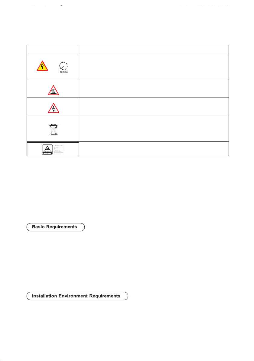
4.3.2 Compliance and Safety Symbols
.
4.4 lnstallation Requirements
According to installation position, two kinds of physical installation are described below in
detail: Support-mounting & wall-mounting.
4.4.1 Determining the lnstallation Position
a.
The inverter is protected lo IP65 and can be installed indoors or outdoors.
b.
The installation method and position must be appropriate for the weight and dimensions of
the inverter.
c.
Do not install the inverter in a place where personnel are likely to come into contact with its
enclosure and heat sinks because these parts are extremely hot during operation.
d.
Do not install the inverter in an area that stores flammable or explosive materials.
a.
The ambient temperature must be below 50°C which ensures the inverter's optimal
operation and extends its service life.
Safety symbol
Description
Electrical shock!
There are residual voltages in the PV inverter. It needs 10 minutes
lo finish discharge.
The PV inverter must not be touched when in operation. lts
enclosure and heat sinks are extremely hot.
Electrical shock! This part is charged. Only qualified and / or trained
electrical technicians are allowed to perform operations on the inverter
lf the inverter service life has expired, dispose it in accordance with
local rules for disposal of electrical equipment waste. Do not dispose
the PV inverter with household garbage.
The PV inverter is compliant with TUV.

14
REV.0 – Preliminary S.MG-MU:SG-OST50-60T
b.
The inverter must be installed in a well ventilated environment to ensure good heat dissipation.
c.
The inverter must be free from direct exposure to sunlight, rain, and snow to extend its service
life. lt is recommended that the inverter be installed in a sheltered place. lf no shelter is
available, build an awning, as shown in Figure 4.3.
Figure 4.3 lnstallation environment with awning (unit: mm)
a. The carrier where the inverter is installed must be fire-proof. Do not install the inverter on
flammable building materials.
b. The wall must be solid enough to bear the weight of the inverter.
c. Do not install the inverter on a wall made of gypsum boards or similar materials with weak
sound insulation to avoid noise disturbance in a residential area.
a.
lt is recommended that the inverter be installed at eye level to facilitate operation and
maintenance.
b.
Reserve enough clearance around the inverter to ensure sufficient space for installation
and heat dissipation, as shown in Figure 4.4.

15
REV.0 – Preliminary S.MG-MU:SG-OST50-60T
Figure 4.4 lnstallation Space Requirements (unit: mm)
c.
c. When installing multiple inverters, install them along the same line (as shown in Figure
4.5) if sufficient space is available, and install them in triangle mode or in stacked mode
(as shown in Figure 4.6) if no sufficient space is available. The installation modes ensure
sufficient space for installation and heat dissipation.
Figure 4.5 lnstallation along the same line (unit: mm)
Figure 4.6 lnstallation in stacked mode
NOTICE
The clearance between multiple inverters must be increased to
ensure proper heat dissipation when they are installed in a hot area.

16
REV.0 – Preliminary S.MG-MU:SG-OST50-60T
4.4.2 lnstallation Mode Requirements
lnstall the inverter upright or at a maximum back tilt of 15 degrees to facilitate heat dissipation.
Below are some correct
I
wrong installation modes, as shown in Figures 4.7&4.8.
Figures 4.7 The correct installation mode
Figure 4.8 The wrong installation modes
NOTICE
The wrong installation will lead to failure of the inverter operation.
4.5 Support-mounting the lnverter
Step 1 Move out the rear panel from the packing case, and determine the positions for the
inverter and the support, shown as in Figure 4.9.
Figure 4.9 The rear panel (unit: mm)
Table of contents
Other SOLARMG Inverter manuals


Popular Inverter manuals by other brands

Rossum
Rossum Control Forge Operation manual

SMA
SMA Sunny Island 4500 Installation & operating instructions

EWM
EWM STICK 350 PWS operating instructions

Analytic Systems
Analytic Systems IPSi305MW Installation & operation manual

Generac Power Systems
Generac Power Systems QT022 Specifications

Generac Power Systems
Generac Power Systems Guardian 5410 Repair manual


