SOLARMG SG-25KWHBT User manual

SOLARMG
HYBRID INVERTER
SG-25/30/36/40/50KWHB
User Manual
REV.1 – Preliminary
S.MG-UM:SG 25-50KWHBT

CONTENTS
REV.1 – Preliminary
S.MG-UM:SG 25-50KWHBT

CONTENTS
1.1 How To Use This Manual………………………………………………………… 5
1.2 Target Groups …………………………………………………………………… 5
1.3 Symbols …………………………………………………………………………… 5
2.1 Safety Notes ……………………………………………………………………… 7
2.2 Statement ………………………………………………………………………… 7
3.1 System Introduction …………………………………………………………… 9
3.2 Product Introduction ………………………………………………………… 10
……………………………………………………… 12
3.4 Operation Modes ……………………………………………………………… 13
……………………………………………… 18
3.6 Unpacking and Storage ……………………………………………………… 19
4.1 Location ………………………………………………………………………… 21
………………………………………………………… 23
5.1 Electrical Wiring Diagram ……………………………………………………
5.2 AC Connection ………………………………………………………………… 30
5.3 Monitoring Device Installation ……………………………………………… 34
5.4 Meter and CT Connection …………………………………………………… 35
5.5 Communication Connection ………………………………………………… 36
5.6 PV String Connection ………………………………………………………… 50
…………………………………… 55
6.1 App Preparation ………………………………………………………………
6.2 Inspection Before Commissioning…………………………………………… 58
6.3 Commissioning Procedure …………………………………………………… 58
……………………………………………………………… 59
7.1 Main Window……………………………………………………………………
7.2 General Setting ………………………………………………………………… 61
2 Safety Instructions ……………………………………… 7
1 About This Manual ……………………………………… 5
3 Product Description……………………………………… 9
4 Installation ………………………………………………… 21
5 Electrical Connection …………………………………… 26
6 Commissioning …………………………………………… 58
7 Screen Operation ………………………………………… 60
REV.1 – Preliminary
S.MG-UM:SG 25-50KWHBT

4
User Manual
SG-25~50KWHBT series
7.3 Advanced Setting …………………………………………………………… 63
……………………………………… 66
7.5 Auto-Test ……………………………………………………………………… 66
7.6 Reactive Power ………………………………………………………………… 68
8.1 Monitoring Device …………………………………………………………… 71
8.2 Cloud monitoring App………………………………………………………… 72
……………………………………………………… 72
9.1 Error Message ………………………………………………………………… 73
………………………………………………………… 78
………………………………………………………… 79
10.1 Technical Parameters………………………………………………………… 80
10.2 Contact Information ………………………………………………………… 89
CONTENTS
8 Monitoring ………………………………………………… 71
9 Troubleshooting ………………………………………… 73
10 Appendix ……………………………………………… 80
REV.1 – Preliminary
S.MG-UM:SG 25-50KWHBT

5
User Manual
SG-25~50KWHBT series
About This Manual
SOLARMG SG-2550KWHBT
products.
SOLARMG
not constitute any express or implied guarantee.
1
7.3 Advanced Setting …………………………………………………………… 63
……………………………………… 66
7.5 Auto-Test ……………………………………………………………………… 66
7.6 Reactive Power ………………………………………………………………… 68
8.1 Monitoring Device …………………………………………………………… 71
8.2 Cloud monitoring App………………………………………………………… 72
……………………………………………………… 72
9.1 Error Message ………………………………………………………………… 73
………………………………………………………… 78
………………………………………………………… 79
10.1 Technical Parameters………………………………………………………… 80
10.2 Contact Information ………………………………………………………… 89
※
-
This manual is applicable to electrical installers with professional qualifications and
①
with hazards.
②Knowledge of the manual and other related documents.
③Knowledge of the local regulations and directives.
Indicates a hazard with a high level of risk that, if not avoided, will result
in death or serious inju.
DANGER
Indicates a hazard with a medium level of risk that, if not avoided, could
result in death or serious inju.
WARNING
※ 1.1 How To Use This Manual
latest manual can be found at www.solarmg.it.
※ 1.2 Target Groups
※ 1.3 Symbols
REV.1 – Preliminary
S.MG-UM:SG 25-50KWHBT

6
User Manual
SG-25~50KWHBT series
Indicates a hazard with a low level of risk that, if not avoided, could
result in minor or moderate inju.
CAUTION
Indicates a situation that, if not avoided, could result in equipment or
propey damage, data loss, equipment peormance degradation.
NOTICE
Indicates additional information, emphasized contents or tips that may
be helpful, e.g., to help you solve problems or save time.
NOTE
REV.1 – Preliminary
S.MG-UM:SG 25-50KWHBT

7
User Manual
SG-25~50KWHBT series
Safety Instructions
2
①
manual strictly.
②Installers need to undergo professional training or obtain electrical related professional
③
the warranty.
④All electrical installations must conform to local electrical safety standards.
⑤
system installation and maintenance.
⑥
authority.
⑦
⑧
⑨
①
②
③Damages caused by installation and use of equipment by non-professionals or un-
trained personnel.
④Damages caused by failure to comply with the instructions and safety warnings in this
document.
⑤Damages of running in an environment that does not meet the requirements stated in
this document.
⑥
※2.1 Safety Notes
※ 2.2 Statement
SOLARMG
REV.1 – Preliminary
S.MG-UM:SG 25-50KWHBT

8
User Manual
SG-25~50KWHBT series
⑦
software codes.
⑧
⑨Any damages caused by the process of installation and operation which don't follow the
local standards and regulations.
⑩Products beyond the warranty period.
REV.1 – Preliminary
S.MG-UM:SG 25-50KWHBT

9
User Manual
SG-25~50KWHBT series
※
-
Product Description
3
Figure 3-1 Schematic diagram of hybrid system
The system is not suitable for supplying life-sustaining medical devices.
It cannot guarantee backup power in all circumstances.
NOTICE
SOLARMG SG-25~50KWHBT
PV
MODULES
BATTERY
HYBRID
INVERTER
LOAD
CURRENT
TRANSFORMER
002456
UTILITYMETER
FORBILLING
PURPOSES
UTILITY
GRID
SMART
METER
ON-GRID
LOAD
Figure 3-2 Applicable grid types
TN-S
SG-25~50KWHBT
Tranformer
TN-C
SG-25~50KWHBT
Tranformer
TN-C-S
SG-25~50KWHBT
Tranformer
TT
SG-25~50KWHBT
Tranformer
SMART
METER
※ 3.1 System Introduction
BACK-UP
REV.1 – Preliminary
S.MG-UM:SG 25-50KWHBT
10
User Manual
SG-25~50KWHBT series
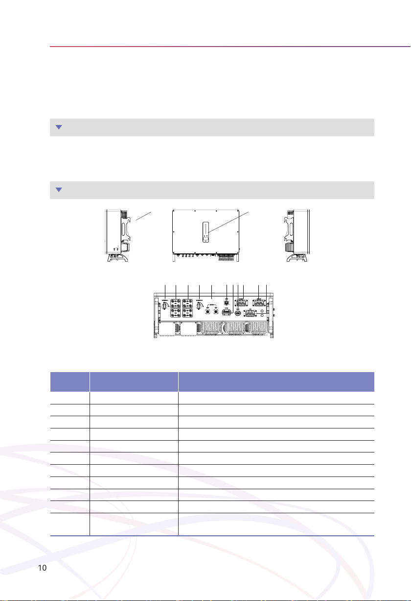
3.2.2 Appearance
3.2.1 Models
SG-25~50KWHBT
SG-25KWHBTSG-30KWHBTSG-36KWHBT SG-40KWHBT SG-50KWHBT
Item Terminal Note
1Display and LED panel Display the operation information and working states of the inveer.
2 Hanger Used to hang the inveer on the wall-mounting bracket.
3 DC switch Used to safely disconnect the DC circuit.
4 DC input terminal PV connector(SG-25~50KWHBT 8 pairs )
5 Batte input terminal Batte connector
6 COM1 po WiFi/LAN/4G module connector
7COM2 po Meter/BMS/RS485/DRED/DO Connector
8 COM3 po DO/0-10V AO/4-20mA AO Connector
9On-grid output terminal Used for On-grid output cable connection
10 Back-up output terminal Used for Back-up output cable connection
11 Generator input terminal Generator connector(This function is temporarily
unavailable. Please contact SOLARMG if necessary)
3.2 Product Introduction
SOLARMG SG-25~50KWHBT
-
to realize intelligent power management and dispatching.
1
2
3 34 4 56 8 97
3 4 4 3 9875 6
34 43 98756
43
12
871011
9
REV.1 – Preliminary
S.MG-UM:SG 25-50KWHBT

11
User Manual
SG-25~50KWHBT series
3.2.3 Indicator
Item Indicator Status Description
1Power and
Alarm Indicator
O No power.
Blue
Quick ashing Inveer entered self-test status.
Slow ashing Inveer entered waiting status.
Breathe ashing Inveer works normal.
Orange Breathe ashing Low batte warning, the batte power is
about to reach the SOC protection value.
Red Always on An alarm or fault is detected, view the fault
info on the display.
2Grid
Indicator
O Grid lost.
Slow ashing Inveer detected grid but not running in on-grid mode.
Always on Inveer works in on-grid mode.
3Communica-
tion Indicator
Green Always on The inveer communication is running nor-
mally.
Green Flashing The inveer communicates with EMS or
Master inveer through RS485 or CAN.
Orange Always on The inverter isn’t communicating with
smart meter.
Red Always on The inveer isn’t communicating with the
BMS.
4Display Display o to save power, press the button to wake up the display.
5Button Switch display information and set parameters by sho press or long press.
1
32
4
5
REV.1 – Preliminary
S.MG-UM:SG 25-50KWHBT
12
User Manual
SG-25~50KWHBT series
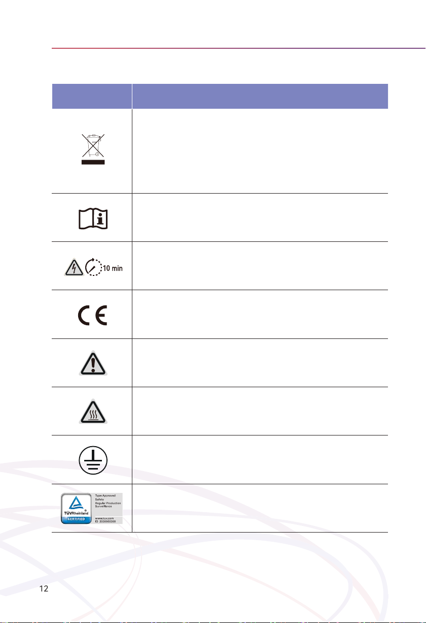
※ 3.3SymbolsOntheInveer
Symbol Description
To avoid the potential eects on the environment and human health as a result
of the presence of hazardous substances in electrical and electronic equipment,
end-users of electrical and electronic equipment should understand the meaning
of the crossed-out wheeled bin symbol. Do not dispose of WEEE as unsoed mu-
nicipal waste and have to collect such WEEE separately.
Please read the instructions carefully before installation.
Do not touch any internal pas of the inveer being disconnected from the mains,
batte and PV input for 10 minutes..
CE mark, the inveer complies with the requirements of the applicable CE guide-
lines.
Danger. Risk of electric shock!
The suace is hot during operation and do not touch.
Additional grounding point.
TÜV mark of conformity.
REV.1 – Preliminary
S.MG-UM:SG 25-50KWHBT
13
User Manual
SG-25~50KWHBT series
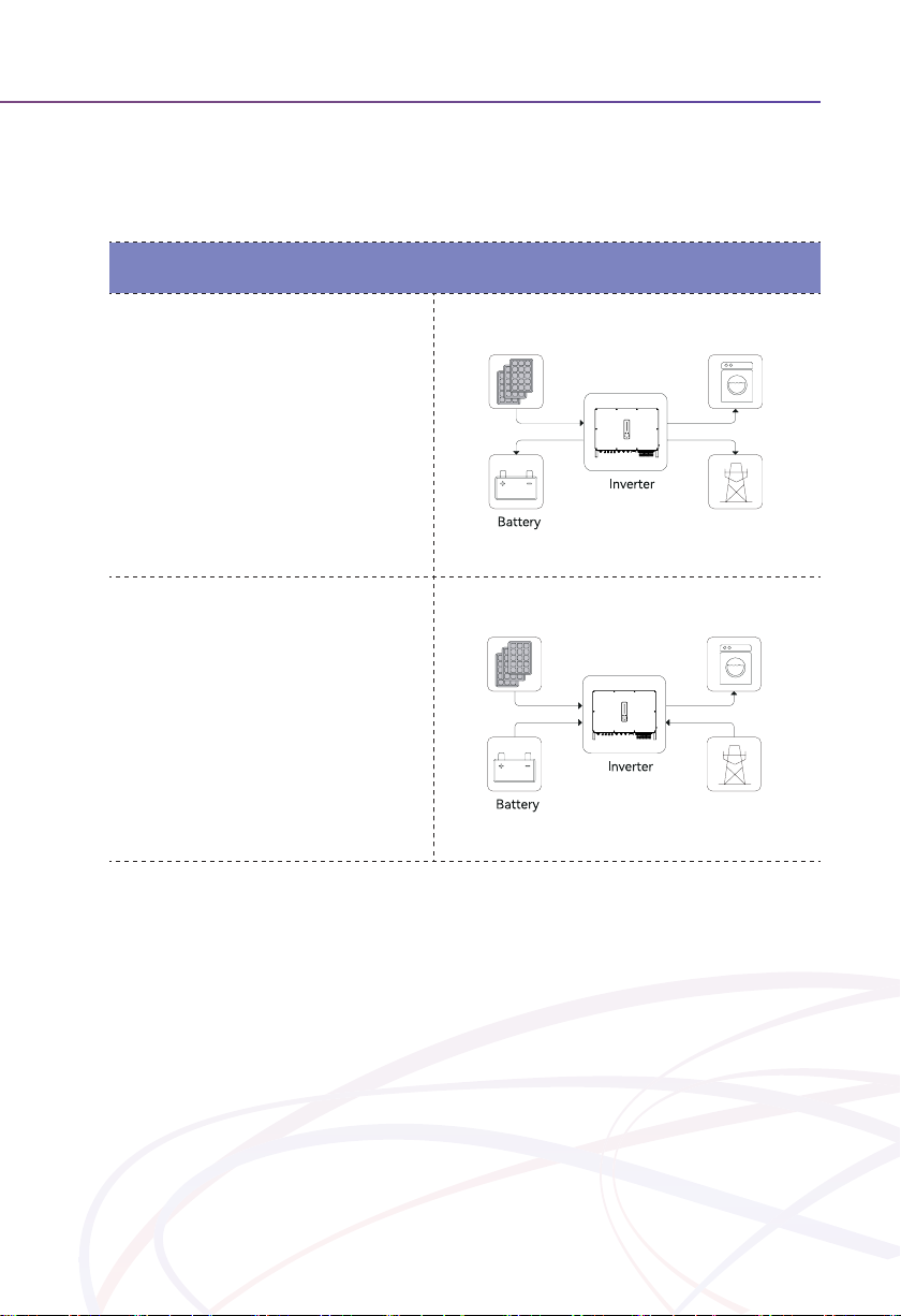
General Mode
In this working mode, when the power from the
PV array is sucient, PV power will supply the
loads, battery, and grid in the order ofloads
rst, batte second, and grid last.
(You can set the power to the grid to 0W when
the local grid doesn’t allow inverter power to
feed to the grid).
When the PV power is insufficient, the battery
will discharge to supply loads, and the grid will
join in if the battery is not enough to supply
loads.
PV Loads
Grid
PV Loads
Grid
※ 3.4 Operation Modes
SOLARMG -
ure the operation mode as per your preference in the App.
REV.1 – Preliminary
S.MG-UM:SG 25-50KWHBT

14
User Manual
SG-25~50KWHBT series
Peak load Shifting (Load Shifting)
Set the maximum power Pmax (kVA) contracted
with the grid.
When the load consumption is less than the
Pmax, the PV will charge the battery first, and
the grid supplies the load. When the batte is
full, PV will supply the load together with the
grid, but the batte doesn't.
When the load consumption exceeds the Pmax,
the inveer will take power from the batte and
PV to supply power to the load to compensate
for the power that exceeds the Pmax.
*To realize the “Peak load Shifting” function, the load power that exceeded Pmax has to be within the inveer
max output power, otherwise, the inveer will only output the max power which allowed.
PV Loads
Grid
PV Loads
Grid
Pload>Pmax
REV.1 – Preliminary
S.MG-UM:SG 25-50KWHBT

15
User Manual
SG-25~50KWHBT series
UPS Mode
In this working mode, the inverter will use the
power from PV or grid to charge the battery
until it is fully charged, and as long as the grid is
there, the batte won’t discharge.
When the grid fails, power from PV and batte
will supply loads connected on the back-up side
(UPS).
PV Loads
Grid
PV Back-up Loads
Grid
X
REV.1 – Preliminary
S.MG-UM:SG 25-50KWHBT

16
User Manual
SG-25~50KWHBT series
Economic Mode
In this working mode, you can set charge/dis-
charge power and time in the App, inveer will
use the power from PV or grid (whether to use
can be set in the App) to charge the batte in
the predetermined period.
Inveer will use power from PV and batte to
supply loads in the predetermined period and
the insucient pa will be supplied by the grid.
PV Loads
Grid
PV Loads
Grid
REV.1 – Preliminary
S.MG-UM:SG 25-50KWHBT

17
User Manual
SG-25~50KWHBT series
O-gridMode
In the purely o-grid mode, power from PV will
supply the back-up loads rst and then charge
the batte if there's surplus power.
When the power from PV isn’t enough, the
batte will discharge to supply back-up loads
together with PV.
PV Back-up Loads
No Grid
PV Back-up Load
No Grid
REV.1 – Preliminary
S.MG-UM:SG 25-50KWHBT

18
User Manual
SG-25~50KWHBT series
using the Back-Up function smoothly are as follows for your awareness.
①Do not connect loads that are dependent on a stable energy supply for a reliable opera-
tion.
②Do not connect the loads whose total capacity is greater than the maximum Back-Up
capacity.
③
④-
※ 3.5Back-UpandO-GridOutput
surges.
REV.1 – Preliminary
S.MG-UM:SG 25-50KWHBT

19
User Manual
SG-25~50KWHBT series
3.6.1 Packing List
accessories in the packing box are complete when receiving the goods.
DEF
GHI
ABC
※3.6 Unpacking and Storage
-
after receiving the device.
SOLARMG
REV.1 – Preliminary
S.MG-UM:SG 25-50KWHBT

20
User Manual
SG-25~50KWHBT series
Figure 3-5 Packing list
KL
Item Name and Quantity
AInveer (1pcs)
BInveer bracket (1pcs), Bolt assembly (4pcs), M6 screws (2pcs)
CAC connector set (3 pcs)
DPV terminal (SG-25~50K 8 pairs )
E Batte terminal (1 pairs)
FMeter with 3 CTs (1pcs)
G COM2 connector set (1pcs)
HCOM3 connector set (1pcs)
IMonitoring device (1pcs)
J10m meter communication cable (1pcs), 3m batte communication cable (1pcs)
KPE terminal(1pcs)
LUser guide
User
Manual
3.6.2 Inveer Storage
①Do not dispose of the original packing case. It is recommended to store the device in
the original packing case when the device is decommissioned.
②The storage temperature and humidity should be in the range of -30℃ and+ 60℃, and
less than 90%, respectively.
③If a batch of inveers needs to be stored, the height of each pile should be no more
than 4 levels.
J
REV.1 – Preliminary
S.MG-UM:SG 25-50KWHBT
This manual suits for next models
4
Table of contents
Other SOLARMG Inverter manuals


Popular Inverter manuals by other brands


INSBUD
INSBUD IB-INV-CSI manual

Sunforce
Sunforce 60 WATT SOLAR 12 VOLT POWER GENERATOR KIT user manual

Mitsubishi Heavy Industries
Mitsubishi Heavy Industries SRR25ZM-S Technical manual

Epever
Epever IP1500-Plus Series user manual

Mastervolt
Mastervolt WHISPER 12 ULTRA user manual

gefran
gefran AGy-EV Series instruction manual


