SOLARMG SG-5KWT User manual

3
REV.1-Preliminary S.MG-OM:SG 5-30T
Target Group
Scope
This manual describes the installation, electrical connection, commissioning and maintenance, APP
operation of the inverter. Please first read the manual and related documents carefully before using the
product and store it in a place where installation, operation and maintenance personnel can access it at
any time. The illustration in this user manual is for reference only. This user manual is subject to change
without prior notice.
Inverters must be installed by professional installers and electricians who have
obtained relevant qualifications from SolarMG. If the installation procedure is
carried out by other users, the warranty is not recognized.
Natural cooling series Fan cooling series
SG-5KWT
SG-6KWT
SG-8KWT
SG-10KWT
SG-12KWT
SG-15KWT
SG-17KWT
SG-20KWT
SG-22WKT
SG-25KWT
SG-30KWT
The following safety instructions and general information are used within this user manual.
DANGER
Indicates an imminently hazardous situation which, ifnot correctly
followed, will result in serious injury or death.
WARNING
Indicates a potentially hazardous situation which, if not correctly
followed, will result in serious injury or death.
CAUTION
Indicates a potentially hazardous situation which, if not correctly
followed, could result in moderate or minor injury.
NOTICE
Indicates a potentially hazardous situation which, if not correctly
followed, could result in equipment failure torun, or property damage.
NOTE
Call attention to important information, best practices and tips:
supplement additional safety instructions for your better use of the
inverter to reduce the waste of you resource.
Conventions
About This Manual

4
5
REV.1-Preliminary S.MG-OM:SG 5-30T
Preface 6. Startup/Shutdown Procedure
About This Manual
Target Group
Scope
Conventions
1.
Safety
1.1 Symbols Used
1.2 Safety Instruction
2.
Product Introduction
2.1 Product Overview
2.2 Product Appearance
3.
Unpack and Storage
3.1 Unpack and Check
3.2 Storage Inverter
3.3 Identify Inverter
4.
Installation
4.1 Selecting the Mounting Location
4.2 Mounting
5.
Electrical Connection
5.1 Grounding
5.2 AC Connection
5.3 DC Connection
5.4 Communication Connection
6.
1 Check before startup/shutdown procedure
6.2 Startup/Shutdown steps
6.3 Shutdown procedure
7.
User Interface
8.
Troubleshooting and Maintenance
8.1 Inverter Troubleshooting
8.2 Maintenance
8.2.1 Routine Maintenance
8.2.2 Fan Maintenance
8.2.3 Removing the Inverter
9. Technical Specifications
10.Technical Assistance
Contents
Contents

6
7
REV.1-Preliminary S.MG-OM:SG 5-30T
Before using the inverter, please read all instructions and cautionary markings on the unit and manual.
Put the instructions where you can take them easily.
The inverter of us strictly conforms to related safety rules in design and test. Local safety regulations
shall be followed during installation, operation and maintenance. Incorrect operation work may cause
injury or death and damage to the inverter and other operator or a third party.
To avoid injury and damage to the inverter and other operator, please follow the safety precautions.
1.1 Symbols Used
The sign of caution stick on inverter.
1.2 Safety Instruction
Installation and maintenance of inverters must be performed by qualified personnel, in accordance with
local electrical standards, wiring regulations and requirements of local power authorities.
To avoid electric shock, DC input andAC output of the inverter must be terminated at least 10 minutes
before performing any installation or maintenance.
The temperature of some parts of the inverter may exceed 60℃ during operation, do not touch the
inverter during operation to avoid being burnt.
Ensure children are kept away from inverters.
Take appropriate measures to avoid electric shock.
Don’t open the front cover of the inverter. Apart from performing work at the wiring terminal,
touching or changing components without authorization may cause injury to people, damage to
inverters and annulment of the warranty.
Ensure the output voltage of the proposed PV array is lower than the maximum rated input voltage of
the inverter; otherwise the inverter may be damaged and the warranty annulled.
When exposed to sunlight, the PV array generates dangerous high DC voltage. Please operate according
to our instructions, or it will result in danger to life.
Don’t insert or pull the terminals when the inverter is running.
Safety Symbol
Description
Danger of high voltage!
Only qualified personnel may perform work on the inverter.
5 mins
Danger of high voltage. Residual voltage in the inverter need
5 mins to discharge, wait 5 mins before operation.
Danger of hot surface
Fire danger
Environmental Protection Use Period
Refer to the operating instructions
If the inverter service life has expired, dispose it in accordance with
local rules for disposal of electrical equipment waste. Do not dispose
the PV inverter with household garbage.
Grounding terminal

8
9
REV.1-Preliminary S.MG-OM:SG 5-30T
Transformer
Transformer
Transformer
Transformer
L1 L1
L2 L2
L3 L3
N PEN
PE
L1
L2
L3
N
PE
L1
L2
L3
N
PE
PE
Inverter
PE
Inverter
PE
Inverter
PE
Inverter
TN-S
TN-C
TN-C-S
TT
Number Description
2.1 Overview
The three-phase grid-tied PV inverter converts the DC generated by PV panels into three-phase
alternating current and is delivered to the grid.
This series inverter is an important part of PV system and it is suitable for household use,
commercial use, fishery use, agricultural use and other scenarios.
2.2 Product Appearance
The following is only for reference, specific please in kind prevail.
This series inverter is suitable for TN-S, TN-C, TN-C-S and TT grid system. Refer to the following figures:
1 2 3 4
Natural cooling series Fan cooling series
1DC Switch
2LED Indicators
3LCD Screen (Optional)
4External ground terminal
PV strings
Inverter
AC Distribution Unit
Grid
(Only take fan cooling as an example in appearance)
208.5mm
190.5mm
414.27mm
398mm
(Only take natural cooling as an example in appearance)
460mm
480.5mm

10
11
REV.1-Preliminary S.MG-OM:SG 5-30T
Contact your dealer immediately if there is any issue found during operation.
NOTICE
Natural cooling series
Fan cooling series 1
5 6 7 8
9
Fan cooling series 2
3.1 Unpack and Check
Complete test and strict inspection shall be done before the inverter is sent out.
When receiving the inverter, check that the packing materials are intact.
After unpacking, examine the PV inverter and its fittings for damage and check that the deliverables
are complete.
5PV terminal
6RS485 communication port
7WiFi/GPRS/LAN model communication port(Optional)
8AC output port
9External fan(It is only suitable for Fan cooling series)
Number
Description
Quantity
A
The Inverter
1
B
Bracket
1
C
AC shield(4× M4 security screws)
1
D
PV connectors
2 or 4
E
File package
1
F
Expansion screws groups
3
G
M6 Security screw
2
H
6-Pin terminal
2
I
WiFi/GPRS/LAN module (Optional)
1 (Optional)
J
Remove tool for PV connector
1 (Optional)
K
RS485 cover
1
Number Description
A
B
C
D
E
Or
F
G
H
I
J
K
Or
Unpack and Storage
12
13
REV.1-Preliminary S.MG-OM:SG 5-30T
3.2 Storage Inverter
If the inverter is not used immediately, please keep the inverter in a specific environment according to the
following requirements:
Do not unpack the inverter and put desiccant in the original box if the PV inverter is unpacked.
Store temperature range: -25°C~+60°C; Relative humidity range: 0~100%.
Don’t position the inverter leaning forward, excessively leaning backward, tilting laterally, or upside down.
Ensure that qualified personnel inspect and test the inverter before use if it has been stored for a long time.
After checking the outer packing, move the PV inverter to the designated installation position horizontally.
3.3 Identify Inverter
Inverter body label. The following is only for reference, specific please in kind prevail!
1Product name and model
12Product technical parameters
3SN Barcode
4Approve and Safety identification
2
3
4
4.1 Selecting the Mounting Location
4.1.1 Installation Environment Requirements
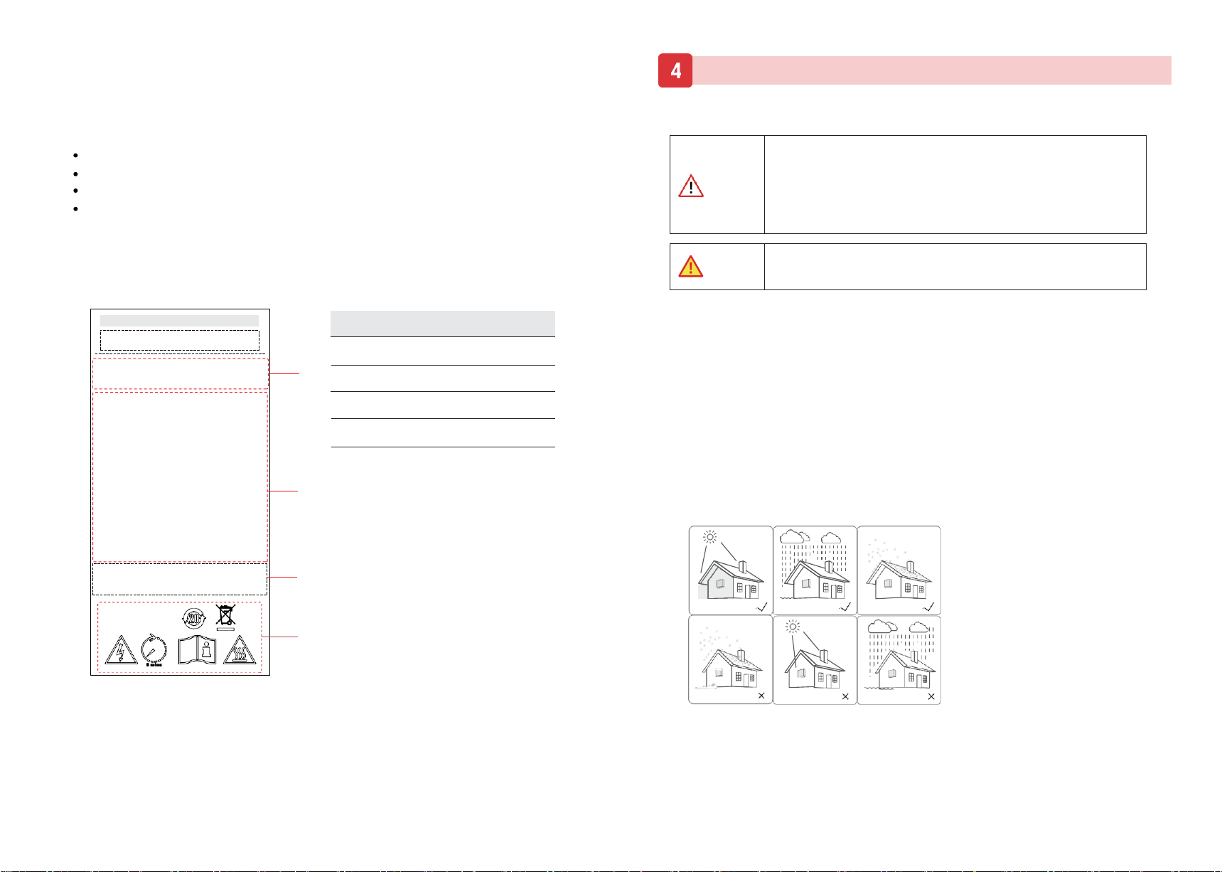
a. The storage inverter protection class is IP65 and can be mounted indoors or outdoors.
b. To ensure optimum operation and long service life, the ambient temperature must be below 50℃.
c. Do not install the inverter in a rest area since it will cause noise during operation.
d.The inverter carrier must be fire-proof. Do not mount the inverter on flammable building materials.
e. Ensure that the wall meets the requirements of the inverter installation.
f. Product label and warning symbols shall be clear to read after installation.
g. The installation height should be reasonable and make sure it is easy to operate and view the display.
h. Please avoid direct sunlight, rain exposure, snow lay up.
Max.Input Voltage:
Input Voltage Range :
Max.Input Current:
Input Short Circuit Current:
Rated Output Voltage :
Rated Output Frequency:
Max.Output Current :
Rated Output Power:
Max.Apparent Power:
Adjustable Power Factor Range:Enclosure
:
Temperature Range:
Protective Class:
Product Name :
Product Model:
Number Description
DANGER
CAUTION
No direct sunlight No rain exposure
No snow lay up
Snow lay up
Direct sunlight
Rain exposure
Installation
Ensure there is no electronical connections around ports of the PV inverter
before installation.
1. Please place the inverter horizontally on the foam or other soft pads and
ensure that the ports are free of load-bearing pressure to avoid inverter
damages or scratches.
2. The inverter is heavy, be careful to prevent the inverter from slipping
and hurting the operator when moving the inverter.
14
15
REV.1-Preliminary S.MG-OM:SG 5-30T
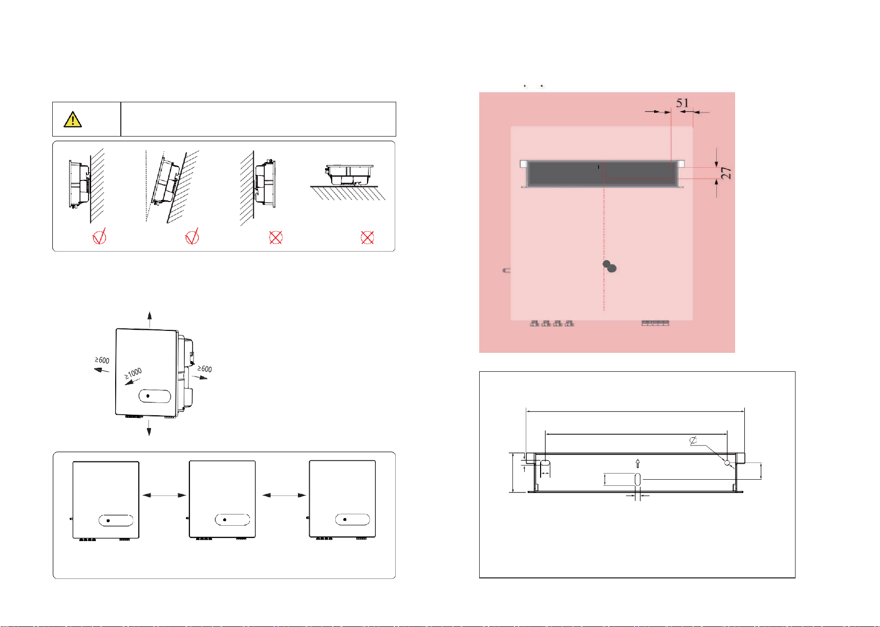
≤15°
Upright
Lean back ≤15°
Upside-down
Horizontally
600mm
600mm
Installation along the same line for multiple inverter
(Only take fan cooling as an example in appearance)
4.1.2 Mounting Requirements
Mount the inverter vertically or tilted backward by max 15°. In order to facilitate the heat dissipation of
the inverter.
Installation perspective schematic
4.1.3 Installation Space Requirements
To ensure the operation of the inverter normally and easily, there are requirements on available spaces
of the inverter, e.g. to keep enough clearance. Refer to the following figures.
≥600
Above: 600mm
Below: 600mm
Front: 1000mm
Both sides: 600mm
≥600
The wrong installation mode causes the inverter to be damaged or unable to
work properly.
NOTICE
354
294 8
15
8
Unit: mm
Bracket plane size drawing
64
8
20
27
16
17
REV.1-Preliminary S.MG-OM:SG 5-30T
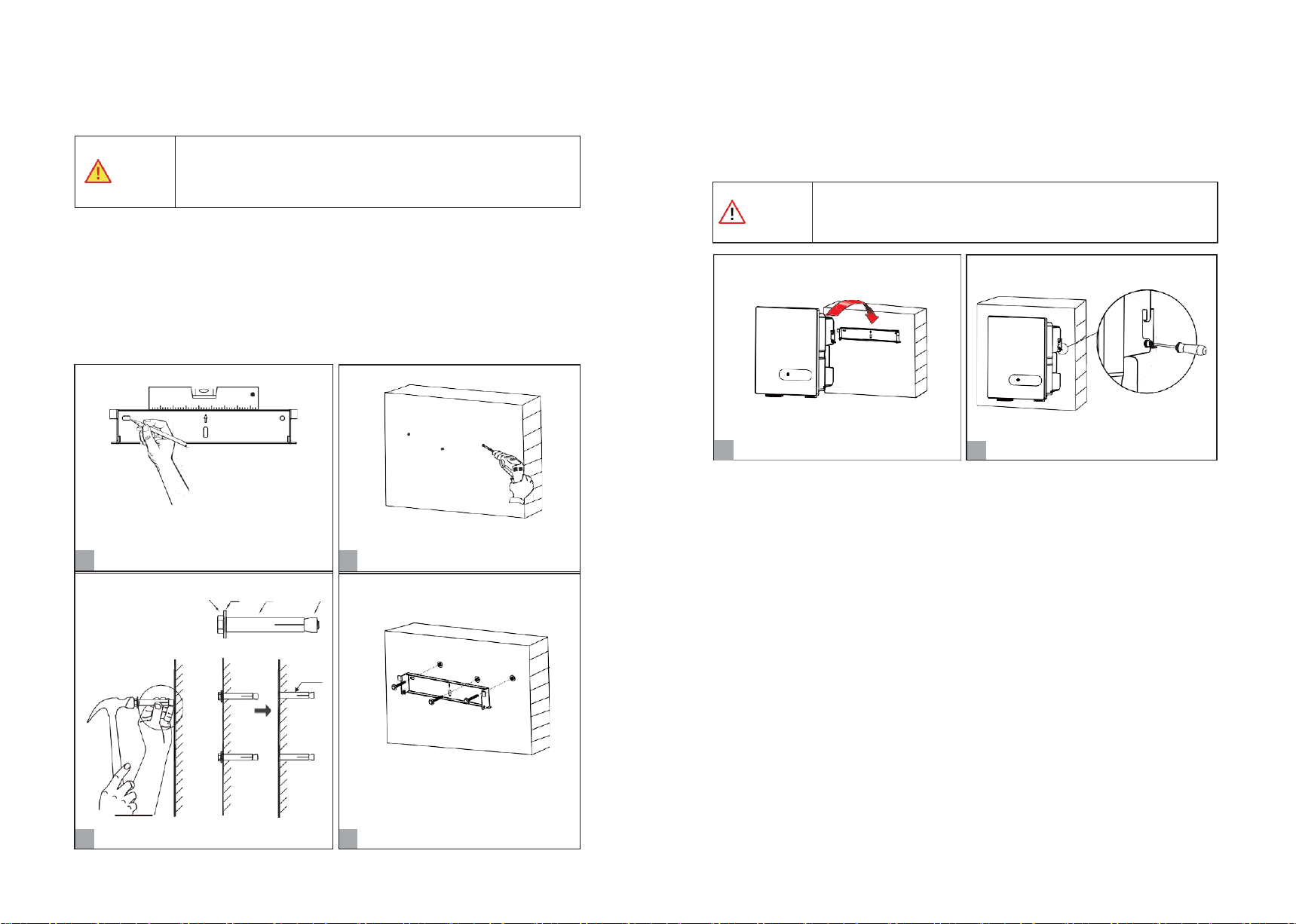
Set bracket horizontally.
1
Mark the holes position on the wall.
A
B
C
D
Expansion screw group
(M6; 3 suites)
C & D
3
Install the expansion screw
Ø:10mm; Depth: 60mm
2
Drill the holes.
M6 Expansion screws; 2~2.5N·m
4
Install bracket.
4.2 Mounting
Step 1. Install the mounting bracket Step 2. Install the inverter.
Install the inverter on the bracket accurately and tighten the screws at both sides, as shown in Step 5 and
Step 6.
1 ) Use a horizontally ruler to mark the position of the 3 holes on the wall. Refer to Step 1. And drill 3 holes,
10mm in diameter and 60 mm in deep. Refer to Step 1 and Step 2.
2)Knock the expansion screw kit into the hole together with a hammer. Refer to Step 3.
Note: Do not remove the nut unit.
3)After tightening 2-3 buckles, the expansion bolts are tight and not loose, and then unscrew the bolts,
spring washer, gasket. Refer to Step 3.
4) Install the bracket on the wall, the bracket screw is pointed at the expansion tube on the wall, then install
the gasket and tighten screw. Refer to Step 4.
CAUTION
DANGER
Install the inverter.
5
To prevent damage of the inverter, please hang the inverter on the bracket
and confirm the reverse, do not loosen the handle until the inverter is fixed.
1.The walls must be fireproof and non-flammable materials, otherwise there
is a fire risk.
2.Before drilling holes ,check whether there are electric power pipes buried
in the walls to avoid risks.
2×M6 screw; 3N·m
6
Tighten the screws at both sides.
18
19
REV.1-Preliminary S.MG-OM:SG 5-30T
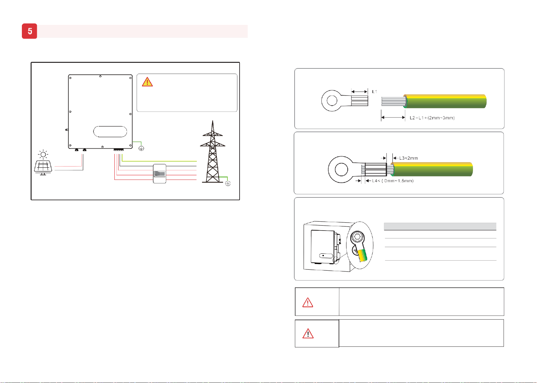
Step2.Insert the exposed core wires into the crimping areas of the OT terminal and crimp them
using hydraulic pliers.
Step3.Remove the ground screws from the ground points.
Screw M6 × 12mm; 3 N·m
OT Terminal OT6-6(5K-15K); OT16-6(17K-25K)
Yellow green lines S(Yellow green lines) ≥S(PE line of DC cable)
S is the cross-sectional area.
Ensure that the grounding resistance is less than 10Ω.
Items Remark
According to regulations, the secondary protection grounding can’t replace
the PE terminal connection of the AC cable. Ensure that both are grounded
reliably. Otherwise, fatal injury can occur due to the high voltage.
WARNING
If the positive pole or negative pole of the PV array is required to be
grounded, then the inverter output (to AC grid) must be isolated by
transformer in accordance with IEC63109-1,-2 standards.
System Connection
5.1 Grounding
According to the EN50178 requirement, the right side of the device has a protective grounding connection.
Be sure to connect the protection ground cable to this port when installing the inverter.
The user can perform the ground connection according to the on-site condition.
Step1.Remove an appropriate length using a wire Stripper.
CAUTION
L1L2L3 N PE
PE
PV+
PV-
PE
N
L3
L2
L1
Grid
PE
DANGER
Before electrical connection, please ensure
that both the AC and DC ends are powered off,
otherwise there will be a high voltage shock.
Electrical Connection

20
21
REV.1-Preliminary S.MG-OM:SG 5-30T
Multiple inverters are not allowed to share a circuit breaker.
Load is not allowed to connect between the inverter and the AC breaker.
WARNIMG
Inverter Model Recommended Value
5.2 AC Connection
5.2.1 AC cable connection
1. Measure and access the voltage and frequency of the point to ensure that it meets the grid-tied
specifications of the inverter.
2. PE wire(GND) must be well grounded to ensure that impedance between Neutral wire and Earth
wire is less than 10Ω.
3. Disconnect the circuit breaker or fuse from the inverter and grid-connected access point.
4. Use the copper wire.
5. Follow these steps.
Nut
Torque
②5K-15K M25 5.5N·m
17K-25K
M40 12N·m
①4×M4
screws;1.2N·m
①Align the AC cover with the 4 holes and tighten it firmly with 4×M4 screws.
4
②Fasten the nut(waterproof cap).
5.2.2 AC Breaker and Leakage current protector
To ensure that the inverter disconnect from the grid of safely, the independent AC breaker must be
configured for each inverter as a protective device.
SG-5KWT,SG-6KWT,SG-8KWT 20A
SG-10KWT,SG-12KWT 32A
SG-15KWT,SG-17KWT 40A
SG-20KWT 50A
SG-22KWT,SG-25KWT 63A
Internal current detection equipment for inverter, the inverter detects the leakage of the power grid
that is greater than the reduced value, and will be disconnected quickly from the power grid. If the
external installation leakage protection device is installed, Its action electricity must be greater than
equal to 300mA.
No. Name Model 5K-15K 17K-20K 22K-25K
100mm(Recommended)
L+2mm L AWire outer diameter(mm) 11-18 24-32 24-32
B Cross-sectional Range 4-6 6-16 10-1
area(mm²) Recommended 6 10 16
A B Note: It is recommended to use outdoor dedicate cables
with multiple copper cores.
1
Select proper AC cables and OT terminals (5 wires)
Heat shrinkable tube
Unscrew the nut of the cover and thread the AC cable (5 wires) cross the nut, threaded sleeve and the
cover. Then crimp the OT terminal and use heat shrink tubing or insulation tape for protection.
2
Wires threading and pressing.
3
Lock the AC cable to the corresponding AC terminals.
D
L1 L2 L3 N PE
Screw Torque D
5K-15K
M4 1.5N·m 10mm
17K-25K
M5 3N
·
m
12.5mm
(Only take 25k model as an example)
22
23
REV.1-Preliminary S.MG-OM:SG 5-30T
5.3 DC Connection Before connecting the PV input to the inverter, ensure that the package meets the following
electrical specifications.
All 1100V 20A
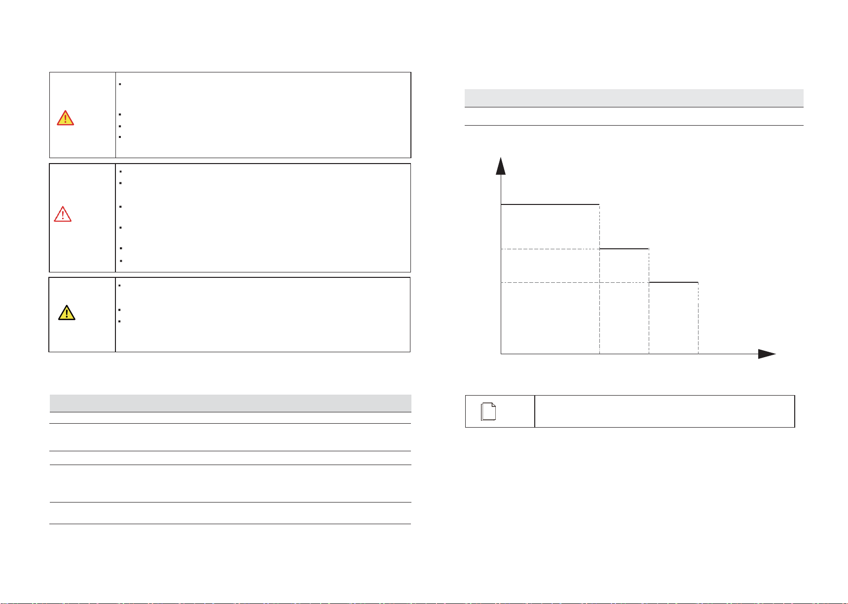
Open-circuit voltage altitude derating curve of the inverter as shown in the following figure
1100V
950V
850V
.
5.3.1 Preparation
Different PV module input configuration model table (All PV strings are connected to the inverter in the
corresponding groups number)
2000m 3000m 4000m
Open-circuit voltage altitude derating curve of the inverter
SG-5KWT, 6KWT PV strings circuit<15A,All PV strings are connected into one group
SG-8KWL, 10KWT PV strings circuit<12A,All PV strings are connected into two groups
PV strings circuit>12A,All PV strings are connected into one group
SG-12KWT, 15KWT PV strings circuit≤15A,All PV strings are connected into two groups
SG-17KWT, 20KWT PV strings circuit<12A,All PV strings are connected into four groups
PV strings circuit≥12A≤15A,All PV strings are connected into three groups
PV strings circuit>15A,All PV strings are connected into two groups
SG-22KWT, 25KWT All PV strings are connected into four groups
Inverter model PV input configuration
Inverter model Limit of each input open-circuit voltage Maximum allowable input terminal current
DANGER
PV modules generate electric energy when exposed to sunlight and can create an
electrical shock hazard. Therefore, when connecting the PV modules, shield them
with opaque cloth and ensure that DC switches are OFF.
To avoid electric shock, don’t touch the charge part and connect the terminals carefully.
Before connecting power cables, ensure the AC/DC switches are OFF.
When the inverter is connected to the grid, don’t plug in or plug out the PV strings.
Don’t perform any operation until the inverter is shut down.
PV modules connected in series in each PV string must be of the same specifications.
The maximum open-circuit voltage of each PV string must be always lower
than or equal to its permitted range.
The maximum short circuit current of each PV string must be always lower
than or equal to its permitted range.
Ensure that the positive and negative terminals of each PV strings connected to the
inverter correctly.
The positive or negative terminals of PV strings can’t be connected with short circuit.
The totaloutput power of all PV strings can’t exceed the maximum input powerof the inverter.
WARNING
The positive and negative terminals of PV modules can’t connect to PE wire(GND) ,
otherwise, the inverter will be damaged.
Ensure that the voltage of each PV string doesn’t exceed 1100V under any circumstances
When the input voltage is 1000V to 1100V, the inverter will enter the standby state.
When the voltage returns to the MPPT operating voltage, namely 160V-1000V, the
inverter will return to the normal state.
NOTICE
Elevation(m)
NOTE
To ensure that the inverter reaches the enclosure of IP65, it can only
use the connector provided by supply.

24
25
REV.1-Preliminary S.MG-OM:SG 5-30T
5.3.2 PV Connection
PV connection please refer to below.
5.4 Communication Connection
5.4.1 Communication Mode Description
You can use the following communication modes to implement communication:
Bluetooth, WIFI, GPRS and RS485 which are described as follows.
Bluetooth Module
You can turn on the Bluetooth function of the mobile phone, and set parameters and monitor data
of the inverter through the mobile APP.
WIFI/GPRS/RS485 Modules
Through DB9 communication interface is transferred to other communication modules to monitor
the inverter. The module and functions are shown in Table 5.4.
Module
Function description
WIFI
WIFI module implements communication with Cloud server through wire and
wireless network to monitor PV inverter’s data status. For more details, refer to
WIFI Product Application Manual.
GPRS
GPRS module implements communication with Cloud server through wire and
wireless network to monitor PV inverter’s data status. For more details, refer to
GPRS Product Application Manual.
RS485
RS485 switching module monitors PV inverter's data status through collecting
and uploading data to Cloud server.
Table 5.4 Communications module description
5.4.2 WIFI/GPRS/LAN Module Connection(Optional)
WiFi/GPRS/LAN module connection please refer to below.
For details about APP settings, see the WIFI/GPRS/LAN Module Installation Guide in the packing case.
Loosen screws and
Install the GPRS/WiFi/LAN module,
2 × M4 screw; 0.8N·m
or
or
Tighten the
GPRS/WiFi/LAN
1
move the cover.
2
make sure doesn’t fall off naturally.
3
module and install antenna.
8~10mm
Limit buckle
Positive Connector
Click
Diameter
5~8mm
8~10mm
Use crimping tool
to stitch.Limit buckle
can’t be crimped.
Negative Connector
~
~
~
~
Tighten the waterproof nuts
on each connector with a wrench
to avoid loosening.
Test string voltage and confirm string polarity. Ensure that the DC switch is OFF.
Note: DC cable should be dedicate PV cable(suggest using 4~6mm² PV1-F cable).

26
27
REV.1-Preliminary S.MG-OM:SG 5-30T
Pin Inverter
2 × M4 screw; 0.8N·m
A
B
A
B
PE
PE
DO1
ALM
SIG
D12
D11
GND
COM2
0.8~1.5N·m
≤60mm
8mm
Threaded sleeve
RS485Communication
cable (22AWG)
Wire stripping pliers are used to hold the wire, and
then the two nuts on the protective cover are lowered
to pass the communication wire through the nut,
threaded sleeve and main body of the protective cover.
1 Connect the different positive and negative signal
Nut
2
3 wires of the first RS485 cable from the data logger to
4
5 Pin1 and Pin2 of the 6-Pin terminal respectively. If
6 there is more than one inverter, connect Pin3 and Pin4
to Pin1 and Pin2 of another inverter terminal.
2
4
3
1
1A
2B
3A
4B
5
PE
6
PE
1
DO1
2
ALM
3
EXT_SIG
4
DI2
5
DI1
6
GND
5.4.3 RS485 Connection
The multiple inverter network and RS485 communication are as follows:
Install RS485 following this steps:
Step1 Loosen screws and remove the cover plate.
Step2 Wires making, threading and wiring.
Step3 Insert the 6-Pin terminal into the RS485 communication port.
Step4 Install the RS485 cover.
Step5 RS485 communication address setting.
Pin1 and 2
Pin3 and 4 Pin1 and 2
Pin3 and 4 Pin1 and 2
Data Logger
5
① Download the APP in either of the following ways
Scan the QR code on the inverter to download the APP
Download the APP from the APP store or Google Play.
Note: You need to grant all access rights in all pop-up windows when installing the APP or setting your phone.
②Power on the inverter.
③ Connect the inverter. Open the Bluetooth on your phone, then open the APP.
Then follow the instructions below:
XXXXXXXX
0.00Wh
0.00kWh
Scanningmachine SN barcode E-Today E-Total
Put the bar code into the box and it can be
scanned automatically. 0.00W 0.00W
If you cannot recognize or have no barcode,
select “Manual Connect”. 0.00W
Can not find inverter code
ManualConnect Basic
Inverter List Current PIonwvererter Time Wrong 0.00W
New inverters Choose and click the inverter PeaDkoPoywoeur want to synchronize date 0a.n0d0W
No new device... you want to connect. E-Ttoimdaeywith the mobile phone? 0.00Wh
E-Total 0.00kWh
Connected inverters CANCEL OK
Temperature -20.00℃
xxxxxxx DC-Input
xxxxxxx
i
Quick Setup Chart Home Log Console
④ Go to Console>Communication Setting > RS485 Setting > Modbus Page, check the Modbus address(the default
value is 1),and click to modify the address as required if necessary.
28
29
REV.1-Preliminary S.MG-OM:SG 5-30T
6.1 Check before startup/shutdown Procedure
Check following this steps after installation.
1The inverter is firmly installed.
2There is enough heat dissipation space, no external objects or parts left on the inverter.
3It is convenient for operation and maintenance.
4The wiring of the system is correct and firm.
5Check whether the DC and AC connection are correct with a multimeter, and whether
there is a short circuit, break, or wrong connection.
6Check whether the waterproof nuts of each part are tightened.
7The vacant port has been sealed.
8All safety labels and warning labels on the inverter are complete without occlusion
or alteration.
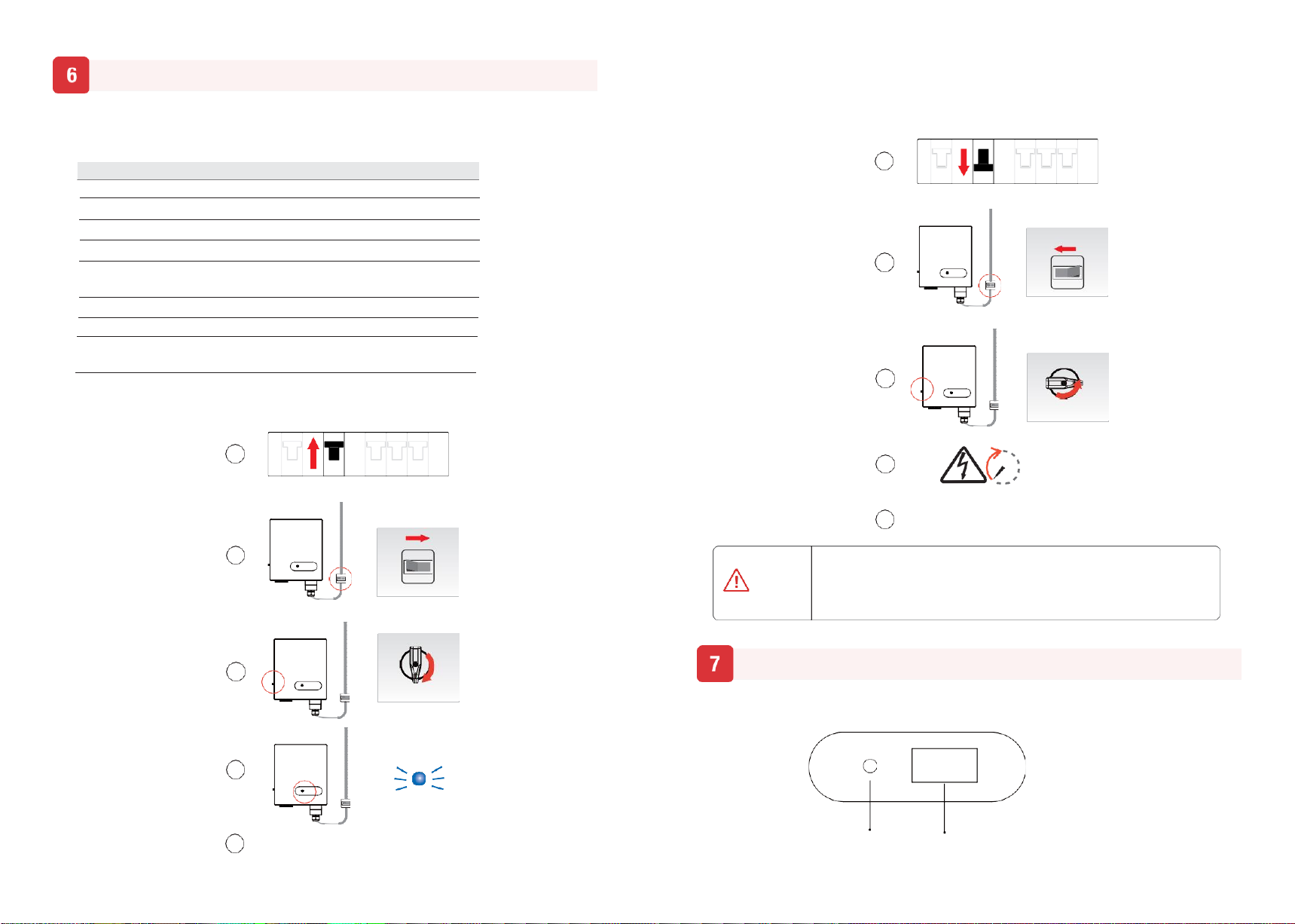
6.2 Startup Procedure
Startup procedure following the procedures :
Supply Main Switch
6.3 Shutdown Procedure
It may be necessary to shut down the inverter sometimes during the daily use. If necessary, please
follow the procedures:
Supply Main Switch
See if there’s any on site
(The figure is only for reference)
AC Circuit Breaker
Switch to OFF
(The figure is only for reference)
DC Switch
Switch to OFF
See if there’s any on site
(The figure is only for reference) Wait at least 5 minutes
Letinverter fully
heat dissipation.
AC Circuit Breaker
Switch to ON
(The figure is only for reference)
DC Switch
Switch to ON
Finishing
Your system has shutdown
LED icon
Blue on (normal status)
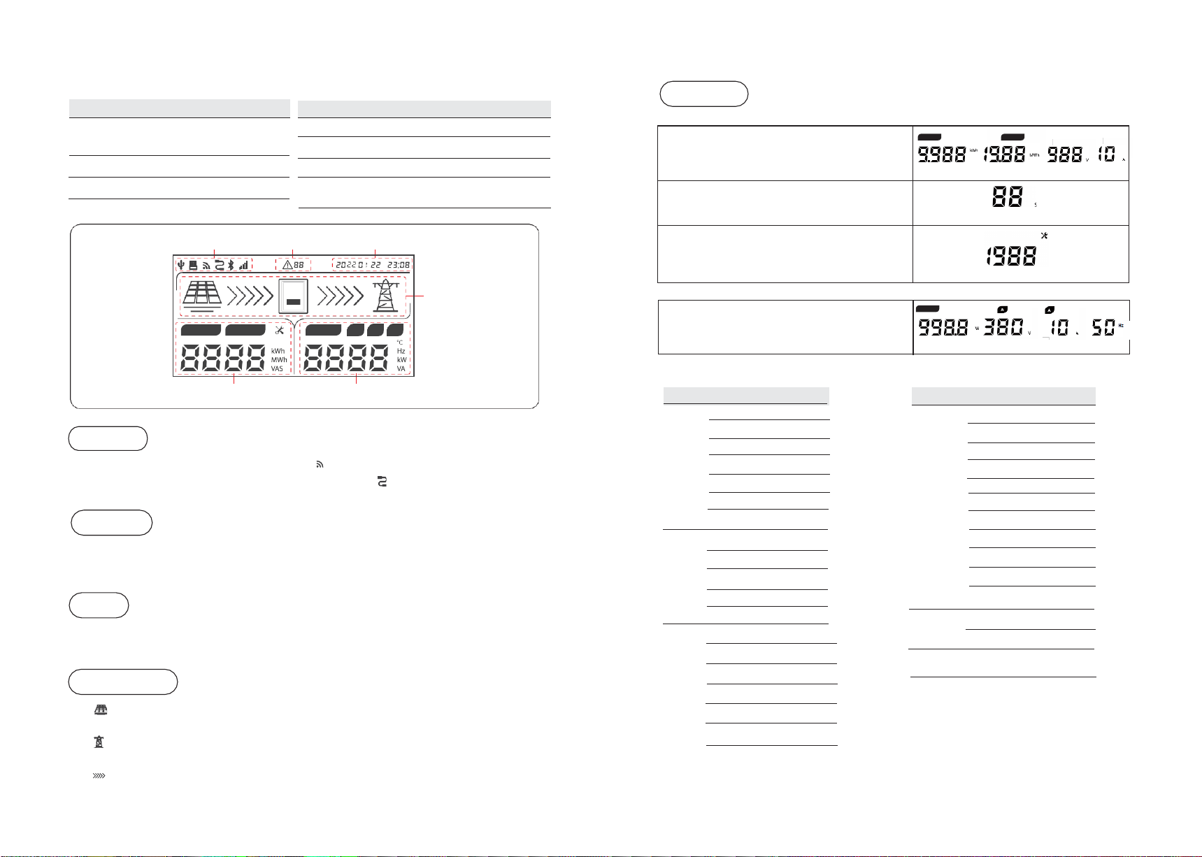
Inverter display panel is consist of LED icon and LCD(Optional).
Finishing
Your system has started up
LED icon LCD(Optional)
No. Items
OFF
ON
OFF
ON
After the inverter is powered off, the heat sink generates heat and there is
excess electricity in the inverter. To avoid electric shocks and burns, powered
off inverter for at least five minutes before performing operations.
WARNING
1
2
3
4
5
4
5 mins
OFF
ON
1
OFF
ON
2
3
5
Startup/Shutdown Procedure
User Interface
30
31
REV.1-Preliminary S.MG-OM:SG 5-30T
Power
Normal status: output power, grid voltage
and current are showed in turn.
COM
Table 7-1 LED status descriptions
Blue led blink Standby or startup state
slowly 1s/time (not connected to the grid)
Blue on Grid-tied status
Green on Power limited status
Red led blink slowly 1s/time Output side fault
Red led blink quickly 0.25s/time Input side fault
Red led on System internal fault
Red/Green/Blue light Burning code(Master/Slave)
alternately (1 color /0.25s) Control power setup (lasts1second)
Warning Table
Figure 7-2 LCD Screen
When WIFI/GPRS/Bluetooth is transferring data, icon will be ON, while no data transmission,
the icon will be off after 10s. When RS485 is transferring data, icon will be ON, while no data
transmission, the icon will be off after 10s.
When warning is triggered, icon will be illuminated: from left to right the first bit could be A/ B/ C,
it stands for warning type, and the second bit is warning code, please refer to warning code in table
for details.
Red
blink
slowly
Red
blink
quickly
Grid over voltage A0
Grid under voltage A1
Grid absent A2
Grid over frequency A3
Grid under frequency A4
Grid abnormal A6
Grid high average voltage A7
PV over voltage B0
PV Insulation resistance abnormal B1
Leakage current abnormal B2
PV Strings abnormal B3
Red on
System type error C7
DC link voltage unbalanced C9
DC link over voltage CA
Internal communication error CB
Software incompatibility CC
EEPROM error CD
Consistent warning CE
Inverter abnormal CF
Boost abnormal CG
Master Lost CH
Meter lost CJ
When external communications is normal and time zone is set correctly, the built-in clock of
inverter will be synchronized with server’s time. Without external communications, it is recommended
to use the mobile app to set up time through connecting Bluetooth to the inverter.
PV under voltage B4
Control power abnormal C0
Arc fault C1
Blue
blink
Fan abnormal (standby) C8
Remote off CN
High DC component of output current C2 Blue on Fan abnormal(normal status) C8
Icon stands for PV strings, when inverter is standby status, MPPT voltage of the PV string
will be displayed in Meter zone.
Icon stands for grid, when voltage and frequency of power grid is in normal range, the icon
keeps on, or else, it blinks; when there is no voltage, the icon will be off.
Icon stands for energy flow, when inverter is in normal status, the icon will be on, or else it
will be off.
Red on
Inverter relay abnormal C3
Inverter over temperature C5
Leakage current HCT abnormal
C6
Note: If you select a machine with a LCD screen,the warning code will be
displayed on the LCD screen.Non-lcd screen models need to enter the app
to view the corresponding warning code.
Warning
Status Details Warning code
Status Details Warning code
LED status Descriptions
LED status Descriptions
COM
Warning
Date
Status
E-Today
E-Total
Power
A B C
Meter
Output
Status
Date
Meter
Normal status: today and total energy, MPPT
voltage and current are showed in turn.
E-Today E-Total
Standby status: counter down value before
inverter start up.
Any status: setting parameters via APP, the
screen keep for 5 seconds.
32
33
REV.1-Preliminary S.MG-OM:SG 5-30T
Before maintaining and commissioning inverter and its peripheral distribution unit,
switch off all the charged terminals of the inverter and wait at least 10 minutes after
the inverter is powered off, otherwise there will be a high voltage shock..
WARNING
Wrong maintenance will result in personnel injury or equipment damage!
Before performing any maintenance operations, you must follow these steps:
First, disconnect the AC circuit breaker on the grid side, and then disconnect
the DC switch.
Wait at least 10 minutes after the inverter is powered off, otherwise there will be a
high voltage shock.
Use testing equipment to make sure there no voltage or current.
DANGER
NOTICE
Comply with ESD protection specifications and power distribution ESD bracelets.
Avoid unnecessary contact with the circuit board.
Touching printed circuit boards or other electrostatic sensitive components may
cause damage during the process.
8.1 Troubleshooting
If the inverter is break down, the LED indicator will turn to red.
Alarm Information
Measures Recommended
A0-Grid over
voltage
1.
If thealarmoccurs accidentally, possibly the power grid is abnormal accidentally. No extra action is
needed.
2.
If the alarm occurs repeatedly, contact the localpower station. After receiving approval of the local
power bureau, revise the electrical protection parameters setting on the inverter through APP.
3.
If the alarm persists for a long time, please confirm:
1)
The AC circuit breaker does not jump frequently (the instantaneous high pressure);
2)
If the line of communication is followed by the user manual, the cable impedance will cause the power
grid to rise;
3)
The three-phase machine measures whetherthe voltage between the zero line and the ground line exceeds
30V; More than the wiring of the grid;
If there is no problem, Please contact the customer service center.
A1-Grid under
voltage
1.
If thealarmoccurs accidentally, possibly the power grid is abnormal accidentally. No extra action is
needed.
2.
If the alarm occurs repeatedly, contact the localpower station. After receiving approval of the local
power bureau, revise the electrical protection parameters setting on the inverter through APP.
3.
If the alarm persists for a long time, please confirm:
1)
AC circuit breaker is disconnect or not;
2)
Whether the AC circuit breaker is damaged (whether the voltage in the closed state is consistent with the
voltage of the outlet);
3)
The AC terminals are in good contact.
If the actual measuring voltage is within the specification range, please contact the customer service report
repair.
Troubleshooting and Maintenance
A2-Grid absent
1.
If the alarm occurs accidentally, possibly the power grid is abnormal accidentally. No extra action is
needed.
2.
If the alarm occurs repeatedly, contact the local powerstation. After receiving approvalof the local
power bureau, revise the electrical protection parameters setting on the inverter through APP.
3.
If the alarm persists for a long time, please confirm:
1)
AC circuit breaker is disconnect or not;
2)
Whether the AC circuit breaker is damaged (whether the voltage in the closed state is consistent with the
voltage of the outlet);
3)
The
AC terminals are
in
good contact;
4) Whether the power supply line failure.
If exclude all possibility, please contact the customer service report repair.
A3-Grid over
frequency
1.
If the alarm occurs accidentally, possibly the power grid is abnormal accidentally. No extra action is
needed.
2. If the alarm occurs repeatedly, contact the local power station. After receiving approval of the local power
bureau, revise the electrical protection parameters setting on the inverter through APP.
A4-Grid under
frequency
1.
If the alarm occurs accidentally, possibly the power grid is abnormal accidentally. No extra action is
needed.
2.
If the alarm occurs repeatedly, contact the local powerstation. After receiving approvalof the local power
bureau, revise the electrical protection parameters setting on the inverter through APP.
3.
If the alarm persists for a longtime, please contact the customerservice center.
A6-Grid abnormal
(
Only for three-
phase inverter
)
1.
If the alarm occurs accidentally, possibly the power grid is abnormal accidentally. No extra action is
needed.
2. If the alarm occurs repeatedly, please confirm:
1)
The three-phase voltage is measured, and confirm the three-phase voltage imbalance is
more than 30%,
Please improve the power supply condition of the power grid company.
2)
The three-phase AC circuit breaker is damaged or not (whether the voltage of the inlet line and the outlet
of the outlet is consistent).
3)
The AC circuit breaker have zero line or not, and if the line is cut off, the short zero line confirmation
problem is repeated. If not again, replace 3Pole switch or the zero line is short. If still, please contact
customer service report repair.
B0-PV over voltage
Check whether the maximum voltage of a single string of input PV modules exceeds the MPPT voltage
range. If the maximum voltage is higher than the standard voltage, modify the number of PV module
connection strings.
B1-PV insulation
abnormal
1.
If the alarm occurs accidentally, the inverter can generate power. Check the installation environment is wet
or not of the component and wire rope, and improve the installation environment.
2.
.If the alarm occurs repeatedly, the inverter can generate electricity occasionally. Check whether the
positive and negative polarity of the pv component is short circuit, and check the component is damaged or
the connection line is broken.
3. If the alarm continues, equipment cannot generate power, please contact customer service report repair.
B2-Leakage current
abnormal
1.
If the alarm occurs accidentally, the inverter can generate power, whichmaycause the power grid to cause
the inverter to automatically recover. No extra action is needed.
2.
If the alarm occurs frequently, and is accompanied by an insulation impedance alarm. Check the abnormal
alarm of the insulation.
3. If the alarm continues, the equipment cannot generate electricity, please contact the customer service
report repair.
B4-PV under
voltage
1.
If occurs when the light is weak(such as the early morning or evening, and the extreme weather of rain and
dust storms), the component voltage is lower than normal, No extra action is needed.
2.
If there is a weak condition of light, please check the group to have a short circuit and open circuit or not.
B5-PV irradiation
wea
Normal phenomena under light weak conditions. No extra action is needed.
B7-PV string
reverse
Check and modify the positive and negative polarity of the input of the circuit string.

34
35
REV.1-Preliminary S.MG-OM:SG 5-30T
Remote monitoring
data is not updated
If this phenomenon occurs occasionally, it will not be used for communication signals.
If long time data is not updated, Contact customer service report repair.
Remote monitoring
shows the inverter
icon is yellow
1. The inverter is normal, the communication is short, and the data is in the data. This state does not need to
be processed.
2. The inverter is normaland is ina mater, please check whether the inverter is normaland the ac switch is
closed.
No display of the
inverter indicator
Confirm whether the input voltage of the inverter is normal, if the input voltage is less than 120V. Check the
component, and if the voltage is normal, contacting the customer service report repair.
Low power
generation
1. Check the electricity generation on the meter and confirm whether the data is consistent with the
monitoring data;
2. Check components, avoid components because of the loss of the power generation caused by occlusion,
dust, breakage, etc.
3. Check the monitoring data to confirm whether the inverter is exposed to the network because the alarm is
frequently removed, And if there is a warning, the alarm shall be handled accordingly.
Information on how the inverter can comply with the earth fault alarm requirements of AS/NZS 5033.
8.2 Maintenance
Routine Maintenance of inverter
Check Item
Check Content
Maintain content
Maintenance
Interval
Inverter output
status
Statistically maintain the status of
electrical yield, and remotely monitor
its abnormal status.
NA
Weekly
Inverter
appearance
Check periodically and ensure that the
heat sink is free from dust and blockage.
Clean periodically the
heat sink.
Yearly
Inverter
running
status
a.Check that the inverter is not damaged
or deformed.
b.Check for normal sound emitted
during inverter operation.
c.Check and ensure that all inverter
communications is running well.
If there is any abnormal
phenomenon, replace the
relevant parts.
Monthly
Inverter
Electrical
Connections
a.Check and ensure that AC, DC, and
communication cables are securely
connected;
b.Check and ensure that PGND cables
are securely connected;
c.Check and ensure that cables are
intact and free from aging;
If there is any abnormal
phenomenon, replace the
cable or re-connect it.
Semiannually
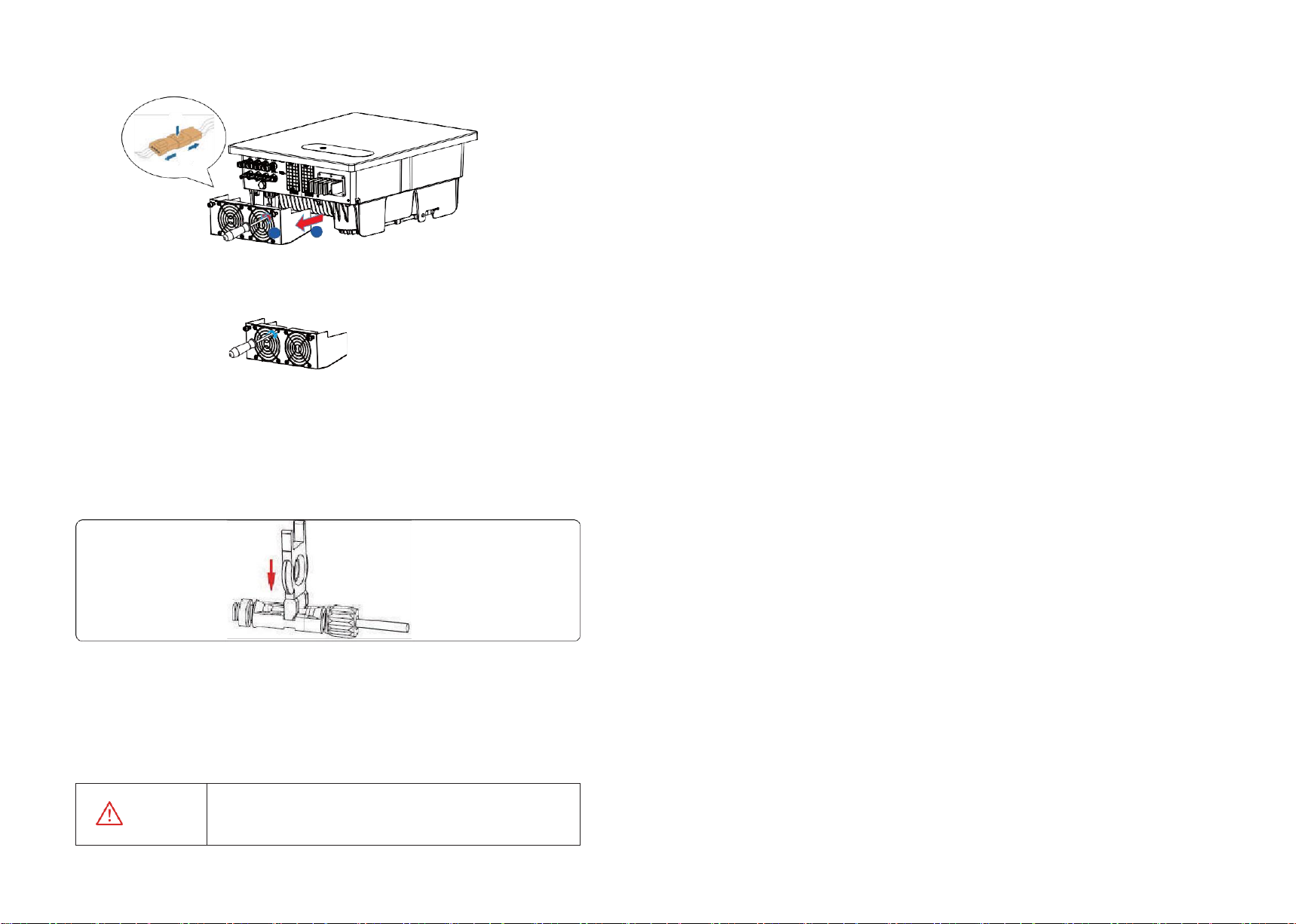
Fan Maintenance
Table 9-1.Maintenance checklist and interval
When the external fan of the inverter can’t work normally, the inverter may not cool effectively. It may affect
the efficiency of the inverter or cause derating operation. Keep the fan clean and replace the damaged fan in
time.
Step1 Shutdown the inverter.
Step2 Refer to electrical connection installation and disconnect the inverter in the opposite steps.
Step3 Refer to mechanical installation and remove the inverter in the opposite steps.
Step4 Screw down two security screws anticlockwise which on the inverter fan bracket .
C0-Internal power
supply abnormal
1.
Ifthe alarm occurs occasionally, the inverter can be automatically recovered and no action is required.
2.
If the alarm occurs repeatedly, the inverter cannot work properly. Please contact the customer service
center.
C2-Inverter over dc-
bias current
1.
Ifthe alarm occurs occasionally, the inverter can be automatically recovered and no action is required.
2.
Ifthe alarm occurs repeatedly, the inverter cannot work properly. Please contact the customer service
center.
C3-Inverter relay
abnormal
1.
Ifthe alarm occurs occasionally, the inverter can be automatically recovered and no action is required.
2.
If the alarm occurs repeatedly, the single-phase inverter, please check whether the live line and zero line of
the contact connection is reversed; the three-phase inverter check the live line to zero line and the voltage of
the live line to the ground. If the grid side is normal, please contact the customer service report repair.
C5-Inverter over
temperature
1.
If the alarm occurs occasionally, the inverter can be automatically restored, no action required.
2.
Ifthe alarm occurs repeatedly, pls. check the installation site for direct sunlight, good ventilation, and high
ambient temperature (Such as installed on the parapet). If the ambient temperature is lower than 45° C and
the heat dissipation is good, contact the customer service center.
C6-GFCI abnormal
1.
Ifthe alarm occurs occasionally, it could have been an occasional exception to the external wiring, the
inverter can be automatically recovered, no action required.
2.
If it occurs repeatedly or cannot be recovered for a long time, please contact customer service to
report repair.
C7-System type
error
Ifthe alarm occurs, the inverter can not work, pls. restart the inverter. If the alarm continues, please
contact customer service to report repair.
C8-Fan abnormal
1.
Ifthe alarm occurs occasionally, pls. restart the inverter.
2.
Ifit occurs repeatedly or cannot be recovered for a long time, check whether the external fan is blocked
by foreign objects. Otherwise, contact customer service.
C9-Unbalance Dc-
link voltage
1
、
If the alarm occurs occasionally, the inverter can be automatically recovered and no action is required.
2
、
If the alarm occurs repeatedly, the inverter cannot work properly. Please contact the customer
service center.
CA-Dc-link over
voltage
1
、
If the alarm occurs occasionally, the inverter can be automatically recovered and no action isrequired.
2
、
If the alarm occurs repeatedly, the inverter cannot work properly. Please contact the customer
service center.
CB-Internal
communication
error
1
、
If the alarm occurs occasionally, the inverter can be automatically recovered and no action is required.
2
、
If the alarm occurs repeatedly, the inverter cannot work properly. Please contact the customer
service center.
CC-Software
incompatibility
1
、
If the alarm occurs occasionally, the inverter can be automatically recovered and no action is required.
2
、
If the alarm occurs repeatedly, the inverter cannot work properly. Please contact the customer
service center.
CD-Internal storage
error
1
、
If the alarm occurs occasionally, the inverter can be automatically recovered and no action is required.
2
、
If the alarm occurs repeatedly, the inverter cannot work properly. Please contact the customer
service center.
CE-Data
inconsistency
1
、
If the alarm occurs occasionally, the inverter can be automatically recovered and no action is required.
2
、
If the alarm occurs repeatedly, the inverter cannot work properly. Please contact the customer
service center.
CF-Inverter
abnormal
1
、
If the alarm occurs occasionally, the inverter can be automatically recovered and no action isrequired.
2
、
If the alarm occurs repeatedly, the inverter cannot work properly. Please contact the customer
service center.
CG-Boost abnormal
1
、
If the alarm occurs occasionally, the inverter can be automatically recovered and no action is required.
2
、
If the alarm occurs repeatedly, the inverter cannot work properly. Please contact the customer service
center.
36
REV.1-Preliminary S.MG-OM:SG 5-30T
(Only take 25k model as an example)
Step5 Use a soft brush to clean the fan. If you need to replace the fan, use a screwdriver to unscrew
the fan bracket and remove the fan.
Step6 Install the new fan in the opposite steps, and then power on the system.
------Ending
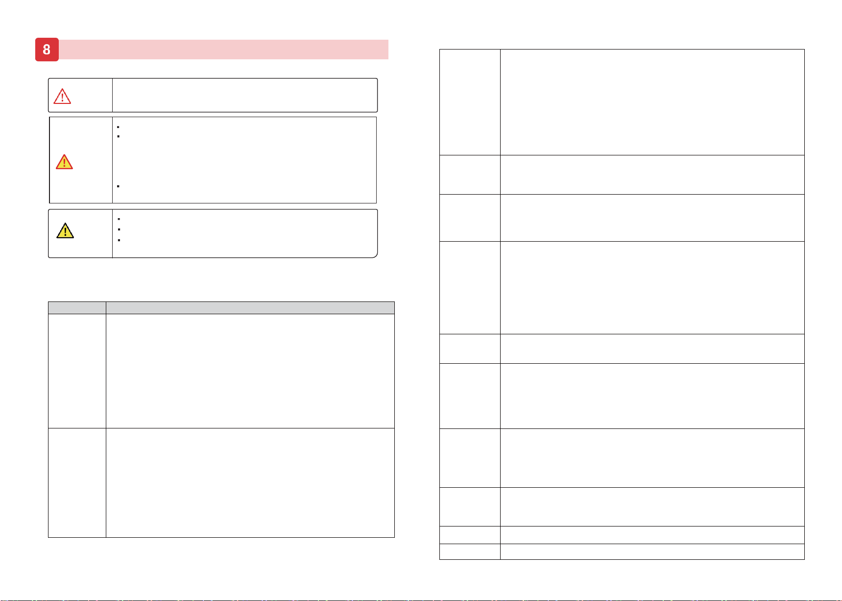
Inverter Uninstall
Inverter uninstall requires below procedure:
Step1: Disconnection all electric connections including these of communications
cables, DC input cables, AC output cables and the PGND cables.
Note:
Figure 9.1 Removing DC input connector
When uninstalling DC input connectors, insert removal wrench into the bayonet
shown in Figure, press the wrench down, and take out the connector.
Step2: Remove the inverter from its rear panel.
Step3: Remove the rear panel.
1
2
WARNING
Before uninstalling all electric connections, DC input connector, AC output
cables and the PGND cables, please ensure that both the AC terminal and
the DC terminal are powered off. And the DC switch is OFF to avert
equipment damage or personal injury.
36
REV.1-Preliminary S.MG-OM:SG 5-30T
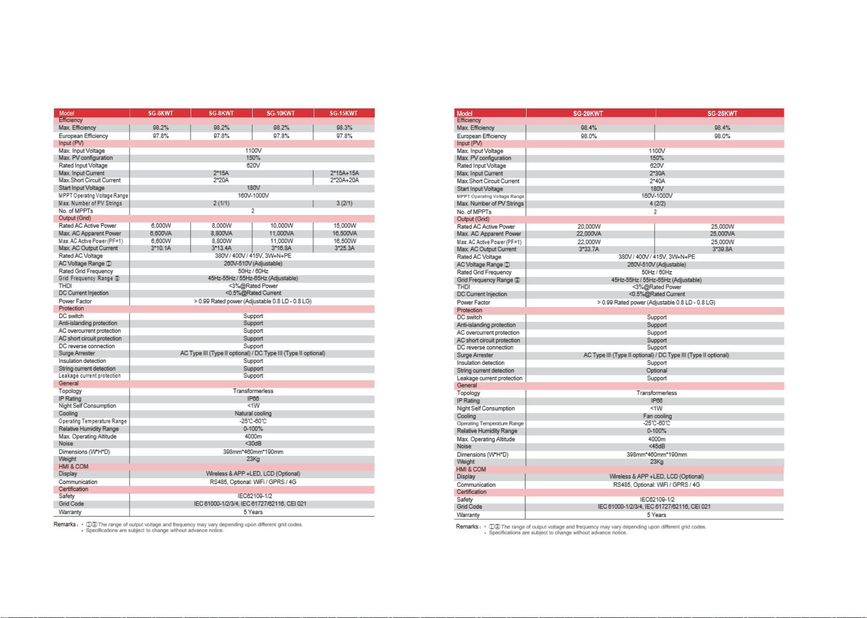
9.Technical Specifications

36
REV.1-Preliminary S.MG-OM:SG 5-30T
10 Technical assistance
SolarMG offers a technical assistance and consultancy service.
To take advantage of this service, the following number is active: 055911077,
Or by writing to the email: support@solarmg.it
This manual suits for next models
9
Table of contents
Other SOLARMG Inverter manuals


Popular Inverter manuals by other brands

Deye
Deye SUN-1K-G user manual

2 Save Energy
2 Save Energy Owl Intuition-PV Getting started

Mitsubishi Electric
Mitsubishi Electric F800-E Series instruction manual

Sierra wave
Sierra wave Solar Link 1000 operating instructions

SOLIS
SOLIS S6-GR1P6K Installation and operation manual

Enercell
Enercell 22-137 user guide


