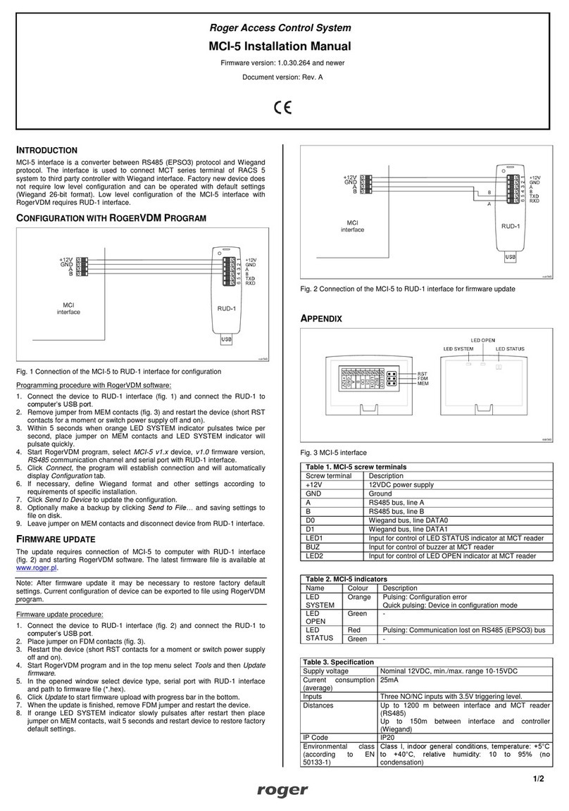
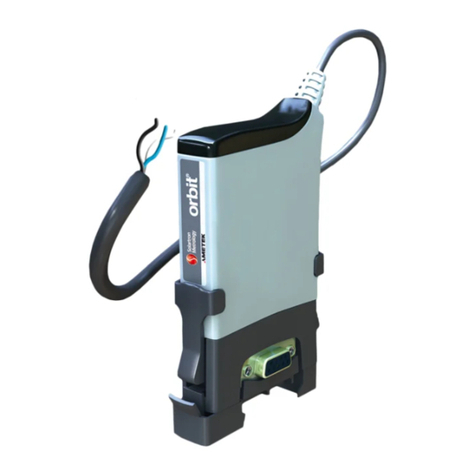
Solartron Metrology AMETEK ORBIT ACS SI100 User manual


1 GENERAL
1.1 DOCUMENTATION CROSS REFERENCE
503083 SI100 & SI200 Data Sheet
503174 SI400 Data Sheet
503094 Orb t®ACS and D g tal Probe and
L near Encoder User Leaflet
Deta l ng the spec f c requ rements for us ng the D g tal Probe or
L near Encoder (LE) such as mount ng deta ls
503145 Orb t LT Laser user leaflet Deta l ng the spec f c requ rements for us ng the Orb t LT laser such
as product handl ng & conf gurat on
503158 Orb t LTH Laser user leaflet Deta l ng the spec f c requ rements for us ng the Orb t LTH h gh
performance laser such as product handl ng & appl cat ons
502914 Orb t Module Manual Conta ns spec f c nformat on for the Analogue Input Module (AIM)
503113 SI100 & SI200 Qu ck Keypad Gu de
503116 Orb t ACS Modbus Parameter Map –
SI100/SI200
503166 Orb t ACS Modbus Parameter Map –
SI400
1.2 TRADEMARKS AND COPYRIGHTS
Informat on n th s document s subject to change w thout not ce.
No part of th s document may be reproduced or transm tted n any form or by means, electron c or mechan cal, for any purpose,
w thout the express perm ss on of Solartron Metrology.
© 2015 Solartron Metrology Ltd. All r ghts reserved. M crosoft®, W ndows®XP, W ndows®V sta, W ndows®7, W ndows®8,
W ndows®10, Excel®, VBA and VB are reg stered trademarks or trademarks of M crosoft Corporat on n the Un ted States and/or
other countr es.
503110 - Orb t ACS Manual Issue 9 2 of 63

Orb t® s a reg stered trademark of Solartron Metrology Ltd
1.3 CONTACT INFORMATION
For updated nformat on, troubleshoot ng gu de and to see our full range of products, v s t our webs te:
http://www.solartronmetrology.com
2 INTRODUCTION
Th s manual spec f cally caters for the Orb t ACS (Automat on and Control System) products, SI100 and SI200, as well as the SI400
product v a d fferences as spec f ed n sect on 20 (SI400 Append x).
2.1 SCOPE
The Orb t® ACS system prov des products spec f cally des gned to create small l near measurement systems w th s mple PLC
nterfac ng or products wh ch can be stand-alone readouts. Each module conta ns an ntegral LCD d splay and keypad for sett ng up
and v sual d splay of measurements. Bas c Input output s prov ded by d screte l nes or a ser al nterface conf gured n var ous ASCII
formats or Modbus RTU over RS485 or RS232. For larger measurement systems, Solartron's Orb t D g tal Measurement System
wh ch s a PC based system may be a more flex ble solut on.
The Orb t ACS system compr ses three ma n types: the SI100, SI200 and SI400. These products are def ned n the relevant data
sheets.
2.2 NAVIGATE THIS DOCUMENT
Hyperl nks are ncluded to a d nav gat on.
To return to the po nt where you have jumped from, most pdf readers have a ‘Prev ous Page V ew’ button,
alternat vely use the keyboard shortcut 'ALT' + left arrow key.
503110 - Orb t ACS Manual Issue 9 3 of 63

3 SAFETY SUMMARY
WARNING statements dent fy cond t ons or
pract ces that could result n personal njury
or loss of l fe.
CAUTION statements dent fy cond t ons or
pract ces that could result n damage to the
equ pment or other property
Symbols in this m nu l
Ind cates caut onary or other
nformat on
W rnings nd C utions
W rning: Do not operate n an explos ve atmosphere.
W rning: th s equ pment s not ntended for safety cr t cal appl cat ons
W rning: do not exceed max mum rat ngs as spec f ed n th s document under
nd v dual modules.
C ution: Low Volt ge
Th s equ pment operates below the SELV and s therefore outs de the scope of the
Low Voltage D rect ve
Service nd Rep ir
CAUTION: Th s equ pment conta ns no user serv ceable parts. Return to
suppl er for all serv ce and repa r
All of the Products are CE marked and comply w th EN61000-6-3 Electr cal Em ss ons and EN61000-6-2 Electr cal Immun ty and
EN61326-1.
503110 - Orb t ACS Manual Issue 9 4 of 63

4 TABLE OF CONTENTS
1 GENERAL.....................................................................................................................................................................................................2
1.1 DOCUMENTATION CROSS REFERENCE..............................................................................................................................................2
1.2 TRADEMARKS AND COPYRIGHTS........................................................................................................................................................2
1.3 CONTACT INFORMATION........................................................................................................................................................................3
2 INTRODUCTION...........................................................................................................................................................................................3
2.1 SCOPE.......................................................................................................................................................................................................3
2.2 NAVIGATE THIS DOCUMENT..................................................................................................................................................................3
3 SAFETY SUMMARY.....................................................................................................................................................................................4
4 TABLE OF CONTENTS................................................................................................................................................................................5
5 GLOSSARY OF TERMS AND BASIC SYSTEM INFORMATION...............................................................................................................9
5.1 TERMS ASSOCIATED WITH THE ORBIT ACS HARDWARE................................................................................................................9
6 MECHANICAL INSTALLATION.................................................................................................................................................................10
7 ELECTRICAL INSTALLATION..................................................................................................................................................................11
7.1 PC System Requirements......................................................................................................................................................................11
7.1.1 PC Hardware Requirements....................................................................................................................................................................................................................................11
503110 - Orb t ACS Manual Issue 9 5 of 63

7.1.2 PC Software Requirements......................................................................................................................................................................................................................................11
7.2 Inst lling the Orbit3 Support P ck for Windows® softw re..............................................................................................................11
7.3 Connections............................................................................................................................................................................................12
7.4 GROUNDING, CABLES AND POWER SUPPLIES................................................................................................................................13
7.5 Noisy Electric l Environments..............................................................................................................................................................14
7.5.1 Residential, Commercial and Light ndustrial Environments.................................................................................................................................................................................14
7.5.2 ndustrial Environments..........................................................................................................................................................................................................................................14
8 CONFIGURATOR APPLICATION..............................................................................................................................................................14
9 FUNCTIONS AND DISPLAYS....................................................................................................................................................................16
9.1 SI100 nd SI200 DISPLAYS...................................................................................................................................................................17
9.2 SI100 nd SI200 ACTIONS.....................................................................................................................................................................18
9.3 MENU SCREENS.....................................................................................................................................................................................22
9.3.1 Top Level Menu......................................................................................................................................................................................................................................................23
9.3.2 Configure Probe(s)..................................................................................................................................................................................................................................................24
9.3.3 Probe Sub-menus.....................................................................................................................................................................................................................................................25
9.3.4 Measure Menu.........................................................................................................................................................................................................................................................27
9.3.5 Peak, Preset, Limits and Misc Menu.......................................................................................................................................................................................................................29
9.3.6 Output, nput and Communications Menu..............................................................................................................................................................................................................30
9.4 COMMON ERROR MESSAGES & STATUS CODES............................................................................................................................31
9.4.1 Display Error messages...........................................................................................................................................................................................................................................31
9.4.2 Detachable Probes Error Messages.........................................................................................................................................................................................................................31
9.4.3 Modbus Errors.........................................................................................................................................................................................................................................................32
10 SECURITY LEVELS..................................................................................................................................................................................33
503110 - Orb t ACS Manual Issue 9 6 of 63

11 OUTPUTS..................................................................................................................................................................................................34
12 DIGITAL INPUTS......................................................................................................................................................................................35
12.1.1 Digital nputs Configuration Options....................................................................................................................................................................................................................35
12.1.2 Discrete Print nput................................................................................................................................................................................................................................................36
13 TIMING AND MEASUREMENT INFORMATION.....................................................................................................................................38
14 SERIAL COMMUNICATIONS (GENERAL).............................................................................................................................................39
14.1 RS232 nd RS485 sign l levels...........................................................................................................................................................39
14.2 TYPICAL RS232 WIRING......................................................................................................................................................................40
15 ASCII BASED SERIAL COMMUNICATIONS PROTOCOL.....................................................................................................................41
15.1 Orbit ACS Seri l Communic tions Protocol......................................................................................................................................41
15.2 SI3500 Comp tibility Protocol............................................................................................................................................................44
15.3 SI1500 Comp tibility Protocol............................................................................................................................................................45
15.4 C55 Comp tibility Protocol.................................................................................................................................................................46
15.5 ASCII Ch r cter Set..............................................................................................................................................................................47
16 MODBUS BASED SERIAL COMMUNICATIONS PROTOCOL..............................................................................................................48
16.1 INTRODUCTION....................................................................................................................................................................................48
16.2 OVERVIEW OF MODBUS COMMUNICATIONS..................................................................................................................................48
16.2.1 Modbus Master/Slave............................................................................................................................................................................................................................................48
16.2.2 Modbus Unit D.....................................................................................................................................................................................................................................................49
16.2.3 Parameters.............................................................................................................................................................................................................................................................49
503110 - Orb t ACS Manual Issue 9 7 of 63

16.2.4 Master Command Messages..................................................................................................................................................................................................................................50
16.2.5 Slave Unit Responses............................................................................................................................................................................................................................................51
16.2.6 Modbus Function Codes Supported by S Products..............................................................................................................................................................................................52
16.2.7 Parameter Types....................................................................................................................................................................................................................................................53
16.2.8 Parameter Map......................................................................................................................................................................................................................................................54
16.2.9 ACS, Modbus Floating point ................................................................................................................................................................................................................................54
17 MEASUREMENT RESOLUTION, AVERAGING AND BANDWIDTH....................................................................................................55
18 MISCELLANEOUS....................................................................................................................................................................................56
18.1 FIRMWARE UPGRADES.......................................................................................................................................................................56
19 RETURN OF GOODS...............................................................................................................................................................................57
20 SI400 APPENDIX......................................................................................................................................................................................58
20.1 SI400 Summ ry.....................................................................................................................................................................................58
20.2 Section 9.1 - SI100 nd SI200 DISPLAYS...........................................................................................................................................58
20.2.1 Screen 1 & 2..........................................................................................................................................................................................................................................................58
20.2.2 Screen 3.................................................................................................................................................................................................................................................................59
20.3 Section 9.2 - SI100 nd SI200 ACTIONS.............................................................................................................................................60
20.4 SECTION 9.3 - MENU SCREENS.........................................................................................................................................................61
20.5 SECTIONS 11 - OUTPUTS & 12 - DIGITAL INPUTS...........................................................................................................................61
20.6 SECTION 15.1 - Orbit ACS Seri l Communic tions Protocol..........................................................................................................62
21 REVISION HISTORY.................................................................................................................................................................................63
503110 - Orb t ACS Manual Issue 9 8 of 63
5 GLOSSARY OF TERMS AND BASIC SYSTEM INFORMATION
5.1 TERMS ASSOCIATED WITH THE ORBIT ACS HARDWARE
SI Ser es
The SI Ser es refers to all of the SI100, SI200 and SI400 products.
D splay
The L qu d Crystal D splay on the top of the SI Ser es modules prov d ng d splayed nformat on
Keypad
The f ve way keypad on the top of the SI Ser es allow ng funct onal and menu nav gat on
D screte Inputs
L nes nto the SI Ser es that allow remote control of certa n parameters
D screte Outputs
L nes out of the SI Ser es that can be used to dr ve external loads. These can be set e ther as NPN or PNP conf gurat on
Ser al Interface
E ther ASCII protocols (as def ned n th s manual) or Modbus RTU or Modbus ASCII. The ser al bus can be conf gured as e ther
RS232 or RS485 s gnal levels.
D g tal Probe
A standard Solartron product that can be connected to the SI200 to form a two channel measurement dev ce, or to the SI400 to
make up to a four channel dev ce.
503110 - Orb t ACS Manual Issue 9 9 of 63

Connect on Un t
SI100: Base Module to allow the un t to be mounted on a DIN ra l or screwed down to a mount ng plate
SI200: A 3 way connector housed n a case on the base of the SI200, wh ch allows a D g tal probe to be connected to form a two
channel product
SI400: A 3 way connector housed n a case on the base of the SI400, wh ch allows three D g tal probes to be connected to form a
four channel product
6 MECHANICAL INSTALLATION
The SI Ser es products are not a sealed nstrument and care should be taken when nstall ng the nstrument n env ronments where
contam nat on can come nto contact w th the un t.
It s adv sable to protect the un t and f regular access to the keypad s requ red use a remote sw tch connected to the d screte nputs
to perform the requ red user act on.
503110 - Orb t ACS Manual Issue 9 10 of 63

7 ELECTRICAL INSTALLATION
Note. The Orb t ACS Ser es of products are not sealed nstruments and care should be taken when nstall ng n env ronments where
contam nat on can come nto contact w th the un t.
7.1 PC SYSTEM REQUIREMENTS
7.1.1 PC H rdw re Requirements
•Personal computer w th a processor runn ng at 1GHz or faster w th 2GB or more RAM.
•An ava lable USB port.
7.1.2 PC Softw re Requirements
•M crosoft W ndows® operat ng system (W ndows® XP, or later)
•Solartron Orb t3 Support Pack For W ndows.
7.2 INSTALLING THE ORBIT3 SUPPORT PACK FOR WINDOWS® SOFTWARE
Important! Please ensure that you have Adm n strat ve access r ghts for nstall ng th s software.
Before you can use the Orb t ACS conf gurator utl ty, you must have the Orb t3 Support Pack for W ndows® software nstalled on your
computer; th s s freely ava lable from the Solartron webs te (http://www.solartronmetrology.com).
Th s w ll nstall the latest vers on of th s manual, the Orb t ACS conf gurator utl ty and Orb t3 Updater that are requ red for us ng Orb t ACS
products.
503110 - Orb t ACS Manual Issue 9 11 of 63

7.3 CONNECTIONS
NB. For RS232 connect on, the 0V connect on must be connected to the RS232 GND
DO NOT CONNECT ANY POWER SOURCES TO THE 9 WAY D DYPE OF THE SI200/SI400
503110 - Orb t ACS Manual Issue 9 12 of 63
Th s sect on descr bes how to connect the un t

7.4 GROUNDING, CABLES AND POWER SUPPLIES
It s adv sable to prov de a good ground po nt for the SI Ser es.
The SI100 s a standalone un t, normally the probe would be connected to ground, there s no spec f c need to ground the electron cs
module.
The SI200/SI400 can be connected to a Solartron D g tal
Probe us ng the n ne way connector, f both the SI200/SI400
and the D g tal Probe(s) are mounted on a DIN ra l add t onal
ground ng can be performed us ng the ground ng bracket
(see d agram)
The d g tal probe has two nd cat on LEDS. The blue led s on
when the SI200/SI400 and d g tal probe(s) are
commun cat ng. The red led w ll flash f there s not enough
power reach ng t. Th s may nd cate a fault w th the
SI200/SI400.
If the un t s the f rst or last dev ce n a mult -drop RS485
network, to meet the term nat on requ rements we
recommend the f tt ng of a 120 res stor across p ns 3 and 4
of the 12 way connector.
503110 - Orb t ACS Manual Issue 9 13 of 63

7.5 NOISY ELECTRICAL ENVIRONMENTS
Th s sect on d scusses the type of nstallat on requ red depend ng on the electr cal env ronment.
7.5.1 Res dent al, Commerc al and L ght Industr al Env ronments
Typ cally, th s w ll be an off ce, laboratory or ndustr al env ronment where there s no equ pment l kely to produce h gh levels of
electr cal nterference, such as welders or mach ne tools.
Connect ons may be made us ng tw sted, unscreened w re. Th s s a cost effect ve opt on and w ll g ve good performance n th s
env ronment.
Standard equ pment w re such as 7/0.2 (24 AWG) can be tw sted together as requ red. Standard data cable such as gener c CAT5
UTP w ll also g ve good performance.
7.5.2 Industr al Env ronments
Typ cally, th s w ll be an ndustr al env ronment where there s equ pment l kely to produce h gh levels of electr cal nterference, such
as welders, mach ne tools, cutt ng and stamp ng mach nes.
Connect ons should be made us ng screened cable. Bra ded or fo l screened cables may be used. The cable screen should be
connected to the Orb t ACS un t at the 0V connect on.
In some part cularly no sy env ronments t may be necessary to add ferr te f lter components on power and/or data cables.
When select ng the type of w re or cable to be used, cons der the follow ng parameters:
Screen ng.• Conductor s ze (res stance).Mechan cal aspects such as flex b l ty and robustness.
Th s s not a complete l st. Installat ons may requ re other spec al cable character st cs.
8 CONFIGURATOR APPLICATION
For easy setup of mult ple Orb t ACS un ts, the Orb t ACS conf gurator utl l ty for W ndows based PCs s ava lable, ncluded w th the
Orb t3 Support Pack for W ndows.
The un t must be connected to the PC v a the USB M n B port on the rear of the un t and then powered n the normal way, as t s not
powered v a the USB lead.
503110 - Orb t ACS Manual Issue 9 14 of 63

The conf gurator m m cs the sett ngs ava lable on the un t tself and enables the user to save a un t's conf gurat on and then load the
same conf gurat on onto other un ts.
The conf gurator has mult ple 'tabs' (see below). Each w ll d splay and allow adjustment of the r respect ve sett ngs.
503110 - Orb t ACS Manual Issue 9 15 of 63

9.1 SI100 AND SI200 DISPLAYS
503110 - Orb t ACS Manual Issue 9 17 of 63

9.2 SI100 AND SI200 ACTIONS
The SI100 and SI200 can perform act ons e ther v a the keypad or the 4 d screte nputs
The Act ons are descr bed n the follow ng table
503110 - Orb t ACS Manual Issue 9 18 of 63

ACTION DESCRIPTION COMMENT SI100 SI200
Pr Track Sets the Pr mary Channel nto TRACK type
measurement
The d splay follows the probe movement n both d rect ons ☻ ☻
Pr Peak+ Sets the Pr mary Channel nto PEAK+ type.
measurement
The d splay shows the most pos t ve value ☻ ☻
Pr Peak- Sets the Pr mary Channel nto PEAK- type
measurement.
The d splay shows the most negat ve value ☻ ☻
Pr PKRST RESETS the Pr mary Channel to the current
probe read ng when n PEAK+ or PEAK- type
measurement.
The d splay shows the current probe read ng mmed ately follow ng the
Pr PKRST act on and then operates as e ther PEAK+ or PEAK-
depend ng on wh ch measurement type s set.
☻ ☻
Pr ABS Sets the Pr mary Channel to ABSOLUTE
Mode d rectly d splays the probe
measurement. (no zero or offset)
☻ ☻
Pr ZERO Sets the Pr mary Channel to ZERO Mode
d rectly d splays the probe measurement.
The d splay and value of the ser al output s set to ZERO. All further
measurements are w th respect to th s new zero.
(Example: If the measur ng range s 0 to 10mm and the absolute read ng
s 4mm, on Pr ZERO act on the d splay and value of the ser al output w ll
be zero. Then f the probe s moved to t to an absolute pos t on of 6mm
the d splay and ser al output w ll nd cate +2mm)
☻ ☻
Pr Preset Sets the Pr mary Channel on SI200 to
PRESET Mode d rectly d splays the probe
measurement.
The d splay and value of the ser al output s set to the PRESET VALUE
for Pr mary Channel. All further measurements are w th respect to th s
new value.
(Example: If the measur ng range s 0 to 10m, the absolute read ng s
4mm,and the Pr mary Channel Preset s 20 then follow ng a Pr PRESET
act on the d splay and value of the ser al output w ll be 20mm. Then f the
probe s moved to t to an absolute pos t on of 6mm the d splay and ser al
output w ll nd cate +22mm)
☻ ☻
PAMxRST If the Pr mary d splay s MaxA-M nA resets
the Max mum A value to zero
☻ ☻
PAMnRST If the Pr mary d splay s MaxA-M nA resets
the M n mum A value to 0
☻ ☻
503110 - Orb t ACS Manual Issue 9 19 of 63

PMxMnRST If the Pr mary d splay s MaxA-M nA resets
th s value to zero or the PRESET value
☻ ☻
PRINT Sends the measurement and other data out
v a the ser al commun cat ons l nk
Note the ser al commun cat ons must be set to match the rece v ng
dev ce
☻ ☻
PBMxRST If the Pr mary d splay s MaxB-M nB resets
the Max mum B value to zero
☻ ☻
PBMnRST If the Pr mary d splay s MaxB-M nB resets
the M n mum A value to 0
☻ ☻
PMxMnRST If the Pr mary d splay s MaxB-M nB resets
th s value to zero or the PRESET value
☻ ☻
SecTrack Sets the Secondary Channel on SI200 nto
TRACK type measurement
The d splay follows the probe movement n both d rect ons ☻ ☻
SecPeak+ Sets the Secondary Channel on SI200 nto
PEAK+ type. measurement
The d splay shows the most pos t ve value ☻ ☻
SecPeak- Sets the Secondary Channel on SI200 nto
PEAK- mode
The d splay shows the most negat ve value ☻
SecPKRST RESETS the Secondary Channel to the
current probe read ng when n PEAK+ or
PEAK- type measurement.
The d splay shows the current probe read ng mmed ately follow ng the
PKRST act on and then operates as e ther PEAK+ or PEAK- depend ng
on wh ch measurement type s set.
☻
SecABS Sets the Secondary Channel on SI200 to
ABSOLUTE Mode d rectly d splays the probe
measurement. (no zero or offset)
See Pr ABS ☻
SecZERO Sets the Secondary Channel on SI200 to
ZERO Mode d rectly d splays the probe
measurement.
See Pr ZERO ☻
SecPreset Sets the Secondary Channel on SI200 to
PRESET Mode d rectly d splays the probe
measurement.
See Pr PRESET
(note the Pr mary and Secondary Preset values can be d fferent
☻
SAMxRST If the Secondary d splay s MaxA-M nA resets
the Max mum A value to zero
☻
SAMnRST If the Secondary d splay s MaxA-M nA resets
the M n mum A value to 0
☻
503110 - Orb t ACS Manual Issue 9 20 of 63
This manual suits for next models
4
Table of contents
Other Solartron Metrology Control System manuals