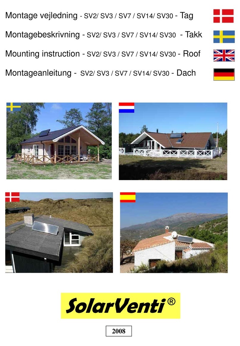
SolarVenti SV3 User guide

Montage vejledning - SV2 / SV3 / SV7 / SV14 / SV30 - Tag
Montážní instrukce -
SV2 / SV3 / SV7 / SV14 - na střechu
Mounting instruction - SV2 / SV3 / SV7 / SV14/ SV30 - Roof
Montageanleitung - SV2 / SV3 / SV7 / SV14 / SV30 - Dach
Okt 2009

2
A
3
B
4
5
B
C
6
A
Type 1 Installationsforslag til tegl- eller eternittag mv. (Tal i parentes gælder for SV2 og SV3)
Stativet samles i en vinkel, der gør, at den samlede hældning bliver på min. 600
De medfølgende trykfordelere (H) sættes mellem tagplade og stativ. Stativet
sættes oven på bølgetoppe og der skal bore hul i både stativfod og tagplade
- ud for lægter eller evt. spær. Stativet spændes forsigtigt fast
Til tagmontage sættet hører et stykke 160 (125) mm
fleksibelt plastrør, som trækkes uden på det 125 (100)
mm aluflexrør. Dette af hensyn til isolering og beskyttel-
se af selve luftrøret.
Strimler af selvklæbende isolering sættes om det 125
(100) mm flexrør ved enderne inden det større flexrør
trækkes udenpå og fastgøres.
Find det sted mod syd hvor solfangeren skal sidde. Ved tegltag fjernes en teglsten. Til eternit kan hullet laves ved at bore mange mindre
huller ved siden af hinanden. Benyt evt. en stiksav eller 140 mm kopbor.
Lav en lille prøveopstilling, så det bedst muligt kommer til at passe med hul og stativplacering. Solfangeren sidder vandret, men kan
som vist på billedet godt følge et tags hældning "den anden vej", hvis det er bedst i forhold til syd.
Eternitplade løsnes så taggennem-
føring kan komme ind under.
Den metalforstærkede gummiplade (Perform) bankes forsigtigt
ind til tagpladen, brug en gummihammer (Ikke metalhammer)
Et lille ombuk forneden på taggennemføringen stabiliserer
formen yderligere.
2
1
Hul bores
gennem tag
3
4 5
Perform gennemføring
A tag
B
Stativ 2 stk.
SV30 3 stk.
C
6
H
Trykfordelere
H

Typ 1 Instalační návod pro střechy s taškami nebo vlnitým eternitem (Čísla v závorce platí pro SV2 a SV3)
Stativ se složí tak, aby úhel sklonu pro panel byl min. 60°. Přibalené pružné
podložky (H) se umístí mezi střešní krytinu a stativ. Stativ se umístí na vrch vlnky a
provrtá se díra skrz stativ i tašku. Díry musí být nad latěmi nebo event. trámy. Stativ
se opatrněpřipevní.
K montážní saděna střechu náleží i šedivý flexibilní
plastový kryt 160 (125) mm, který se přeháhne přes
hliníkovou flexibilní rouru 125 (100) mm. Slouží k izolaci
hliníkové roury.
Proužky samolepící těsnící izolace se nalepí přímo na
hliníkovou trubku 125 (100) mm na obou koncích dřív
než se nasadí šedivý izolační kryt.
Najděte nejvýhodnější umístění, co nejvíce na jih. Vyzkoušejte, kde bude stativ optimálněumístěn a kde bude potřeba udělat průchod
pro flexibilní rouru. U střech s taškami se jedna taška vyndá. U vlnité eternitové střechy se může vyvrtat několik malých děr vedle sebe.
K dokončení se pak dá použít přímočará pilka či vrtačka s korunkou 140 (115) mm.
Solární panel lze umístit vodorovněnebo svisle (podél sklonu střechy - to v případě, že by byl lépe orientovaný na jih, viz. obrázek 5.
Taška nad taškou, ve které bude prostup
se dole uvolní, aby se průchodka dostala
pod její okraj.
Černá průchodka (Perform) se přiloží na tašku, aby díry
pasovaly a lehce se přiklepe gumovou palicí, tak aby dostala
pořebný tvar a dole se trochu dala přehnout přes okraj tašky.
Tím bude její forma stabilizována ještěvíc.
2
1
Provrtá se díra
skrz střechu
3
4 5
Perform průchodka
A
Střecha
B Stativ 2 ks.
U SV30 3ks.
C
6
Type 1 Installation suggestions for asbestos roofs, tile roofs etc. (Text with this red color are for SV2 andSV3)
The rack is positioned at an angle that makes the total tilt at least 600 . The
included rack-arms (H) are placed between roof plates and rack. The rack is
installed on wave tops, and holes must be drilled through rack foot as well as
roof platesinto laths or rafters. The rack is carefully tightened to roof with the
delivered screws.
With the roof installation kit comes a piece of 160 mm fle-
xible plasttube which must be mounted around the 125 mm
alu flextube. This must be made for insulation and protec-
tion purposes. Stripes of self-adhesive insulation are fixed
at the ends of the 125 mm flextube, before the larger flextu-
be is mounted around it.and fixed. PS: If a rack is not used,
the 160 mm tube can be omitted
Find the best place for the air collector and mark the hole 140 (120) mm. If tile, remove one of these. If asbestos, make a hole by dril-
ling a lot a smaller holes next to each other. If necessary, use a compass saw.
Make a small test-arrangement that secures the best position for hole and position of rack. The air collector is horizontal but it can, as
shown in picture, follow the tilt of a roof ”the other way” if this is better in order to face the sun.
Asbestos plate is loosened, so that
the lead-in can be placed under it.
The metal-reinforced rubber lead-in (Perform) is carefully
tapped onto the roof plate. Use a rubber hammer, (not a
steel hammer). A small backfold at the lower part of the lead-in
will further stabilize the form.
2
1
A hole is drilled
through the roof
3
4 5
Perform rubber let-in
A
roof
B Rack:
2 pcs.
SV30:
3 pcs.
C
6
Type 1 Installationsvorschlag für Well-, Pfannen– und Eternitdach mit Überlappung. (Text mit rot ist für SV2-SV3)
Das Gestell wird so montiert dass der Neigungswinkel mindestens 60° beträgt. Die
Kunststoff Druckverteiler (H) werden zwischen Dach und Gestell gelegt.
Das Gestell sitzt oben auf den Dachwellen. Markieren Sie die dann die Lage der
Dachlatten auf dem Gestell (Unterteil) und bohren sie an diesen Stellen die Löcher
für die Schrauben.
Danach das Gestell vorsichtig festschrauben. (Löcher vorbohren über die Latten)
Durch die Montage des Kollektors wird das Gestell stabilisiert
Als Isolierung und Schutz von der 125 mm (100
mm) alu - Flexrohr benutzen Sie das 160 mm
(125 mm) Flexrohr. Oben und unter können Sie
Isolierstreifen festkleben als Dichtung.
Suchen sie die richtige Stelle, wo der Kollektor sitzen muss und markieren sie das Loch für die Dachdurchführung
(Größe: siehe Rückseite). Beim Ziegeldach entfernen sie einen Ziegel.
Stellen sie das Gestell probeweise auf, so dass das Gestell und das Loch zur Dachdurchführung zueinander passen.
Der Kollektor kann willkürlich gedreht werden.
Dachplatte oder Ziegel anheben und
den Perform satz darunter schieben.
Die Performplatte wird geformt evt. mit einem Gummihammer
(kein Metalhammer!) Wenn man die untere erste centimeter
umbiegt, versterkt man die Form.
2
1
Loch wird gebohrt
durch das Dach
3
4 5
Perform DachdurchführungA
Dach
B Gestell :
2 Stück
SV30:
3 Stück
C
6
Druckverteiler
H
rack-arms
H
H Pružné podložky

tag
SolarVenti
7
D
E F
8
9
10
Mere information på: www.solarventi.dk
Hullet bores i loft 133-135 (115-120) mm.
Flexslange trækkes fra solfanger til studs på taggennemfø-
ring og aluflexrør trækkes videre under taget ned til loftsbe-
klædning. Alu-flexrør låser automatisk fast på studse med
gummilæber og kan
Montage af ledning til Afbryder eller Reguleringsenheden:
Læs standard vejledning som følger med din SolarVenti.
Når de flexslangerne er fastgjort kan man fæstne inddæk-
ningen yderligere ved at sætte (medfølgende) skruer med
gummiskiver i ved bølgetoppe. Tryk inddækningen godt ned
i bølgedale, inden skruen sættes i.
Ret til ændringer forbeholdes. SolarVenti er
uden ansvar for den endelige installation
Hvid dyse trykkes op og
drejes med uret. Kun 12 Volt
7
D
Aluflexrør bukkes let om nederst, så det
ikke glider op igen.
Kontraspjæld F sættes op i røret nedefra.
Ventilramme sættes op i aluflexrør og
skrues fast
8
Aluflexrør
E
9
10
Kontraventil
F
Type 1
H
Trykfordelere
H
Dobbelt
flexrør

Více informací na: www.solarventi.cz
Flexibilní trubka a šedivý kryt se natáhnou od panelu k průchodce,
další část se pak natáhne od ukončení průchodky pod střechou
k otvoru u stopu, zkrz díru až ke stropu uvnitřmístnosti. U panelu i
u průchodky se roura upevní dostatečnědíky černým gumovým
těsnícím kroužkům.
Zapojení drátkůdo vypínače či regulátoru: Přečtěte si
přibalené standardní montážní instrukce k SolarVenti.
Po připevnění flexibilních rour se dokončí připevňování
průchodky pomocí přibalených šroubkůs gumovou podložkou
na vrch vlnky. Důkladněpřitlačte průchodku do všech
prohlubní dřív, než nýty umístíte.
Právo na změny vyhrazeno. Solarventi
nenese zodpovědnost za konečnou instalaci.
Vstupní vzduchová krytka se
přiloží a lehce přitiskne ke
kovovému límci a otočí se po
směru hodinových ručiček. Pouze 12 Voltů!
7
Dvojitá
flexibilní
roura
D
Zpětná záklapka se prostrčí od stopu asi 10 cm do
flexibilní roury. Díra musí být 133 -135 mm (115-120)
8
Hliníková
flexibilní
roura
E
9 10
Zpětná
záklapka
F
Subject to alterations. SolarVenti disclaims
any responsibility for the final installation
More information on: www.solarventi.com
The hole is drilled 133-135 (115-120) mm through the ceiling.
A short aluflex tube is pulled from air collector to connection piece
on the lead-in, and an extra (long) aluflex tube is pulled under the
roof down through the hole in the ceiling.
Wire connection for the Switch or Regulator unit:
Read the standard installation guide for SolarVenti
When the flextubes have been installed, the rubber cover can be
further fastened with screws with rubber washers (into wave tops).
Press the cover properly down into roof surface before applying
screws.
White nozzle Is pressed
upwards and turned
clockwise. 12 Volts Only !
7
D
Bow the aluflextube slightly under the ceiling so it
cant slip back again.
The counter valve is mounted in the tube (prevents
airflow backwords)
The frame for the inlet nozzel is to be mounted. .
8
Aluflex tube
E
9
10
Counter valve
F
Mehr Information: www.solarventi.de
Das Loch durch die Decke muss 133-135 (115-120) mm. sein
Das flexible Alu-Rohr führt vom SolarVenti durch die Stutze
an der Dachdurchführung, und weiter vom Dach herunter zur
Decke. .
Das Alu-Flexrohr wird automatisch festgehalten von den
Gummilippen.
Montage von Kabel an Schalter oder Regulierungs-Einheit
Lesen Sie bitte die Standard Anleitung für Wandmontage
Hier sehen sie die Montage auf einem Welldach. Nachdem
beide flexiblen Schläuche befestigt sind, kann mithilfe von
zwei Schrauben die Dachdurchführung zusätzlich befestigt
werden.
Die Schrauben (mit Gummidichtung) werden auf dem Wel-
lenberg reingeschraubt..
Nach dem Festschrauben des Einbaurahmens
an der Decke kann man das Zuluftventil rein-
pressen und in Uhrzeigerrichtung festdrehen.
Nur 12 Volt !
7 Die Aluflexrohr wird leicht gebogen dass es sich
nicht zurückzieht.
Die Rückschlagklappe Fwird in das Rohr gesetzt.
Ventil-Einbaurahmen wird festgeschraubt.
8
9
10
125 mm Alurohr
und 160 mm
Kunststoff Flexrohr
D
Aluflexrohr
E Rückschlag-
klappe
F
Technische Änderungen und Irrtümer vorbehalten. Die Anleitung ersetzt keine
Installationsvorschriften. Der Hersteller / Lieferant übernimmt keine Gewähr
Typ 1
Type 1
Type 1
H Pružné podložky
rack-arms
H
Druckverteiler
H
2 x
Flex tube

Perform
A
3
B
12
14
Forslag til ledningsgennemføring
- KUN på tag med fald / hældning
over 10 grader.
Bor et hul til ledning og før denne
ned mellem alurør og ydre
plastrør
Ret til ændringer forbeholdes. SolarVenti er
uden ansvar for den endelige installation
Type 2 Installationsforslag til tagpaptag eller stålpladetag mv. Taghældning mindst 5 grader. Er taghældningen
mindre, bør man rådføre sig med en tagspecialist, evt. lade ham fortage denne del af montagen.
Installationen er nøjagtig som type 1 (læs denne) undtagen punkt 4. Dette punkt erstattes
nedenfor af punkt 12. Desuden medfølger der en ledningsgennemføring (d).
11
Når man er sikker på placeringen, og har lavet hullet, smører man flere striber
med tættemasse på pladen - også der hvor hullerne til skruer er.
Forinden kan man sætte aluflexrøret på. Så man er sikker på at det sidder kor-
rekt og at det uhindret kan trækkes gennem hullet.
Medfølgende skruer sættes rundt i kanten af gennemføringen.
Den metalforstærkede gummiplade (Perform) bankes forsigtigt ind til tagpladen,
brug en gummihammer (Ikke metalhammer)
Den medfølgende tætningsmasse smøres også på mellem tagpap og stativ.
Vigtigt: Overskud af tætningsmasse bør træde frem ved kanterne ogskruer skal
kun spændes let efter. Ellers deformeres materialet, som skrues i. Perform gennemføring
A
tag
B
14
12a
12

When the correct place has been found and the hole has been made, several
stripes of sealing compound are applied to the plate, also where the screw holes are.
Before that, the aluflextube should be installed so that you are sure that it is placed
correctly and can be easily pulled through the hole.
Screws (included) are fastened to all holes.
Note: screws must be carefully tighted - otherwise, the material which is screwed
in can deform.
A surplus of sealing compound should be visible along the edges.
Subject to alterations. SolarVenti disclaims
any responsibility for the final installation
Wire ducting - ONLY on roof
with fall / angle above 10°.
Make a hole for the wire as
shown, and draw the wire
between the 125 mm alu-tube
and the 160 mm plast tube.
Type 2 Installation suggestions for roofing cardboard, steel plate roofs, decra etc. Roof inclination min. 5o
Perform duction
A
roof
B
The installation is the same as type 1. (read this) except point 4. That point is ex-
changed below with point 12. Furthermore a cable duction is included. (d).
Vorschlag für eine Kabel-
durchführung. Nur an
Dächer mit Neigung über
10° verwenden.
Bohren Sie ein Loch für das
Kabel wie gezeigt und
ziehen Sie es danach im
Zwischenraum zwischen
Alu- und Kunststoffrohr.
Type 2 Installationsvorschlag für Teerpappe, Schindeln, Blech- und Kunststoffdächer aus einem Bauteil
(ohne Überlappung). Dachneigung min. 5o
Die Installation ist genau wie Typ 1 (lesen Sie den) Ausser Punkt 4. Dieses Punkt
wird durch Punkt 12 ersetzt. Ausserdem ist einen Kabel Dachdurchführung dabei (d).
11
Die Perform-Dachdurchführung an das Dach anpassen (eventuell mit einem
Gummihammer "formen").
Die Dachfläche muß sauber und trocken sein, damit die Klebemasse gut hält.
Kontrollieren sie nochmal den Sitz der Dachdurchführung und drücken sie dann
die Dachdurchführung fest an.
Die mitgelieferten Schrauben in geringem Abstand durch die Dachdurchführung
(zwischen den beiden Klebespuren!) in das Dach schrauben und anziehen. Über-
quellende Klebemasse wegwischen.
Falls Klebemasse an einer Stelle fehlt, etwas unter die Dachdurchführung nach-
drücken. Mit dem Daumen die Perform-Dachdurchführung fest andrücken (siehe
Bilder unten links). Jetzt kann schon probeweise der flexible Alu-Schlauch aufge-
setzt werden.
12
Perform Dachdurchführung
A Dach
B
14
Technische Änderungen und Irrtümer vorbehalten.
Die Anleitung ersetzt keine Installationsvorschriften.
Der Hersteller / Lieferant übernimmt keine Gewähr.
Návrh pro průchod kabelu –
pouze pro střechy se sklonem
vyšším než 10°.
Navrtejte díru pro kabel na límci
a protáhněte kabel spolu
s hliníkovou trubkou a ochraným
krytem.
Právo na změny vyhrazeno. Solarventi
nenese zodpovědnost za konečnou instalaci.
Typ 2 Instalační návod pro plechové a lepenkové střechy a pod. Sklon střechy musí být minimálně5°. Pkud
je sklon střechy menší, je potřeba konzultovat instalaci s odborníkem, případněho nechat instalaci provést.
Instalace je zcela stejná jako u střech typu 1 (přečtěte si jí),kroměbodu 4. Ten je
nahrazen bodem 12. Popsáno je i protažení kabelu k vypínači či regulátoru (14).
11
Po určení přesné polohy průchodky a provrtání díry, se na průchodku nanese několik
pruhůtěsnící hmoty na bázi bitumenů. I v místech, kde budou šrouby.
Před přilepením se na průchodku může nasadit i hliníková flexibilní roura.
Přibalené šroubky se upevní po celém okraji průchodky.
Černá gumová deska Perform se opatrněpřiťuká ke střešní krytině– použijte gumovou
palici, ne kovové kladivo. Přibalený těsnící tmel se nanese i mezi lepenku a stativ.
Důležité: Po přitlačení průchodky by těsnící hmota měla trochu vylézt z pod krajů.
Šrouby se dotahují jen lehce, aby se nezničil podklad.
Perform průchodka
Střecha
B
12
11
12
14
A
14

Type 1
Type 2
A
A
F
C
F
C G
E
E
D
D
+
+
H
H
Other manuals for SV3
3
This manual suits for next models
4
Other SolarVenti Fan manuals
SolarVenti
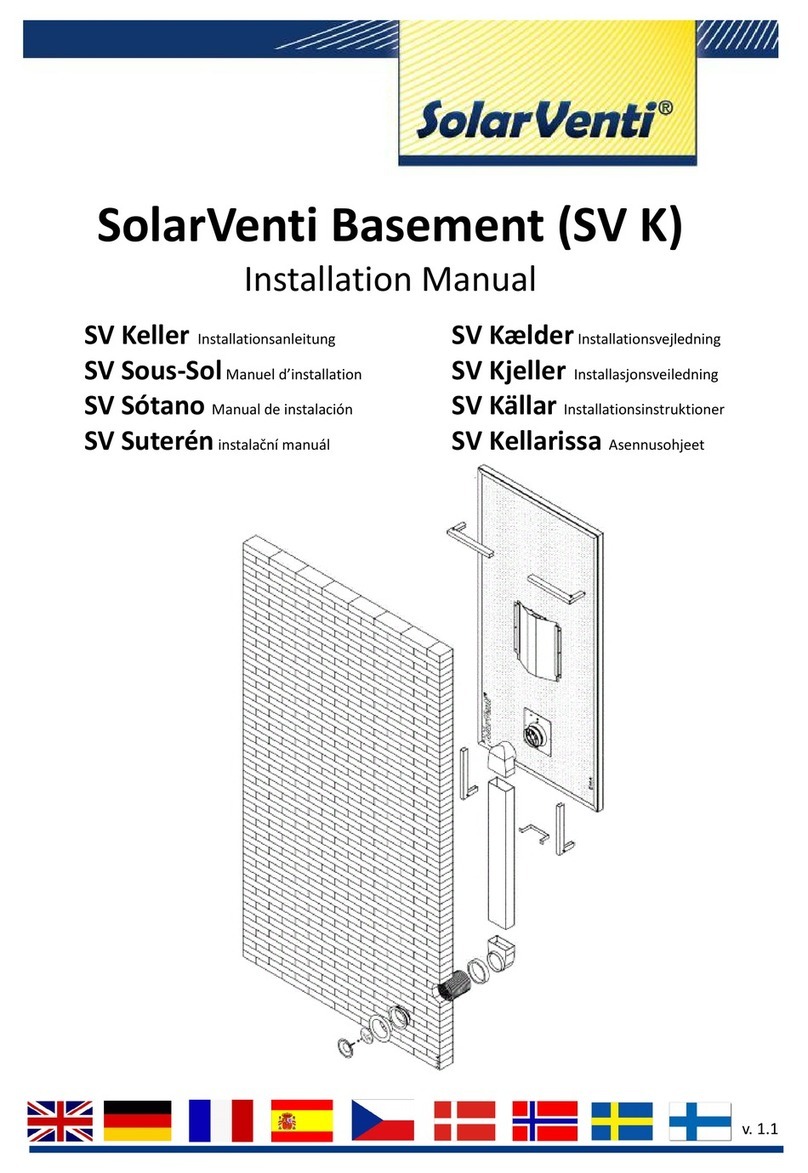
SolarVenti SV K Series Operating and maintenance instructions

SolarVenti
SolarVenti SV3 User guide

SolarVenti
SolarVenti SV14K User manual
SolarVenti
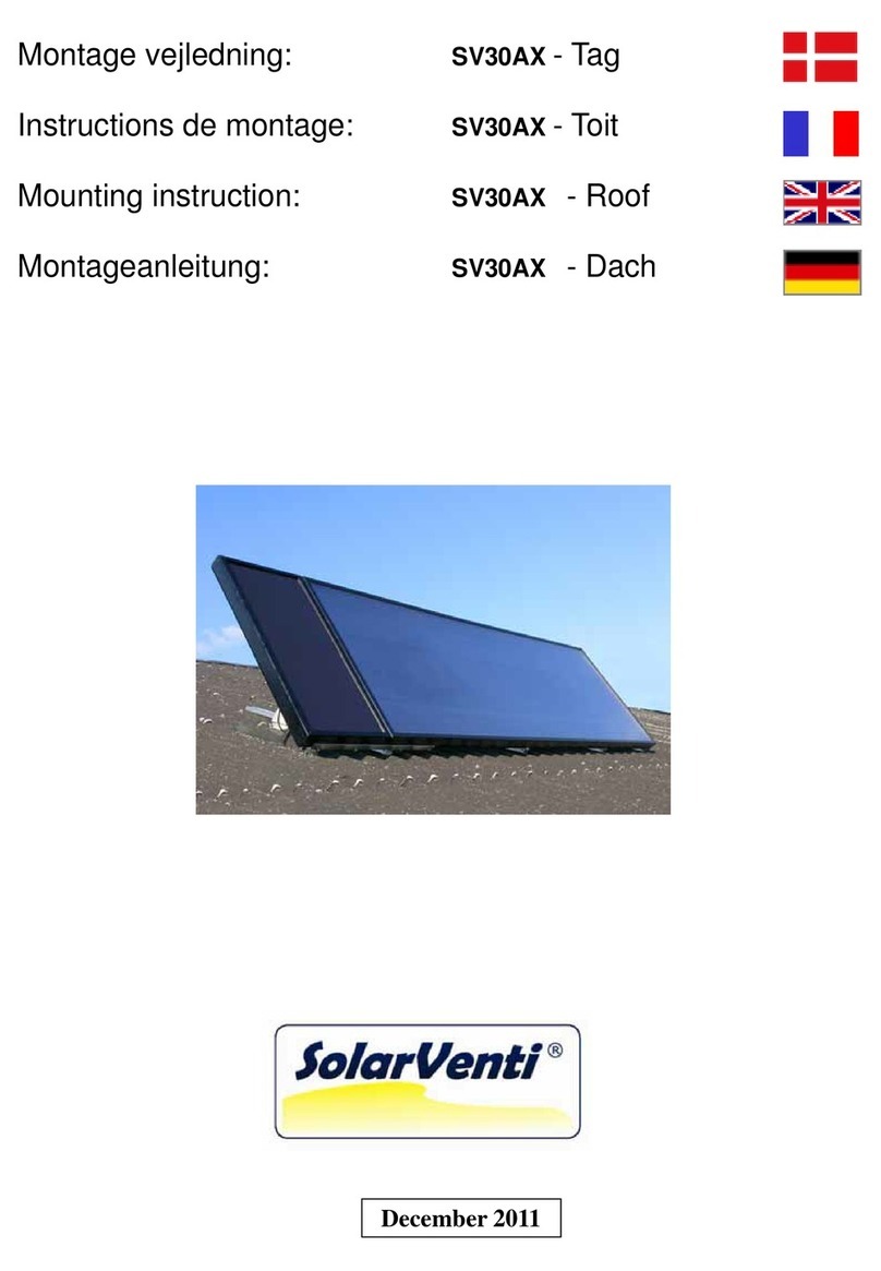
SolarVenti SV30AX User guide
SolarVenti
SolarVenti SV30K User manual
SolarVenti
SolarVenti SV3 User guide
SolarVenti
SolarVenti SV14 User manual
SolarVenti
SolarVenti SV7 User manual
Popular Fan manuals by other brands

Air King
Air King AK905 Specifications
Air King
Air King DL4D Important instructions & operating manual

Soler & Palau
Soler & Palau TD-SILENT SERIES manual
Ray-Dot
Ray-Dot POWER MISER Series quick start guide

Universal Blue
Universal Blue SOLDEN 3050 user manual

HAMPTON BAY
HAMPTON BAY 52" Huntington III owner's manual

