Solatube Ubiflex flashing User manual

Installation Instructions
Solatube Ø 35 cm round
pitched roof Ubiflex flashing

2
Contents
Contents
1. Product Overview........................................................................................................................... 4
1.1 Parts............................................................................................................................................ 4
2. Installation Steps ........................................................................................................................... 5
2.1 Step 1 Roof flashing............................................................................................................ 5
2.2 Step 2 Install the Ubiflex roof flashing............................................................................ 5
2.2.2 Step 2.2.2 High-Tack sealant.......................................................................................... 6
2.2.3 Step 2.2.3 Attach roof flashing tile clips..................................................................... 7
2.3 Step 3 Adjust top tube angle (if required)...................................................................... 7
2.4 Step 4 Install the top tube assembly............................................................................... 8
2.5 Step 5 Install LightTracker flex......................................................................................... 9
2.6 Step 6 Install RayBenders flex.......................................................................................... 9
2.7 Step 7 Fit the roof dome................................................................................................... 10
2.8 Step 8 Attach the brush seal........................................................................................... 10
2.9 Step 9 Install the bottom tube assembly...................................................................... 11
2.10 Step 10 Fit the Natural Effect Lens.............................................................................. 12
Version
20-08-2020
Safety Information
Always observe the safety instructions for the materials and tools to be used.
Always wear the appropriate personal protective equipment (gloves, safety goggles etc.)
We would suggest that any roof works is completed by an experienced roofer.
Always have any electrical works carried out by a certified electrician.
Please note that the installation works is carried out at your own risk.

3
Guarantee and disclaimer
Guarantee
Non-electrical Solatube®
manufacturing defects. Please retain the original proof of purchase to validate the product warranty.
Any costs associated to the installation of any replacement parts covered under the warranty remain
at the expense of the purchaser. Our terms and conditions are available upon request.
Disclaimer
Techcomlight Limited expressly disclaims any liability for any unexpected additional expense arising
as a result of condensation or any water damage resulting from condensation, installation not in
the control of Techcomlight Limited. Techcomlight cannot be held liable for damage to structures
caused as a result of making openings and installing Solatube®systems. Techcomlight assumes no
responsibility or obligation for the failure of an architect, contractor, installer or building owner to
comply with all applicable laws, ordinances, building codes, energy codes, fire and safety codes and
requirements, and adequate safety measures.
Installation instructions reserved. No rights can be derived from this publication.
4
Product overview
1. Product Overview
1
4
2
4
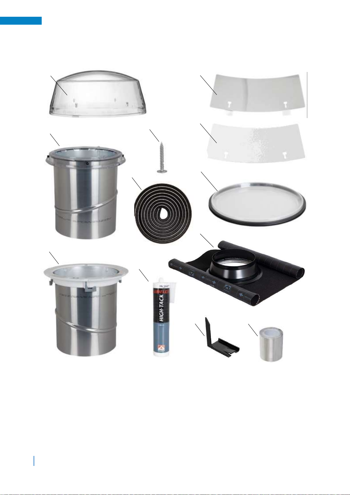
1.1 Parts
1. Flex roof dome
2. Top tube assembly
3. Bottom tube assembly
4. 5 x roof dome screws
5. Brush seal
6. High-tack sealant
7. LightTracker flex
8. 2 x Raybenders flex
9. Natural Effect Lens
10. Ubiflex pitched roof flashing
11. 3 x roof tile clips
12. Roll of aluminium tape
3
7
4
8
4
9
4
4
4
5
6
4
10
4
11
4
12
4
5
Installation Steps
2. Installation Steps
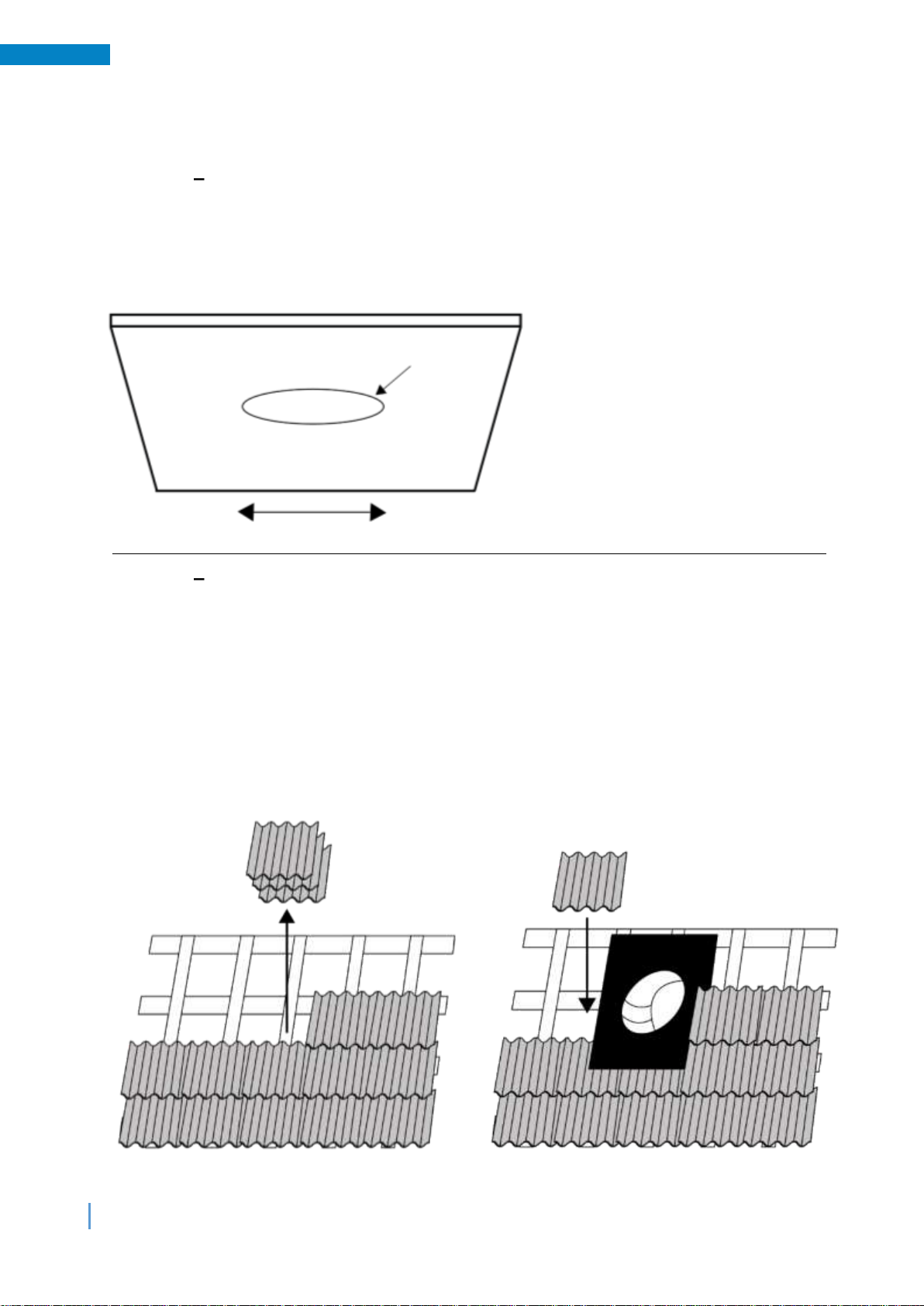
2.1 Step 1 Roof flashing
Determine where you want to install the Solatube from the inside and mark the position
through the ceiling and the roof.
Create a circular opening with a diameter of between Ø 370 - Ø 380 mm through both the
ceiling and roof construction.
2.2 Step 2 Install the Ubiflex roof flashing
Remove sufficient tiles from the roof to allow the flashing to fit down onto the tile battens as
shown below.
Determine the ideal position so that the flashing can be installed beneath the tiles above / to
the sides and down onto the tiles below.
Once the final position is determined, mark and cut any obstructing tile batten to allow the
top tube assembly to fit through the flashing down into the roof void.
Important: Temporarily insert the top tube assembly down through the flashing to help you
to centralise the flashing over the roof aperture created.
1
2
Mark the position and make a circular opening
Opening size between Ø 370 - Ø 380 mm

6
Installation Steps
Tip: The bottom skirt of the Ubiflex flashing is longer than the top.
Fix the Ubiflex roof flashing in place by screwing the top of the flashing to the tile battens.
Create a weather stop by folding the sides and top of the flashing upwards by a few
centimetres.
Dress the bottom skirt of the flashing down onto the profile of the tiles below.
2.2.2 Step 2.2.2 High-Tack sealant
Secure the lower skirt of the flashing down onto the tiles below with the High-tack adhesive /
sealant and tile clips provided.
Tip: Ensure that the tiles below the flashing skirt are free from dust and debris prior to
applying the High-tack adhesive / sealant.
Fit the roof tiles back around the sides and top of the roof flashing.
Note: The sides of the flashing must be overlapped by the roof tiles.
7
Installation Steps
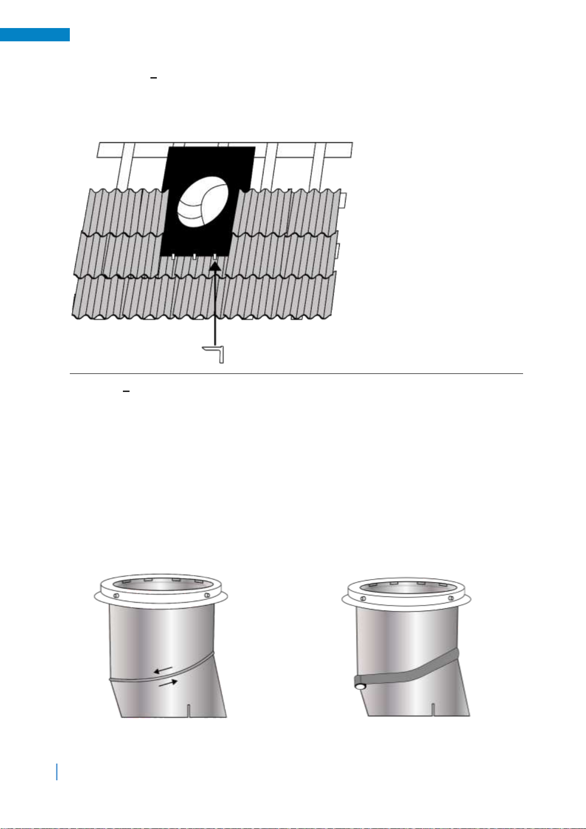
2.2.3 Step 2.2.3 Attach roof flashing tile clips
The three tile clips provided are also used to secure the bottom skirt of the flashing down
onto the roof. Clamp the short "leg" of the clips between two tiles beneath the edge of the
flashing and bend the long "leg" back over the edge of the flashing to clamp it in place.
2.3 Step 3 Adjust top tube angle (if required)
If required, the integral angle within the top tube assembly can be rotated to create an
angle from 0 to 30 degrees to compensate for the pitch of the roof.
How to adjust the integral angle: Carefully peel back the protective film inside the tube
from along the angle seam.
Grasp the top tube with two hands, just below the adjustable angle seam (diagonal).
Use your thumbs and index fingers to rotate the angle section as required.
Adjust the angle so that the top tube assembly aligns with the bottom tube assembly.
Once the angle is correctly set, carefully apply tape to the outside of the tube over the tube
seams and around the angle.
Now remove the transparent protective film from the inside of the top tube assembly.
1
2

8
Installation Steps
2.4 Step 4 Install the top tube assembly
Carefully insert the top tube assembly down through the roof flashing until the transparent
dome ring is correctly seated down onto the top lip of the flashing as shown below.
Fix the dome ring onto the roof flashing using the dome screws provided, screwed through
the four grey spacers from the outside in. The screws will pierce through the flashing and
the inside of the reflective tubing. Be careful not to overtighten the screws as this may cause
damage to the dome ring.
Now remove the transparent protective film from the inside of the top tube assembly.
1
2

9
Installation Steps
2.5 Step 5 Install LightTracker flex
Place the dome upside down on a soft clean surface. Fit the LightTracker flex (this is the
mirrored insert) with the reflective side facing inwards. Align the holes in the LightTracker
over the corresponding tabs inside the dome and slide the LightTracker flex downwards to
secure it in place.
Note: If the sunlight from the south is blocked, do not mount the LightTracker flex in the
dome!
2.6 Step 6 Install RayBenders flex
Fit the two RayBenders flex inserts (these are the transparent ribbed insert) onto the
remaining tabs inside the dome with the smooth sides facing inwards and the ribbed sides
against the dome. Align the holes in the RayBenders with the corresponding tabs inside the
dome and slide the RayBenders downwards to secure them in place.
10
Installation Steps
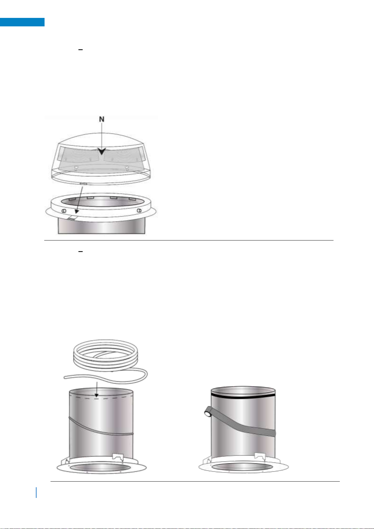
2.7 Step 7 Fit the roof dome
Snap the dome onto the dome ring using the 4 snap closures. Ensure that all four
connecting points are properly engaged.
Important: Fit the dome with the LightTracker flex on the north side (facing south).
Tip: If you want to remove the dome again, insert the end of a wide screwdriver into the
opening of the snap fasteners and pry it off one by one from below.
2.8 Step 8 Attach the brush seal
Stick the brush seal strip around the outside of the bottom tube assembly or uppermost
extension tube, just below the top of the tube as shown below. Using the entire sealing strip,
wrap the strip around the tube keeping the rings tightly together as shown.
Note: if additional extension tubes are being used this operation must be performed around
the top of the uppermost extension tube.
Once the angle is correctly set, carefully apply tape to the outside of the tube over the tube
seams and around the angle.
2
1
11
Installation Steps
2.9 Step 9 Install the bottom tube assembly
If required, adjust the adjustable angle within the bottom tube assembly as previously
shown. Seal all external tube seams including the angle by applying tape over the seams on
the outside of the tube.
Prior to installing the bottom tube assembly carefully apply tape apply to the outside of the
tube over the tube seams and around the angle.
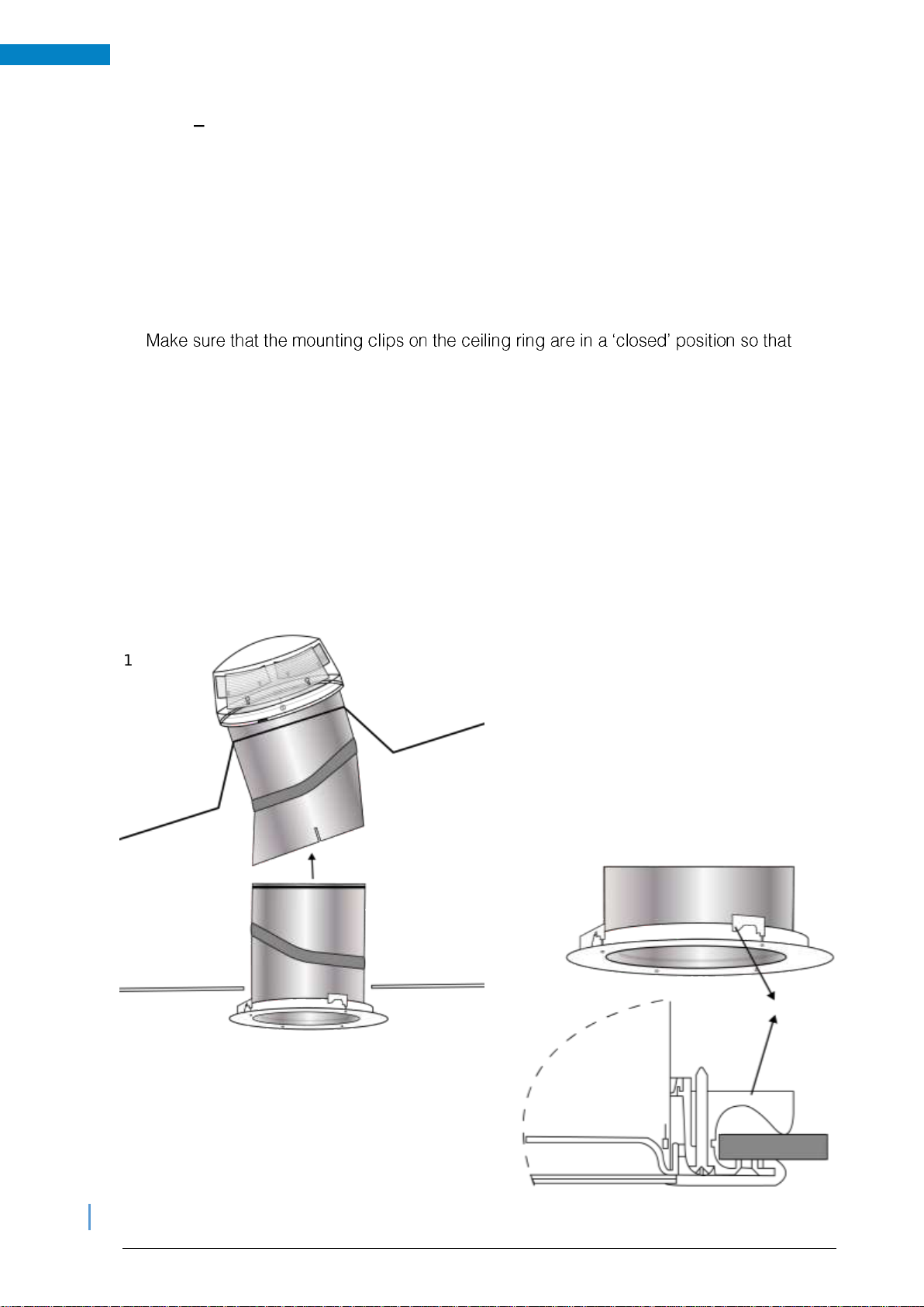
Carefully push the bottom tube assembly up through the opening created in the ceiling and
up into the inside the top tube assembly, until the ceiling ring is flush with the ceiling.
Tip:
they fit through the ceiling opening.
Tighten the four fixings screws within the ceiling ring which will engage the mounting clips,
tightening them down onto the ceiling to clamp the bottom tube assembly in place.
Alternatvely, if the mounting clips cannot be used (for example with a concrete finish or a
double boarded ceiling), or if the ceiling ring does not fit tightly enough, it can be fixed with
screws through the pre-defined fixing points moulded into the ceiling ring. The pre-defined
fixing points in the ceiling ring must be pre-drilled for the screws prior to being fixed in this
way.
Now remove the transparent protective foil from the inside of the bottom tube assembly.
1
2
12
Installation Steps
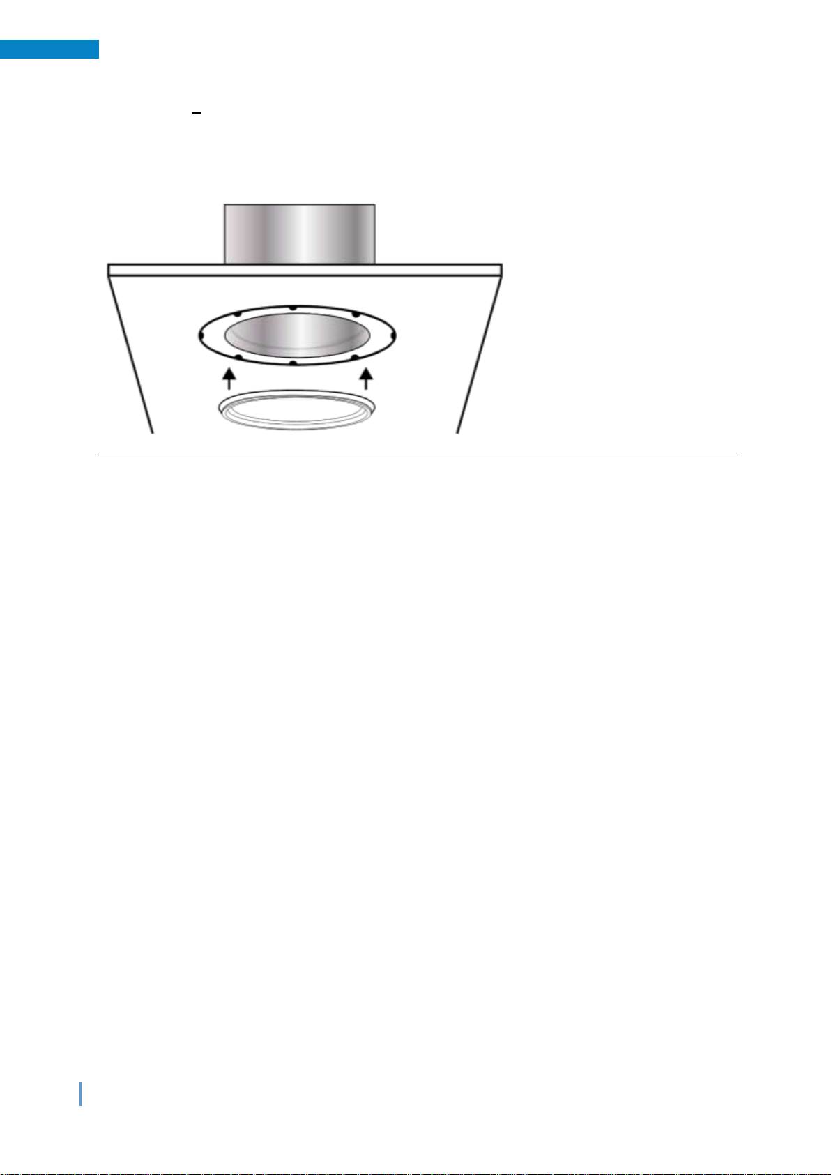
2.10 Step 10 Fit the Natural Effect Lens
Press the Natural Effect Lens with the clear plastic tab facing downwards securely into the
recess between the reflective tube and the plastic ceiling ring. The Natural Effect Lens can
be easily removed if required by carefully pulling down on the clear plastic tab.
Please see the separate instructions for the installation of the ceiling diffuser.

Table of contents
Popular Light Fixture manuals by other brands

Lightolier
Lightolier Coffaire II CFH1GPF specification

Verilux
Verilux VT05 user manual

Hama
Hama Xavax 00111973 operating instructions

ETI Solid State Lighting
ETI Solid State Lighting 535091610 Use and care guide

Larson Electronics
Larson Electronics HAL-16BS-1X185LED-CPR-100 Instruction guide

Lightolier
Lightolier 6700S2UEMNY specification


WAC Lighting
WAC Lighting WTK-1014 Installation instruction

Elation
Elation COLOUR PENDANT user manual

olympia electronics
olympia electronics OLY-1004/WL quick start guide

Cooper Lighting
Cooper Lighting LUMARK GP specification

PhotonStar
PhotonStar Ceiling Star SM installation instructions

JONATHAN Y
JONATHAN Y JYL6005A manual