Solem LR-MB User manual
L’EXPERT DE L’IRRIGATION CONNECTÉE
LR-MB
INSTALLATION GUIDE
APPLICATION MySOLEM GRATUITE
FREE MySOLEM APP
Gère jusqu’à 25
produits d’irrigation
Manages up to 25
irrigation products
+ 33 (0)4 67 59 24 25 solem.fr | commer[email protected] | ZAE La Plaine - 5, rue Georges Besse - 34830 CLAPIERS
FONCTIONNEMENT
Wi-Fi 802.11 b/g, WPA2-PSK,
WPA, WEP
Bluetooth®Smart 4.0 Low Energy
Communication en radio LoRa
DIMENSIONS
Largeur : 8 cm
Hauteur : 8,2 cm
Profondeur : 1,3 cm
INSTALLATION
External transformer (230/12VDC)
Up to 25 LoRa devices connectable
To be installed indoors or outdoors
under shelter
Environement : from 0°C to 50°C
FONCTIONNEMENT
Wi-Fi 802.11 b/g, WPA2-PSK,
WPA, WEP
Bluetooth®Smart 4.0 Low Energy
Communication by LoRa radio
DIMENSIONS
Width : 8 cm
Height : 8,2 cm
Depth : 1,3 cm
INSTALLATION
Transformateur (230 / 12VDC) externe
Jusqu’à 25 appareils d’irrigation
LoRa associables
À installer en intérieur ou extérieur
sous abris
Température d’utilisation :
de 0°C à 50°C
CARACTÉRISTIQUES TECHNIQUES TECHNICAL FEATURES
LR-MB
LE RELAI Wi-Fi/LoRa
Wi-Fi/LoRa RELAY
41FOUR-LRMB-X1[0617]
LR-MB
LE RELAI Wi-Fi/LoRa
Wi-Fi/LoRa RELAY
THE CONNECTED IRRIGATION EXPERT
L’EXPERT DE L’IRRIGATION CONNECTÉE
Gestion
en temps réel
Real time
management
5 fois plus
de portée
5 times
more range

2
The LR-MB is a relay Wi-Fi - Bluetooth®/ LoRaTM sector, remotely controllable.
It can manage up to 25 « LR-IP » battery operated irrigation modules and/
or « LR-FL » owmeter modules from the LR range, from anywhere with a
simple internet connection.
PRESENTATION
Recommandations :
An LR product installation requires a pre-audit phase in order to check the
connection of the products in their intended positioning.
To optimize the connection between the « LR-MB » and the LR modules, it is
strongly recommended :
1 - Install LR modules in buried plastic manholes and to position them as
high as possible in the eye.
2 - Position the « LR-MB » or its remote antenna as high as possible, with a
clear environment.
3 - To test the LoRaTM connection between « LR-MB » and the modules using
the test tool present in the MySOLEM application. (see page 12)

3
INFORMATIONS
LoRa connection periodicity between « LR-MB » and his modules is 3
minutes.
Remotely, each modication of program or manual control will be eective
after a delay of 3 minutes.
On the « LR-FL » module :
- Recording of the count, every 15 minutes.
- Feedback, every 3 minutes.

4
DOWNLOADING
1. On your smartphone and/or tablet, go to the « App Store » and/or
« Google Play » app.
2. Look for « MySOLEM » in the search bar.
Step 1
3. Download the MySOLEM application.
MySOLEM
4. Once installed, activate the Bluetooth® of your smartphone and/or tablet

5
CREATE AN ACCOUNT
1. On your smartphone and/or tablet,
launch the « MySOLEM » application
2. Enter the « My Accounts » tab
Step 2
3. If you already have an account, ll in your
credentials. Otherwise, follow the steps to
create an account.
6
INSTALLATION LR-MB
Step 3
1. Make sure the place where you want to install the « LR-MB » is covered by
the Wi-Fi connection of your internet box.
2. Screw on the antenna, and connect the 230VAC power supply provided
with the « LR-MB ».
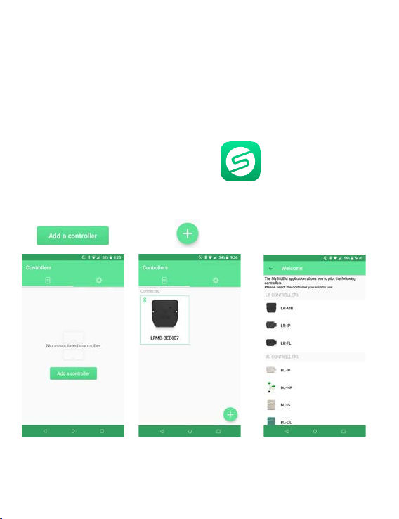
3. Launch the MySOLEM application from
your smartphone and/or tablet.
4. Press on
or
No module
installed
Modules are already
installed
5. Select LR-MB.
7
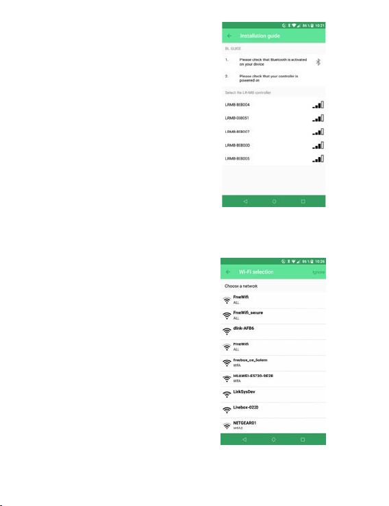
7. Select the Wi-Fi network access to
which you want to connect your
« LR-MB » by clicking on the corresponding
line or « Ignore » if your
« LR-MB » has already been assigned to
a Wi-Fi network.
8. Enter the password for the Wi-Fi
network access point, then conrm.
To check that your « LR-MB » is correctly
connected to the Wi-Fi network, check
that the LED on the front panel is solid
green.
6. Select the « LR-MB » you wish to
install from the list of available modules
under « Select the LR-MB programmer »

8
ASSOCIATION MODULES LR
Step 4
2 ASSOCIATION MODES :
1/ Factory pre-association
In this mode, the « LR-MB » is pre-associated at the factory with the other LR
modules. The whole form a custom KIT LR.
Power up the modules and test the LoRaTM connection (see page 12)
2/ Manual association
See step 5
9
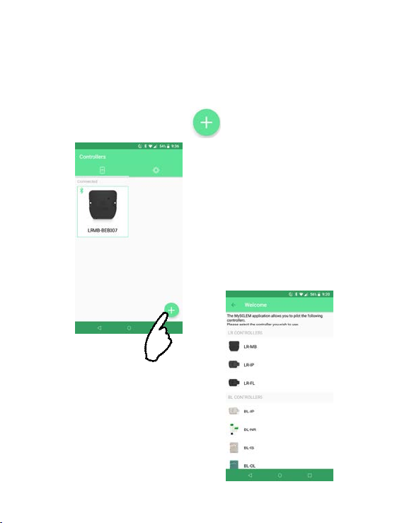
ASSOCIATION Manual
1/ Position the LR module within range of « LR-MB » (<10m)
2/ Go to the home screen, press on
3/ Select the type of
module to install.
Step 5

10
4/ Select your module from the list of
programmers.
The displayed number corresponds to the
« Default name » present on his product label.
Once the selection is made,
the module(s) appears

11
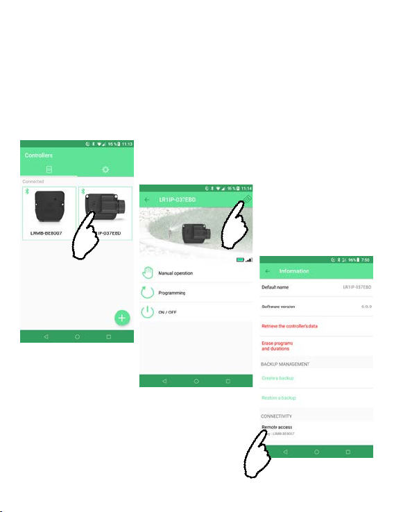
5/ Select the module you just added by
tapping it.
Press on top right to access the
product information page.
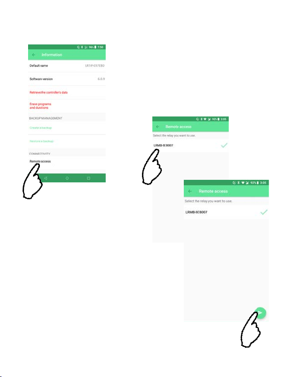
12
6/ Pairing :
Tap « Remote Access »
7/ Select your « LR-MB »
8/ Press to validate the
operation.
13
Once your network is made up: « LR-MB » installed and connected to
the Wi-Fi network, modules associated with « LR-MB », you can test the
LoRaTM connection between the « LR-MB » and the modules to validate the
positioning of your products.
LoRaTM CONNECTION TEST

14
1/ Test the LoRaTM connection with a support on
2/ The message
indicates that the LoRaTM connection
between the « LR-MB » and the module
is reliable.
In case the connection is not reliable,
move the module closer to the « LR-MB »,
or vice versa, and repeat the procedure.

15
LoRaTM CONNECTION STATUS
Connection < 5mn
5mn < Connexion < 10mn
Connection never etablished
By pressing on one of the icons, you obtain a
message giving the state of the LoRaTM connection.
Example :
Connection > 10mn
Non-transmitted changes
These icons give the status
of the last LoRaTM connection
between the « LR-MB » and the
LR modules.

16
LED INFORMATIONS
INFORMATIONS ON THE STATUS OF THE LR-MB LED
• Green LED : normal running
• Green LED ashing : Firmware update in progress
• Red LED ashing 3 times :
Possible causes :
1/ Loss of Wi-Fi access point (box) or connection not etablished.
Restart your box and the product.
2/ During initialization, the password entered is not correct.
Trick : Enter the password of the box in a « Notes » application on your mobile.
Copy the password with a long press and paste it into the corresponding eld.
Repeat the initialization procedure.
3/ During initialization, the product may be too far from the box : bring the
product closer.
• Red LED ashing 2 times : alarm time : the LR-MB is no longer on time.
If your product is connected to the MySOLEM platform, the time setting
will be automatic. Otherwise, connect to the LR-MB from the application
and check that the message « Synchronization OK » is displayed.
•
• LED o : the product is not powered.

17
MOUNTING
OUTDOOR ANTENNA
In the case of mounting the antenna outdoors with the optional extension
of 5 or 10 meters, we recommend protecting the antenna with a plastic tube
with an internal diameter of 15mm minimum. This tube will be clogged on
his upper part to protect the antenna from the rain. The cord will have to be
protected by a sheath.
INSTALLATION LR-IP/FL
Refer to the respective notices.

18
CHARACTERISTICS
Techniques
Use :
Permissible humidity : 90% (relative humidity)
Ambient temperature of product use : 0°C to 50°C
Guarantee : 2 years
Dimensions :
Width 8 cm x Height 8.2 cm x Depth 1.3 cm
Alimentation :
Power supply unit : INPUT : 100-240V ~ 0.2A Max
50/60Hz OUTPUT : 12V 0.5A
Frequency band used and power emitted max :
Bluetooth® : [2400-2483.5]Mhz, 1mW
Wi-Fi : 2.4Ghz , 25mW
LoRaTM : [868-868.6]Mhz, 25mW

19
READ THE FOLLOWING SAFETY INSTRUCTIONS CAREFULLY BEFORE
INSTALLING OR USING THE LR-MB. BE SURE TO RESPECT RIGOROUSLY
EMPLOYMENT PRECAUTIONS.
The LR-MB must be installed indoors or under cover.
Install your product so that the socket outlet is near the equipment.
The socket is a disconnecting device, in case of problem, it must be easily
accessible at all times. Make sur the outlet on which your power transformer
is plugged has overcurrent protection and circuit breaker type short circuit
protection 16A.
Use only the power supply unit provided with the product (model MU06-
T120050-C5),
INPUT : 100-240V ~ 0.2A Max 50/60Hz OUTPUT : 12V 0.5A

20
~
VI
The symbol « CE » indicates that this device complies with the European
standards on safety, health, the environment and the protection of the
user. Devices with the symbol « CE » are intended for sale in Europe.
This symbol indicates that these types of electrical and electronic devices
must be discarded separately in European countries. Do not dispose of this
device with your household waste. Please use the collection and recycling
points available in your country when you no longer need this device.
This symbol indicates that the supply voltage is a DC voltage.
This symbol indicates the polarity of the DC supply voltage.
This symbol indicates that the supply voltage is an AC voltage.
This symbol indicates that the power supply is intended for indoor use only.
This symbol indicates that the power supply has double insulation class 2.
This symbol indicates that the output of the external pwer supply is level 6.
This symbol indicates that the product uses a LoRa technology radio.
Table of contents
Other Solem Relay manuals


