Safety Switching Devices
Emergency-Stop Relay
PI 0067-0703 E SNO 2012
1/6
Basic unit for Emergency-Stop and
Safety Gate Applications
•Basic unit accordingtoDIN EN 60204-1 and EN 954-1
•EN 954 category 4
•Stop category 0 acc. EN 60204-1
•WithcrossmonitoringandRESETkeymonitoringandsimultaneitycheck
•Single or dual channel input control circuit for contacts or semiconduc-
tors
•6NOsafetycontacts,4NCcontrolcontactspositivelydriven
•OSSDcompatible
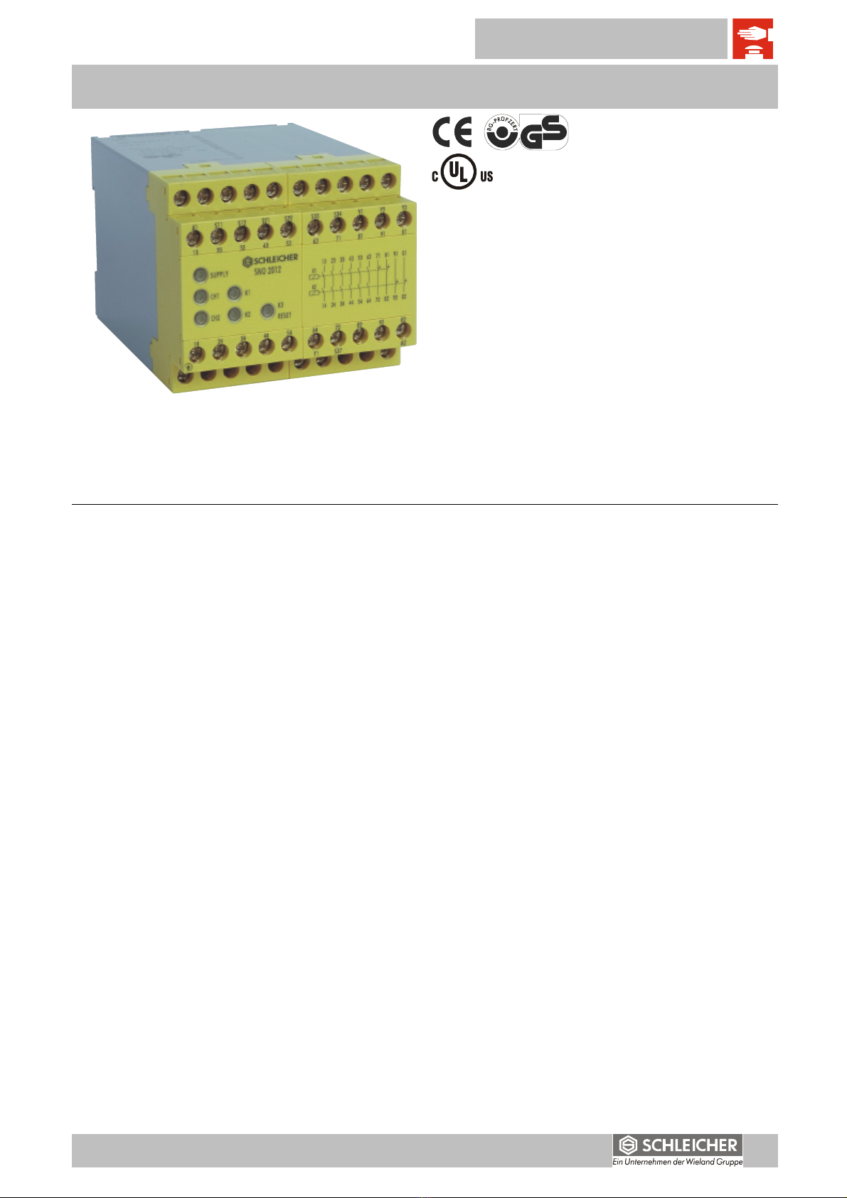
Front View
SUPPLY LED green
CH1 LED green
CH2 LED green
K1 LED green
K2 LED green
K3 LED green
1gg
Device and Function Description
The Device is a dual-channel safety switching device for emergency stop equipment conforming to EN 60204-1, with self-monitoring on each ON-OFF cycle and
positively driven relays. After the supply voltage is applied to terminals A1/A2, and if the E-Stop momentary contact switch is not activated, the control logic is
energized with the RESET switch (LED K3 is illuminated). This triggers the internal relays K1 and K2. The latter becomes self locking through their own con-
tacts. After this switch-on phase, the six enabling current paths, which are intended for the output, are closed (terminal connections 13 to 63 / 14 to 64) and the
four control contacts are opened (terminal connections 71 to 01 / 72 to 02). Five LEDs provide a display, and these LEDs are associated with the safety chan-
nels CH1, CH2 and the supply voltage. If the E-Stop switch is activated, the current leads for the K1 and K2 relays are interrupted. The enabling current paths
at the output are opened and the control contacts are closed. The control contacts 71/72 and 81/82 are related to the internal relay K1, 91/92 and 01/02 to the
internal relay K2. This feature allows an additional diagnosis of the internal status of the device by using external devices conected to these terminals. With a
two-channel connection of the E-Stop switch and cross monitoring wiring of the E-Stop circuit, it is possible to monitor the presence of a short circuit between
the connected cables (cross monitoring) and ground faults. An internal electronic circuit protects the emergency-stop relay from damages. After eliminating the
fault the item will return into operation after about 3 s.
RESET key monitoring
The SNO 2012-xx is equipped with (or without) the monitoring feature for the RESET key. For the specific use in the emergency-stop applications with moni-
toring of the the RESET key, the latter must be connected to terminals S12/S34 and terminals Y1/S37 have to be jumpered. For those applications with protec-
tive gates a manual RESET (terminals S12/S34 ) or an automatic RESET can be performed according to the requirements of the safety function. Where an
automatic RESET must be performed, it is necessary to connect terminals S12 and S34 and let terminals Y1 and S37 unjumpered. In case of RESET key
monitoring, the device can be enabled with the falling edge of the signal at the RESET key (RESET released). This only allows a manual START of the device.
An automatic START is with these connections not possible (see also function diagram). If the RESET key is not monitored the device can be used for those
dynamic applications (such as protective gates) where an automatic START is necessary. In this case the device can be enabled with the rising edge of the
signal (closing the RESET key): connections S12 to S34 and Y1/S37 open terminals.
Simultaneity check
The use of safety limit switches for single or dual channel circuit in the protective gate application depends from the required safety level. The SNO 2012-xx
features a dual channel control and asimultaneity
checkofthe limit switches on request.Preconditionfor a simultaneity check ts
≈
0,5s
isthepositionofthelimitswitches.
Thelimitswitchesmustbepositionedso that channel 1 (terminals S11/S12) has toclosebeforechannel2(termi
nals S21/S22) does. If channel 2 closes before channel 1
the simultaneity check is switched off (ts=
∞
).
Correct use of the system
The SNO 2012 is a safety switching device. It is used as a base unit for monitoring control units such as emergency stop buttons and position switches. Emer-
gency stop devices and guards are part of safety-related equipment on machines to protect from injuries and damage to materials and machines.
Notes
•
The input circuit allows connecting of sensors with self testing semiconductor outputs (e.g. light barriers with OSSD).
•The safety category according to EN 954-1 also depends from the external circuit, the choice of the transducer_ and is location on the machine.
•Insulation on external wiring should not be cut back more than 8 mm.
•
To multiply the enabling current paths, the expansion units or external contactive elements with positively driven contacts can be used.
•External fuse protection for the device and the contacts should not exceed 6 A type gG.
Please observe instructions from safety authorities.