Solera 434730 Installation instructions
1
lc i1.c om 574 - 5 37- 8 9 0 0 Rev:0 7.19 .18
Solera®
Power Awning 18V
Installation and Owner’s Manual
(For Aftermarket Applications)
CCD-0001260
Table of Contents
Introduction ............................................ 2
Features ............................................... 2
Parts List ................................................ 2
Safety ................................................... 3
Prior to Installation ..................................... 3
Resources Required ................................... 3
Awning Rail Installation ................................ 4
Awning Installation ..................................... 5
Securing The Fabric .................................... 7
Operation ............................................... 8
Extending the Awning ................................. 8
Retracting the Awning ................................. 9
Adjusting Pitch ......................................... 9
Troubleshooting ...................................... 10
Manual Override ..................................... 10
Solera®
Power Awning 18V
Installation and
Owner’s Manual
(For Aftermarket Applications)
Solera Power Awning Troubleshooting ............. 11
Maintenance - Solera Awnings ...................... 12
Fabric Care .......................................... 12
Notes .................................................. 12
Solera Power Awning 18V Kits
Part # Description
434729 Solera Power 18V 69” Kit, Black
434730 Solera Power 18V 69” Kit, White

2
lc i1.c om 574 - 5 37- 8 9 0 0 Rev:0 7.19 .18
Solera®
Power Awning 18V
Installation and Owner’s Manual
(For Aftermarket Applications)
CCD-0001260
Introduction
The Solera®Power Awning with an 18V Power Pack
features an internal motor to steadily operate the awning
and a unique, rechargeable battery that ts inside the
Solera Power Awning arm. Additionally, the pitch arm
assembly allows for rain dump and adjustable pitch
features. The pitch arm assembly also provides added
stability.
Additional information about this product can be obtained
from lci1.com/support or by downloading the free myLCI
app. Replacement component parts can be ordered from
store.lci1.com/ or by using the myLCI app. The myLCI app
is available on iTunes®for iPhone®and iPad®and also on
Google Play™for Android™users.
iTunes®, iPhone®and iPad®are registered trademarks of
Apple Inc.
Google Play™and Android™are trademarks of Google Inc.
Features
• Save 1-2 hours of additional installation expense as
there is no need to wire this awning directly in to the RV’s
power supply.
• Waterproof switch offers easy, push-button operation.
• Operates 22-25 times before needing a simple plug-in
recharge.
• Faster extend and retract time.
• Includes Easy Access AC charging adapter that plugs
into any 110V outlet.
• Easy DIY installation; no internal wiring needed to the
RV’s main power source.
Parts List
PN Description—Common Qty
237315 Rivet, AL/AL, Klamp-Tite® (3/16” X 1.3”) 8
281079 Screw, Zn, Hex Washer SLFDR, Blk (#6-20 X 1/2”) 2
298760 Pin, 0.093” X 2-5/16” Zn Hairpin Cotter 4
347119 Pin, 1/8” X 3”; Zn, Cotter 2
384905 Screw, SST, PNH Plain PH, (#10 - 32 X 2 1/2”) 2
384906 Nut, Nylock Plain, (#10 - 32) 2
438247 Cable Tie, Standard, NYL - 30 – White 2
CCD-
000-1260
Solera Power Awning 18V Manual 1
PN Description—434729 Qty
276611 Screw, Zn, PNH SQ SLFDR, Blk HD (#8-18 X 1/2”) 6
281154 Flat Awning, Support Arm Assy – Black 1
346891 Rivet, AL/AL, Black (3/16” X .450”); 6
360575 Screw, Zn, Waxed PNH, SQ F St, Blk (#8 - 32 X 1/2”) 2
384965 Bracket, Upper Solera Power 2.500 IN-PC Blk 2
390806 Label, Solera Power – Black 2
423751 Cap, End Power Awning - PC Black 2
656484 Flat Awning, Support Arm Assy - BP - PC Black 1
672050 Drive Head Assy w/Gear Pack w/Override - Regal -
Awning Black
1
672052 Idler Head Assy w/Gear Pack w/Override - Regal -
Awning Black
1
PN Description—434730 Qty
281152 Flat Awning, Support Arm Assy - White 1
299630 Screw, Zn, Waxed PNH, SQ F ST (#8 - 32 X 1/2”) 2
346890 Rivet, AL/AL, White, (3/16” X .450”), 6
384964 Bracket, Upper Solera Power 2.500 IN-PC White 2
390805 Label, Solera, Power – White 2
423750 Cap, End Power Awning - PC White 2
656483 Flat Awning, Support Arm Assy - BP - PC White 1
672049 Drive Head Assy w/Gear Pack w/Override - Regal -
Awning White
1
672051 Idler Head Assy w/Gear Pack w/Override - Regal -
Awning White
1
675906 Screw, Zn, PNH SQ SLFDR, (#8-18 X 1/2”) 6

3
lc i1.c om 574 - 5 37- 8 9 0 0 Rev:0 7.19 .18
Solera®
Power Awning 18V
Installation and Owner’s Manual
(For Aftermarket Applications)
CCD-0001260
Safety
THIS MANUAL PROVIDES OPERATIONAL
PROCEDURES FOR THE SOLERA POWER AWNING
WITH AN 18V POWER PACK. OPERATING THE
SOLERA POWER AWNING IN ANY OTHER MANNER
THAN DESCRIBED MAY RESULT IN PERSONAL
INJURY, DAMAGE TO THE RECREATIONAL VEHICLE
UNIT OR THE AWNING ASSEMBLY AS WELL AS
VOIDING THE LIPPERT COMPONENTS LIMITED
WARRANTY.
THE “WARNING” SYMBOL ABOVE IS A SIGN THAT
AN INSTALLATION PROCEDURE HAS A SAFETY
RISK INVOLVED AND MAY CAUSE DEATH OR
SERIOUS INJURY IF NOT PERFORMED SAFELY AND
WITHIN THE PARAMETERS SET FORTH IN THIS
MANUAL. ALWAYS WEAR EYE PROTECTION WHEN
PERFORMING THIS INSTALLATION PROCEDURE.
OTHER SAFETY EQUIPMENT TO CONSIDER
WOULD BE HEARING PROTECTION, GLOVES, AND
POSSIBLY A FULL FACE SHIELD, DEPENDING ON
THE NATURE OF THE INSTALLATION PROCEDURE.
MOVING PARTS CAN PINCH, CRUSH OR CUT. KEEP
CLEAR AND USE CAUTION.
THE 18V POWER PACK RECHARGEABLE BATTERY
CONTAINS LITHIUM WHICH IS A HAZARDOUS
MATERIAL. DO NOT THROW IN THE TRASH
OR WITH OTHER HOUSEHOLD RECYCLABLE
MATERIALS. THE BATTERY MUST BE DISPOSED OF
PROPERLY AT A HOUSEHOLD HAZARDOUS WASTE
COLLECTION SITE.
Prior to Installation
If the unit does not have a pre-installed awning rail, one
must be purchased.
All screws supporting the awning assembly must have a
backer within the structure of the wall of the unit. Refer to
the unit manufacturer for proper location.
This manual will refer to the “drive side” and “idler side”
throughout for various instructions. The “drive side” is the
right hand side of the awning when facing the awning from
the exterior of the unit. The “idler side” is the left hand side
of the awning when facing the awning from the exterior of
the unit.
Solera 18V Tall Arm (69”) Adjustable Pitch Arms require:
• 69” of unobstructed area from the awning rail straight
down.
• Minimum clearance of 2 ½” between the awning rail and
the top of the entry door.
Resources Required
• 2-3 people, depending on the task
• Cordless or electric drill or screw gun
• Appropriate drive and drill bits
• Socket wrench
• ⁄” socket
• Rivet gun (if needed)
• Locking pliers
• Ladder
• Non-permanent method of marking
• Silicone sealant or butyl tape
• Screwdriver
• Silicone lubricant
• Scissors/utility knife
• Wire cutters/strippers
• #6 x ½” hex head screws
• #10 x ¾” screws
• #12 1 ¼” screws
• #14 x 1 ¼” screws
4
lc i1.c om 574 - 5 37- 8 9 0 0 Rev:0 7.19 .18
Solera®
Power Awning 18V
Installation and Owner’s Manual
(For Aftermarket Applications)
CCD-0001260
Awning Rail Installation
If installation of an awning rail is required, complete the
following steps.
1. Position the awning rail along the line where roof and
wall meet OR:
A. For pitched awnings: A minimum of 6" above doors or
windows.
B. For at awnings: A minimum of 2 ½" above doors or
windows.
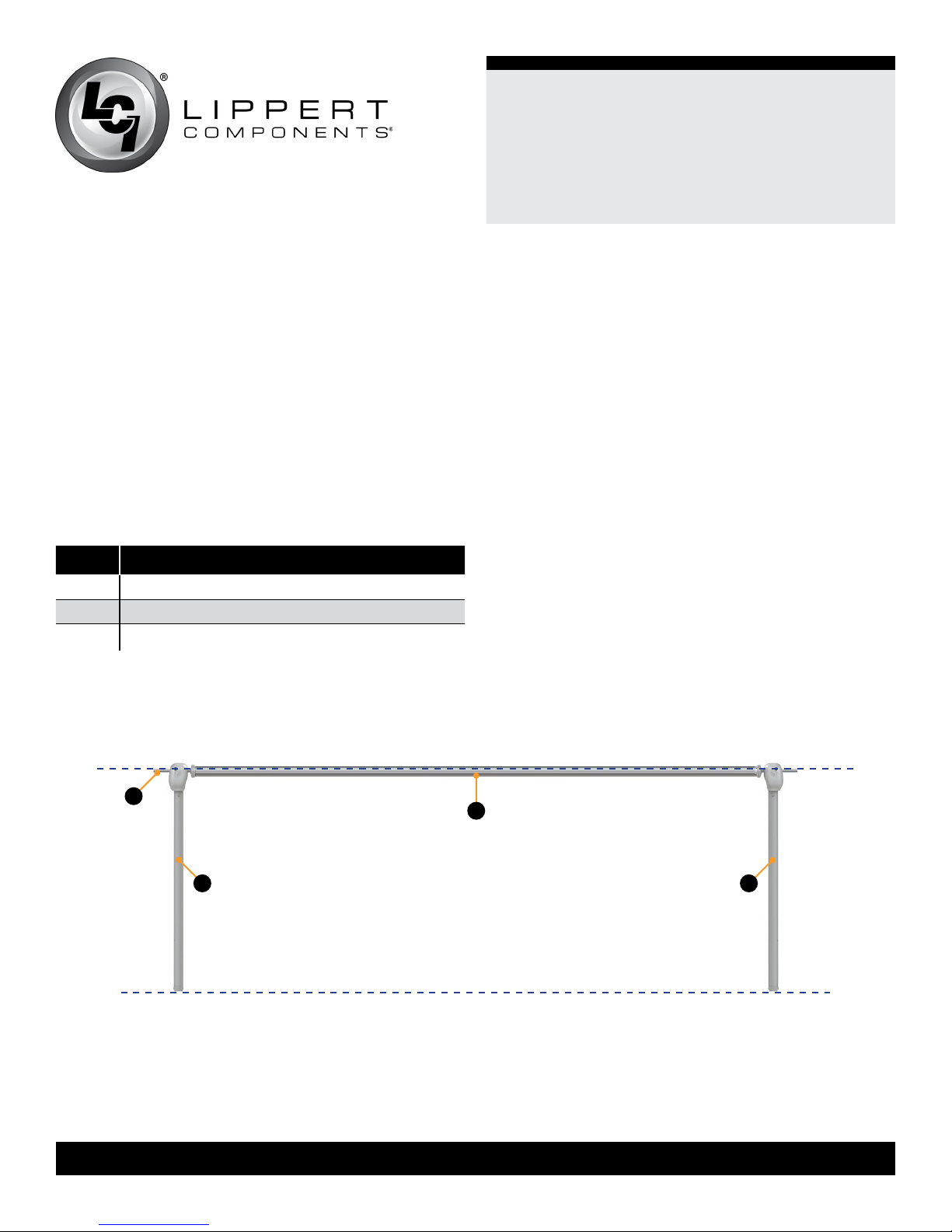
NOTE: The awning rail must be level and parallel with the
oor line of the unit (Fig.1).
Letter Description
A Awning Rail
B Support Arm Assembly
C Roll Tube Assembly
Fig.1
front facing view
floor line
A
B B
C
2. After determining the awning rail’s proper location, mark
its position with a non-permanent method of marking.
3. Seal the back of the awning rail.
4. Align the awning rail on the wall and secure with #10 x
¾" screws, using all fastener holes.
5
lc i1.c om 574 - 5 37- 8 9 0 0 Rev:0 7.19 .18
Solera®
Power Awning 18V
Installation and Owner’s Manual
(For Aftermarket Applications)
CCD-0001260
Awning Installation
1. On the awning rail, mark the position of the centerlines
of the support arm assemblies. Make sure the support arm
assemblies will not interfere with any lights, vents or other
obstructions.
2. Using a non-permanent method of marking, mark a
perpendicular line from the awning rail down to the oor
line. This is the centerline of the support arm assembly
(Fig.2).
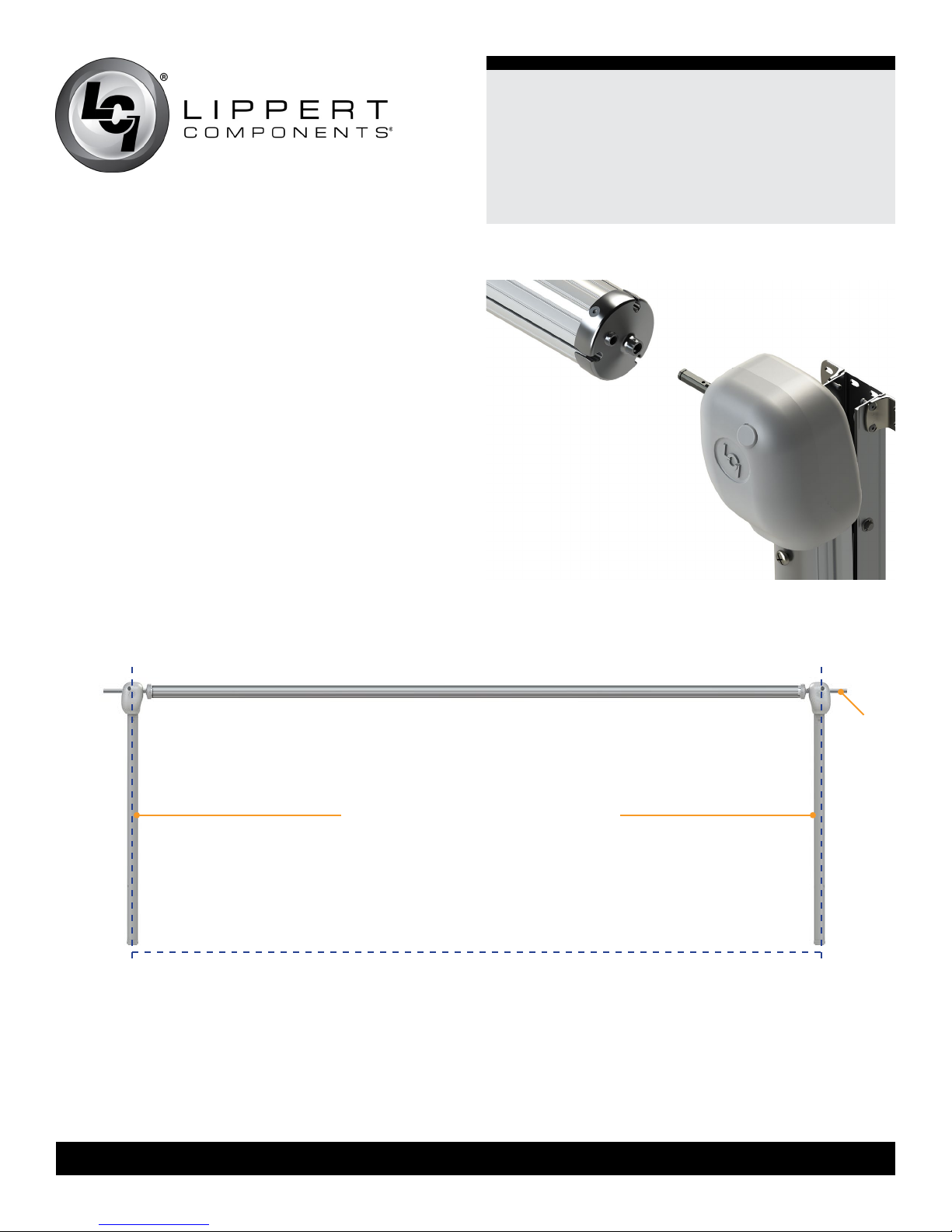
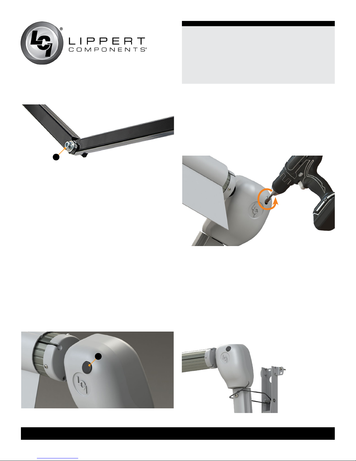
3. Insert the drive head assembly shaft into the end cap
(Fig.3). Align the holes and secure with a waxed screw.
Repeat process for idler head assembly at opposite end.
NOTE: Keep the head of the wax screw ⁄” from fastened
to avoid compromising the structural integrity of the wax
screw.
Fig.2
Fig.3
awning width is from centerline to
centerline of support arm assemblies.
floor line
awning
rail

6
lc i1.c om 574 - 5 37- 8 9 0 0 Rev:0 7.19 .18
Solera®
Power Awning 18V
Installation and Owner’s Manual
(For Aftermarket Applications)
CCD-0001260
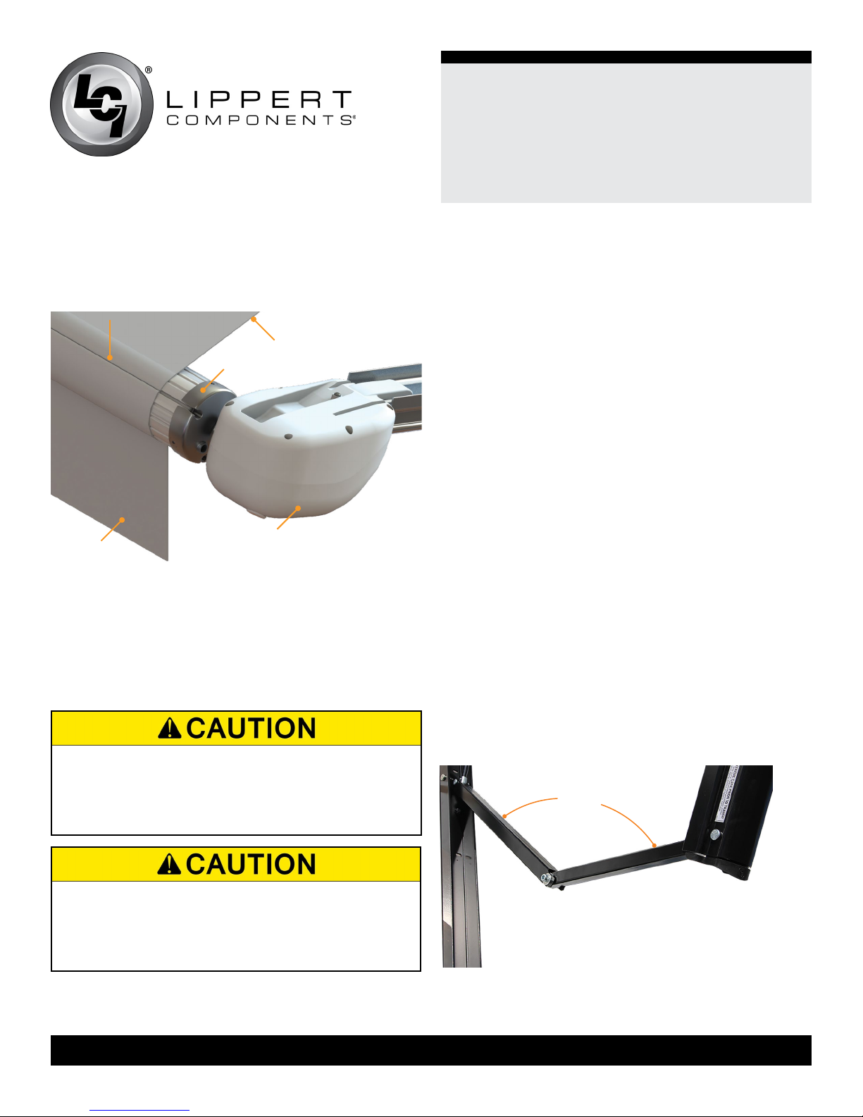
4. Use a screwdriver to spread open either end of the
awning rail channel on the installation side (Fig.4A).
5. To protect the fabric from damage during installation, le
any sharp edges or burrs from the awning rail channel.
6. Use silicone lubricant and spray the inside of the awning
rail channel (Fig.4B).
7. Remove the tape from the fabric. Unroll a small portion
of fabric.
NOTE: The next steps will require three people: One to
feed the polycord into the awning rail channel; two to walk
the support arm assemblies along the awning rail while the
fabric slides into position.
8. Slide the polycord into the awning rail channel and walk
the support arm assemblies and fabric down the awning
rail channel until the support arm assemblies are in line
with the previously-made centerline marks.
9. Lift the support arm assembly up and secure by setting
the awning assembly to the desired height and attaching it
to the side of the unit with two #14 x 1 ¼” screws at the top
(Fig.5) and two #14 x 1 ¼” screws at the bottom (Fig.6).
NOTE: Best practice for setting the awning height is to
push the top of the support arm assemblies up to be ush
with the bottom of the awning rail. The awning height
can be adjusted lower if desired, but make sure the
distance from the awning rail to the top of the support arm
assemblies is consistent at both ends of the awning.
NOTE: Make sure the awning assembly is square on the
unit prior to mounting the bottom two screws.
NOTE: Four rivets with ⁄” grip range can be used in
place of the two middle and two lower screws on laminated
walls.
A
B
Fig.4
Fig.5
Fig.6

7
lc i1.c om 574 - 5 37- 8 9 0 0 Rev:0 7.19 .18
Solera®
Power Awning 18V
Installation and Owner’s Manual
(For Aftermarket Applications)
CCD-0001260
10. Cut the cable ties, locate the switch on the side of the
arm and open the awning halfway out.
11. Remove the wire cover to expose the fastening points.
12. Install the remaining two #14 x 1 ¼” screws at any of
the three locations shown in the center of the support arm
(Fig.7).
13. Repeat this process for the other side of the awning
assembly.
Fig.7
possible
fastener
locations
Securing The Fabric
1. Extend and retract the awning several times to make
sure the fabric is square on the roll tube.
2. On both ends, secure the fabric in the awning rail no
more than 1” inside the edge of the fabric using a #6 x ½”
hex head screw (Fig.8).
3. Install the screw down through the awning rail into the
fabric and the polycord.
Fig.8
awning rail
fabric stitching
1”

8
lc i1.c om 574 - 5 37- 8 9 0 0 Rev:0 7.19 .18
Solera®
Power Awning 18V
Installation and Owner’s Manual
(For Aftermarket Applications)
CCD-0001260
Operation
Extending the Awning
1. Locate the locking latch on the side of the support arm, if
equipped, and unlock the latch.
NOTE: This latch is optional and may or may not be
installed on one or both support arms.
2. Lift up and hold the switch (Fig.11A) until the awning is
extended completely.
to battery
pack
to drive head
to charger
Charging the Battery
The battery for the Solera 18V Power Pack is located
inside the drive arm. The awning will operate 22-25 times
before needing to be recharged.
1. Locate the battery wires (Fig.9A) stored inside the
bottom of the drive arm. The wires will be afxed with a
hook-and-loop fastener.
2. Attach the battery wires to the included battery charger
cord (Fig.9B).
3. Plug the charger (Fig.10) into a 110V outlet.
4. When the battery is fully charged, a green light will
illuminate on the charger. A red light indicates the battery is
still charging.
A
B
A
extend
retract
Fig.9
Fig.10 Fig.11
9
lc i1.c om 574 - 5 37- 8 9 0 0 Rev:0 7.19 .18
Solera®
Power Awning 18V
Installation and Owner’s Manual
(For Aftermarket Applications)
CCD-0001260
Retracting the Awning
NOTE: The awning can be retracted without resetting the
pitch.
1. Hold the switch (Fig.11A) down until the awning is
retracted completely.
2. Locate the locking latch on the side of the support arm,
if equipped, and lock the latch.
NOTE: This latch is optional and may or may not be
installed on one or both support arms.
Adjusting Pitch
NOTE: The awning will pitch itself to purge the pooling of
excess water and may dump a signicant amount of water
without notice.
1. Pitch can be set by adjusting the pitch arm to tip one
side of the awning to allow water runoff or shade.
2. Extend the awning to the fully open position.
3. Choose the side of the awning for optimum shade or
convenient water runoff. Pull downward on the joint of
the pitch arm until desired pitch is set (Fig.13) to allow for
water runoff.
NOTE: Do not push the joint of the pitch arm up past
the point where the two sections are in line. This will put
tension on the gas strut, which can cause the strut to
break.
pitch
Extension is considered complete when the fabric is
completely unrolled, the valance is hanging down from the
roll tube and a section of the roll tube is exposed (Fig.12).
The awning fabric should always be above the roll tube.
However, if the extend switch is engaged too long or
extend is hit inadvertently, the awning will roll up backward.
This is not a defect. To correct the fabric orientation, set
the switch to retract (Fig.11A). The awning will then extend
to its correct orientation and normal operation can resume.
TYING DOWN THE ROLL TUBE ONCE THE AWNING
IS EXTENDED WILL NOT ALLOW THE FREE-
FLOATING SUPPORT ARMS TO WORK AS DESIGNED
AND MAY CAUSE DAMAGE TO THE AWNING OR
UNIT.
fabric polycord
fabric
roll tube
awning head
valance
Fig.12
Fig.13
DURING INCIDENTS OF HIGH WIND, HEAVY RAIN
OR EXTENDED TIME AWAY FROM THE UNIT,
IT IS ADVISABLE TO RETRACT THE AWNING
COMPLETELY TO PREVENT DAMAGE TO THE
AWNING AND THE UNIT.
10
lc i1.c om 574 - 5 37- 8 9 0 0 Rev:0 7.19 .18
Solera®
Power Awning 18V
Installation and Owner’s Manual
(For Aftermarket Applications)
CCD-0001260
NOTE: The awning can be retracted without resetting the
pitch.
NOTE: Belleville washers and bolts (Fig.14A) allow the
joint to remain in the position set by the operator. If the
pitch arm does not hold position, it can be tightened by
adjusting the bolt (Fig.14A) in the center of the pitch arm.
Troubleshooting
Manual Override
In the event of power loss or motor failure, the awning can
be extended and retracted manually. Perform the following
procedure to manually retract the awning.
NOTE: This procedure may also be performed to extend or
retract the awning in the event of dry camping or camping
without a battery.
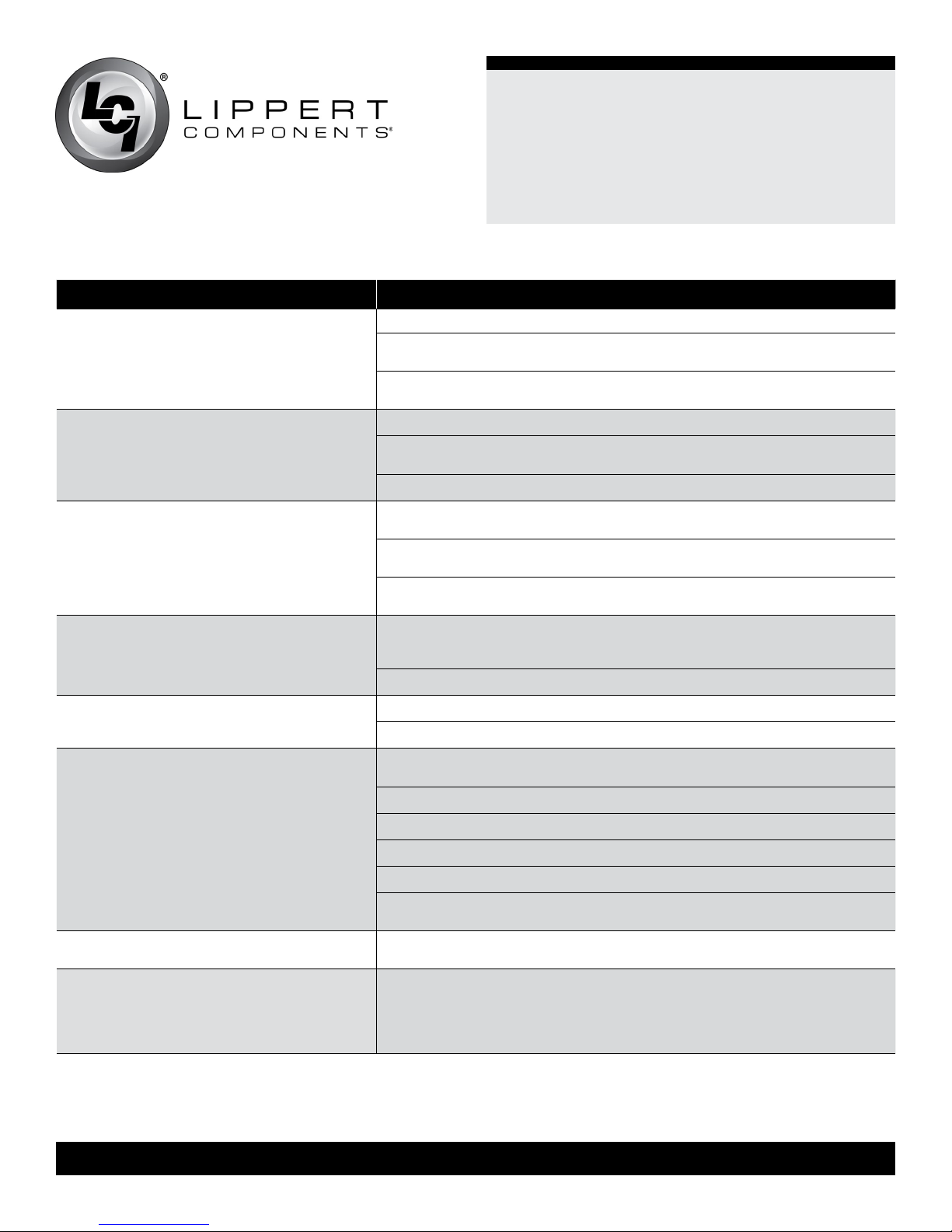
1. Remove the rubber grommet (Fig.15A) from the drive
head assembly, exposing the manual override nut on the
motor.
A
A
NOTE: The drive head assembly is always located on the
right side of the awning as it is viewed from outside of the
unit.
2. Using a ⁄” socket and cordless or electric drill or screw
gun, spin the manual override nut counterclockwise to
retract the awning (Fig.16).
Fig.14
Fig.15
Fig.16
NOTE: Use caution when retracting the awning manually.
The use of a step stool or ladder may be required to
completely retract the awning.
3. When the awning is completely retracted, replace the
rubber grommet in the drive head assembly (Fig.15A).
NOTE: The motor’s internal drive system prevents the
awning from moving (extend or retract) on its own. If the
motor is damaged or disabled, make sure to secure the
awning in the retracted position with a strap around both
the outer arm and the mount arm (Fig.17) before the
manual override nut is released.
Fig.17
11
lc i1.c om 574 - 5 37- 8 9 0 0 Rev:0 7.19 .18
Solera®
Power Awning 18V
Installation and Owner’s Manual
(For Aftermarket Applications)
CCD-0001260
What’s Happening What Should Be Done?
Awning won’t open or close.
If optional travel locks are installed, make sure that they have been unlocked.
Check for power at the motor when the switch is in the extended or retracted
position.
Check for secure plug connections in the arm between the battery and the
switch.
Awning pitch won’t stay in the at position.
Check for bad gas strut.
Check pitch arm bolt for proper tension. (High winds can cause the pitch arm
to deviate from the at position due to the built-in safety feature of the awning.)
Make sure all three washers are in the proper location of the pitch arm.
Awning doesn’t close all the way.
The awning is considered completely closed as long as the outer arm is
overlapping the mount arm. This overlap can vary.
Make sure there are no obstructions in the support arm assemblies preventing
the awning from closing.
Verify the fabric is square from unit to roll tube and is rolling up straight on the
roll tube.
Awning runs slow.
The awning will run slower during retract than extend. Retract is approximately
30 seconds while extend is approximately 20 seconds on a fully-charged
battery.
Make sure pitch arms are not bent in an upward direction.
Lights won’t work.
There is a resettable fuse that can take up to 30 seconds to reset.
Make sure to have 12V DC to the red wire on the light.
Awning seems to wobble when extending or
retracting.
Make sure the bolts that hold the head to the support arm assemblies are
tight.
Make sure end caps are seated properly on the roll tube.
Make sure the shaft coming out of the head going to the end cap isn’t bent.
Make sure the wall mount is properly secured to the wall.
Make sure no part of the support arm assemblies are bent.
Make sure the wear collar spacers are all properly located in the support arm
assemblies.
Awning works in opposite direction of what
switch shows.
Wires going to awning have been reversed or switched. Reverse the wires.
Awning rolls up backward
The awning fabric should always be above the roll tube. However, if the extend
switch is engaged too long or extend is hit inadvertently instead of retract,
the awning will roll up backward. This is not a defect. To correct the fabric
orientation, press the retract button. The awning will then extend to its correct
orientation and normal operation can resume.
Solera Power Awning Troubleshooting

12
lc i1.c om 574 - 5 37- 8 9 0 0 Rev:0 7.19 .18
Solera®
Power Awning 18V
Installation and Owner’s Manual
(For Aftermarket Applications)
CCD-0001260
Maintenance - Solera Awnings
Fabric Care
If the awning is retracted while wet, extend the awning
and let it dry as soon as conditions allow before again
retracting. This will help prevent the formation of mildew
and add to the life of the awning.
NOTE: Mildew does not form on the fabric itself, but on the
accumulated dust, dirt and grime.
Periodically clean vinyl or woven acrylic fabric using a
mixture of ¼ cup of dish soap and ve gallons of warm
water.
1. Liberally apply the mixture on the top of the fabric and
retract the awning for ve minutes. This will apply the
mixture to the bottom of the fabric as well.
2. Extend the awning and hose off with fresh water.
3. Repeat if necessary.
4. Allow to dry before retracting.
Notes
Manual information may be distributed as a complete
document only, unless Lippert Components provides
explicit consent to distribute individual parts.
All manual information is subject to change without
notice. Revised editions will be available for free
download at lci1.com. Manual information is considered
factual until made obsolete by a revised version.
Please recycle all obsolete materials and contact
Lippert Components with concerns or questions.
This manual suits for next models
1
Table of contents
Other Solera Accessories manuals


