Valcom V-9956 User manual
Issue 4
1947208
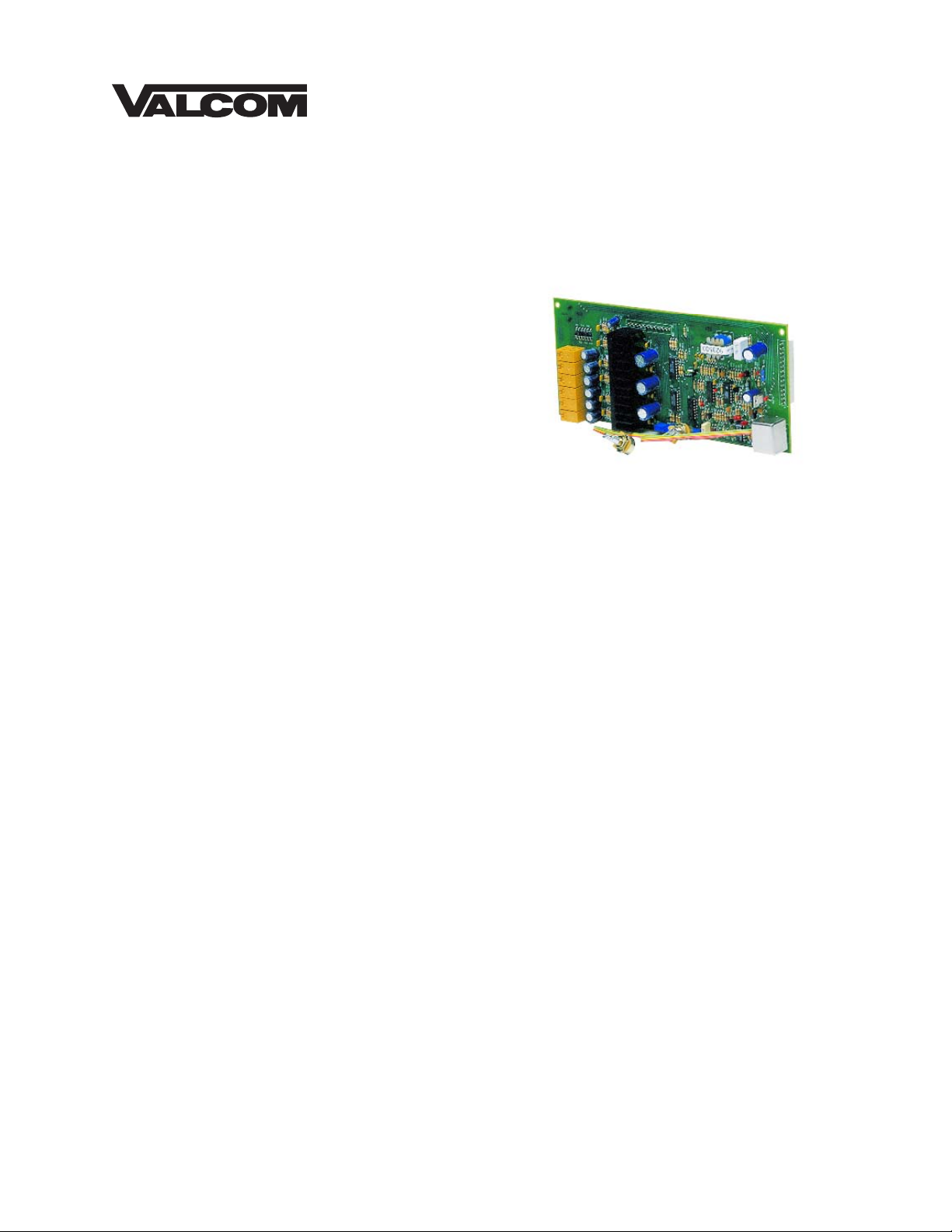
V-9956
HANDSFREE TALKBACK PLUG-IN BOARD
INTRODUCTION
The V-9956 Handsfree Talkback Plug-In Board,
designed to be used with the V-2006A, allows
the V-2006A to be converted to a V-2006AHF to
permit handsfree operation.
These instructions contain the specifications and
information necessary to install and operate the
V-9956 used in conjunction with the V-2006A.
DIMENSIONS/WEIGHT
•9.8” H x 4.5” W x 1.75” D
(24.89cm H x 11.43cm W x 4.44cm D)
•1.5 lbs (0.68 kg)
CONNECTIONS
The V-9956 can be purchased as an "add on"
feature after the initial purchase of a V-2006A.
By adding a V-9956 Handsfree Talkback Plug-In
Board, the V-2006A unit can be modified to a
V-2006AHF.
The V-2006AHF is programmable on a per zone
basis for one-way or talkback communication.
When using talkback speakers, the zone must
be programmed for talkback communication. A
single zone may have both one-way or talkback
speakers. One-way amplified speakers should
be connected to the low-level outputs for zone 1
(W-S pair), zone 2 (R-O pair), zone 3 (R-BR
pair), zone 4 (BK-BL pair), zone 5 (BK-G pair)
and zone 6 (BK-S pair). These speakers will act
as one-way speakers for its associated zone
whether or not the zone is programmed for
one-way or talkback paging. If 45 Ohm speakers
are connected to the handsfree output and the
zone is programmed for one-way, the speakers
will receive the page. The page volume control
located on the V-9956 board regulates the
volume of the 45 Ohm talkback speakers under
these circumstances and also provides volume
adjustment of talkback speakers during group
call. The All Call volume adjustment controls the
volume of talkback speakers during all call.
When using Talkback speakers, the zone must be
programmed for Talkback communication.
Do not connect amplified speakers to the V-9956
talkback zones as they are already amplified.
__ 1. Unplug the V-2006A from the AC power
source; unplug the battery backup if one
is used.
__ 2. Remove the cover of the V-2006A unit
by first removing the 6-32 screws that
attach the cover to the base.
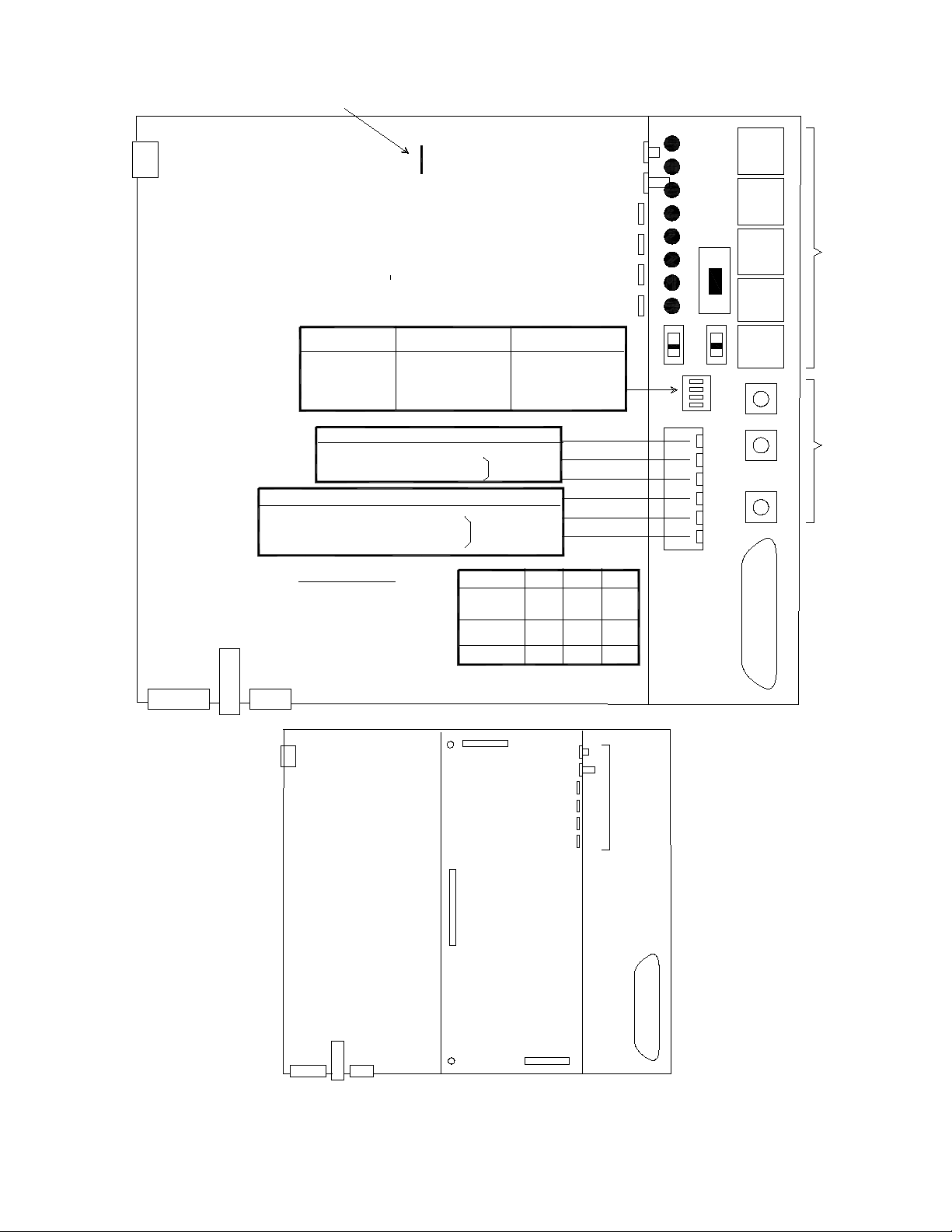
__ 3. Remove the jumper on the V-2006A to
allow handsfree operation. Refer to
Figure 1 for location of the jumper.
__ 4. Plug the V-9956 board into the chassis
of the V-2006A as shown in Figure 2.
Insure the proper alignment of all pins
for proper fit and operation.
__ 5. Secure the V-9956 board to the
V-2006A chassis using the two (2)
screws and washers provided.
__ 6. Insert the Phone to Speaker and
Speaker to Phone volume controls into
the cover of the V-2006A as shown in
Figure 2. The control with the long shaft
is Phone to Speaker; the control with the
shorter shaft is Speaker to Phone.
Secure these controls with the washers
and nuts provided.
__ 7. Replace the cover of the V-2006A unit,
insert the 6-32 screws and tighten
snugly to hold in place.
__ 8. Affix the enclosed label to the side of the
V-2006A unit to make certain the
controls relative to the V-9956 are
identified.
2947208
__ 9. Using twisted pair telephone wire,
connect the talkback speakers to the
appropriate output (see Figure 3) on the
V-2006A connection block. Zone 1
speakers connect to the Y-O pair, Zone
2 speakers connect to the Y-G pair,
Zone 3 speakers connect to the Y-BR
pair, Zone 4 speakers connect to the
Y-S pair, Zone 5 speakers connect to
the V-BL pair, and Zone 6 speakers to
the V-O pair. No more than two (2) 45
Ohm speakers should be connected to
any talkback zone.
Do not use 8 Ohm speakers.
__ 10. Restore power to the V-2006A, access
page and adjust the volume controls as
required. There are separate volume
controls for the Phone to Speaker,
Speaker to Phone, Page, All Call,
Background Music and Tone Signaling.
For best results, the Speaker to Phone
volume control should be turned as low
as possible to where background music
is just barely audible.
__ 11. When using talkback speakers, the zone
must be programmed for talkback
communication. Refer to the V-2006A
VSP for programming instructions.
TECHNICAL ASSISTANCE
When trouble is reported, verify that power is
being supplied to the unit and there are no
broken connections. Check voltages for proper
polarity on the crossconnect block. If a spare
unit is available, substitute that unit for the
suspected defective unit.
Assistance in troubleshooting is available from
the factory. When calling, you should have a
VOM, several clip leads, a telephone test set
available and call from the job site. Call (540)
563-2000 and press 1 for Technical Support or
visit our website at http://www.valcom.com.
The V-9956 contains no user serviceable parts
and is not field repairable. A service facility is
maintained in Roanoke, VA. Should repairs be
necessary, attach a tag to the unit clearly stating
your company name, address, phone number,
contact person and the nature of the problem.
Send the unit to:
Valcom, Inc.
Repair and Return Dept
5614 Hollins Road
Roanoke, VA 24019-5056
VALCOM LIMITED WARRANTY
Valcom, Inc. warrants its products to be free from defects in materials and workmanship under conditions of normal use and service
for a period of one year from the date of shipment. The obligation under this warranty shall be limited to the replacement, repair or
refund of any such defective device within the warranty period, provided that:
1. inspection by Valcom, Inc. indicates the validity of the claim;
2. the defect is not the result of damage, misuse, or negligence after the original shipment;
3. the product has not been altered in any way or repaired by others and that factory sealed units are unopened (a service
charge plus parts and labor will be applied to units defaced or physically damaged);
4. freight charges for the return of products to Valcom are prepaid;
5. all units ‘out of warranty’ are subject to a service charge. The service charge will cover minor repairs (major repairs will
be subject to additional charges for parts and labor).
This warranty is in lieu of and excludes all other warranties, expressed or implied and in no event shall Valcom, Inc. be
liable for any anticipated profits, consequential damages, loss of time or other losses incurred by the buyer in connection
with the purchase, operation, or use of the product.
This warranty specifically excludes damage incurred in shipment. In the event a product is received in damaged condition, the
carrier should be notified immediately. Claims for such damage should be filed with the carrier involved in accordance with the
F.O.B. point.
Headquarters: In Canada
Valcom, Inc. CMX Corporation
5614 Hollins road 35 Van Kirk Drive #11 and 12
Roanoke, VA 24019-5056 Brampton, Ontario L7A 1A5
Phone: (540) 563-2000 Phone: (905) 456-1072
FAX: (540) 362-9800 FAX: (905) 456-2269
3947208
D1
D2
D3
D4
D5
D6
D7
D8
SW6
All Call 2
J7
All Call 1
J9
Program
J6
Override
J5
System
J4
R91
R92
Tones
All Call
R90
Music
J1
MALE
AMPHENOL
CONNECTOR
4
3
2
1
P12
SW2
SW1
VOLUMECONTROLSRJ11's
ON
OFF
Loop Loop
This side of the V-2006A/V-2006AHF oriented toward floor.
Voltage
Select
Switch
AC Connector
Fuse
Battery
Backup Molex
Connector
Spkr/Phone
Phone/Spkr
Page
Music
Tones
All Call
VolumeControls
for the
V-2006AHF
Slide Switches
SW1 - Ground Start or Loop Start
Trunk for Override Feature
SW2 - Ground Start or Loop Start
Trunk Access
SW6 - Battery Feed (ON/OFF)
Switch SW1 SW2 SW6
Loop Start
Trunk C.O.
Down Down Up
Ground Start
Trunk
Page Port
Up Up Up
--- --- Down
For Remote Door Unlock
K5 NC Break
K5 NO Make
K5 COM Stationary
Customer Provided
Electric Strikeplate
Solenoid
Zone 6 Auxiliary (Contact Closure)
K6 NC
K6 NO
K6 COM Mute
Ground Ground
K6 COM
K6 NC
K6 NO
K5 COM
K5 NC
K5 NO
D1 - Handsfree or One-Way
D2 - Background Music
D3 - Night Ring
D4 - Time Clock Tone
D5 - Group 1
D6 - Group 2
D7 - Group 3
D 8 - All Call Group
Programming Status LEDs
SW3 DIP
SWITCH OPTIONS
1
OFF (UP)
(Away from Board)
ON (DOWN)
(Toward Board)
Dial Tone No Dial Tone
* 2 Alert Tone/Ringback Tone No Alert Tone
* 3 Repeated Alert Tone No RepeatedAlert Tone
4Not Used Not Used
SW3
DOWN
UP
Normally Open
Normally Closed
Common
Normally Open
Normally Closed
Common
K6 relay operates
whenever zone 6
is in use
K5 relay operates for
2.2 seconds when the *
is pressed when
any zone accessed
K6 Relay
K5 Relay
It is necessary to remove the JUMPER on the V-2006A board before connecting the V-9956 board to the V-2006A board.
Spkr/Phone
Phone/Spkr
Page
Music
Tones
All Call
Volume
Controls
with a
V-9956
added
J1
MALE
AMPHENOL
CONNECTOR
FIGURE 1
FIGURE 2
V-9956 Board

4947208
26
1
27
2
28
3
29
4
30
5
31
6
32
7
33
8
34
9
35
10
36
11
37
12
38
13
39
14
40
15
41
16
42
17
43
18
44
19
45
20
46
21
47
22
48
23
49
24
50
25
W/BL
BL/W
W/O
O/W
W/GR
GR/W
W/BR
BR/W
W/S
S/W
R/BL
BL/R
R/O
O/R
R/G
G/R
R/BR
BR/R
R/S
S/R
BK/BL
BL/BK
BK/O
O/BK
BK/G
G/BK
BK/BR
BR/BK
BK/S
S/BK
Y/BL
BL/Y
Y/O
O/Y
Y/G
G/Y
Y/BR
BR/Y
Y/S
S/Y
V/BL
BL/V
V/O
O/V
V/G
G/V
V/BR
BR/V
V/S
S/V
ABC DEF
FIGURE 3
66 BLOCK CONNECTIONS FOR T E V-9956
System Tip
System Ring
Override Tip
Override Ring
Music Input
Music Input
Page Port Contact Closure
Inhibit
Zone 1 - Low Level Output Tip
Zone 1 - Low Level Output Ring
-24V out
GND Out
Zone 2 - Low Level Output Tip
Zone 2 - Low Level output Ring
-24V Out
GND Out
Zone 3 - Low Level Output Tip
Zone 3 - Low Level Output Ring
-24V Out
GND Out
Zone 4 - Low Level Output Tip
Zone 4 - Low Level Output Ring
-24V Out
GND Out
Zone 5 - Low Level Output Tip
Zone 5 - Low Level Output Ring
-24V Out
GND Out
Zone 6 - Low Level Output Tip
Zone 6 - Low Level Output Ring
-24V Out
GND Out
Zone 1 - andsfree Output Tip
Zone 1 - andsfree Output Ring
Zone 2 - andsfree Output Tip
Zone 2 - andsfree Output Ring
Zone 3 - andsfree Output Tip
Zone 3 - andsfree Output Ring
Zone 4 - andsfree Output Tip
Zone 4 - andsfree Output Ring
Zone 5 - andsfree Output Tip
Zone 5 - andsfree Output Ring
Zone 6 - andsfree Output Tip
Zone 6 - andsfree Output Ring
Clock Closure
Clock Closure
UNA Closure
UNA Closure
UNA Ringing
UNA Ringing
Used with the V-9956 Installed
Other Valcom Accessories manuals


