HYTROL ProSort 431 Manual

Effective April 2015
(Supercedes October 2005)
Bulletin #676
Installation
and
Maintenance
Manual
with Safety Information
and Parts List
RECOMMENDED SPARE PARTS HIGHLIGHTED IN GRAY
ProSort 400 Elite
Manual
de Instalación
y
Mantenimiento
con Información sobre Seguridad
y Lista de Refacciones
LAS REFACCIONES RECOMENDADAS SE RESALTAN EN GRIS
© COPYRIGHT 2015–HYTROL CONVEYOR CO., INC.
IMPORTANT!
DO NOT DESTROY
¡IMPORTANTE!
NO DESTRUIR
Hytrol Conveyor Co., Inc. Jonesboro, Arkansas
PRESS OPTIMIZED FOR THE ENVIRONMENT
(ImpresIón OptImIzada para prOteger el medIO ambIente)
(
_____
)

TABLE OF CONTENTS
INTRODUCTION
Receiving and Uncrating....................2
How to Order Replacement Parts.............2
SAFETY INFORMATION................3
INSTALLATION
Location.................................4
Conveyor Set-Up........................4,5
Electrical Equipment .....................5, 6
OPERATION
Conveyor Start-Up.........................6
MAINTENANCE
Lubrication...............................6
Controlling the ProSort .................6, 7, 8
Pneumatic Divert Switch Checklist ..........8, 9
Electric Divert Switch Checklist...............9
Carrying Chain Installation ...............9, 10
Install Guard Rails at Divert Locations ........10
Locating the Spurs .......................10
Pneumatic Divert Switch Removal Procedure ..10
Electric Divert Switch Removal Procedure .....11
Electric Switch Homing Procedure ...........11
Trouble Shooting.........................11
Maintenance Checklist ............Back Cover
REPLACEMENT PARTS
ProSort 421 Parts Drawings
Catenary Divert and Drive Section ...........12
Intermediate and Return Divert Section .......13
Tail and Divert Section ....................14
Induction Unit............................15
ProSort 421 Parts List.............. 15, 16, 17
ProSort 431 Parts Drawings
Catenary Divert and Drive Section ...........18
Intermediate and Return Divert Section .......19
Tail and Divert Section ....................20
Induction Unit............................21
ProSort 431 Parts List.............. 21, 22, 23
Pneumatic Divert Switch Assembly
Parts Drawing & List ......................24
Electric Divert Switch Assembly
Parts Drawing & List ......................24
Safety Switch Assembly Parts Drawing & List ..25
Spanish Version ..................26
INTRODUCTION
This manual provides guidelines and procedures for installing,
operating, and maintaining your conveyor. A complete parts list
is provided with recommended spare parts highlighted in gray.
Important safety information is also provided throughout the manual.
For safety to personnel and for proper operation of your conveyor, it
is recommended that you read and follow the instructions provided
in this manual.
• Receiving and Uncrating
1. Check the number of items received against the bill of lading.
2. Examine condition of equipment to determine if any damage
occurred during shipment.
3. Move all crates to area of installation.
4. Remove crating and check for optional equipment that may be
fastened to the conveyor. Make sure these parts (or any foreign
pieces) are removed.
• How to Order Replacement Parts
Includedinthismanual arepartsdrawings withcompletereplacement
parts lists. Minor fasteners, such as nuts and bolts, are not
included.
When ordering replacement parts:
1. Contact Dealer from whom conveyor was purchased or nearest
HYTROL Integration Partner.
2. Give Conveyor Model Number and Serial Number or HYTROL
Factory Order Number.
3. Give Part Number and complete description from Parts List.
4. Give type of drive. Example—8” End Drive, 8” Center Drive, etc.
5. If you are in a breakdown situation, tell us.
HYTROL Serial Number
(Located near Drive on Powered Models).
NOTE: If damage has occurred or freight is missing,
Contact your Hytrol Integration Partner.
JONESBORO, ARKANSAS
Model
XX
Hytrol Conveyor
Company, Inc.
SERIAL # 123456
Model
2
[)={]~[f@~ ~@ITi)W@W@[f
~@[ITffi~~ITi)w9
~ITi)@c

SAFETY INFORMATION
• Installation
GUARDS AND GUARDING
Interfacing of Equipment. When two or more pieces of equipment are
interfaced, special attention shall be given to the interfaced area to
insure the presence of adequate guarding and safety devices.
Guarding Exceptions. Whenever conditions prevail that would require
guarding under these standards, but such guarding would render the
conveyor unusable, prominent warning means shall be provided in
the area or on the equipment in lieu of guarding.
Guarded by Location or Position. Where necessary for the protection
of employees from hazards, all exposed moving machinery parts
that present a hazard to employees at their work station shall be
mechanically or electrically guarded, or guarded by location or
position.
Remoteness from frequent presence of public or employed• personnel shall constitute guarding by location.
When a conveyor passes over a walkway, roadway, or work• station, it is considered guarded solely by location or position if all
movingpartsareatleast8ft.(2.44m)abovetheoororwalking
surface or are otherwise located so that the employee cannot
inadvertently come in contact with hazardous moving parts.
Although overhead conveyors may be guarded by location, spill• guards, pan guards, or equivalent shall be provided if the product
may fall off the conveyor for any reason and if personnel would
be endangered.
HEADROOM
When conveyors are installed above exit passageways, aisles,• or corridors, there shall be provided a minimum clearance of 6
ft.8in.(2.032m)measuredverticallyfromtheoororwalking
surface to the lowest part of the conveyor or guards.
Wheresystem function willbe impaired byprovidingthe minimum• clearanceof 6ft.8in.(2.032m)through anemergencyclearance,
alternate passageways shall be provided.
It is permissible to allow passage under conveyors with less•
than6ft.8in.(2.032m)clearancefromtheoorforotherthan
emergency exits if a suitable warning indicates low headroom.
• Operation
A) Only trained employees shall be permitted to operate conveyors.
Training shall include instruction in operation under normal conditions
and emergency situations.
B) Where employee safety is dependent upon stopping and/or
starting devices, they shall be kept free of obstructions to permit
ready access.
C) The area around loading and unloading points shall be kept clear
of obstructions which could endanger personnel.
D) No person shall ride the load-carrying element of a conveyor
underanycircumstancesunlessthatpersonisspecicallyauthorized
by the owner or employer to do so. Under those circumstances, such
employee shall only ride a conveyor which incorporates within its
supportingstructureplatformsorcontrolstationsspecicallydesigned
for carrying personnel. Under no circumstances shall any person ride
on any element of a vertical conveyor.
E) Personnel working on or near a conveyor shall be instructed as to
the location and operation of pertinent stopping devices.
F) A conveyor shall be used to transport only material it is capable
of handling safely.
G) Under no circumstances shall the safety characteristics of the
conveyor be altered if such alterations would endanger personnel.
H) Routine inspections and preventive and corrective maintenance
programs shall be conducted to insure that all safety features and
devices are retained and function properly.
I) Personnelshould bealertedtothepotential hazardof entanglement
in conveyors caused by items such as long hair, loose clothing, and
jewelry.
J) Conveyors shall not be maintained or serviced while in operation
unless proper maintenance or service requires the conveyor to be in
motion. In this case, personnel shall be made aware of the hazards
and how the task may be safely accomplished.
K)Ownersofconveyorshouldinsurepropersafetylabelsareafxed
to the conveyor warning of particular hazards involved in operation of
their conveyors.
• Maintenance
All maintenance, including lubrication and adjustments, shall be•
performedonlybyqualiedandtrainedpersonnel.
It is important that a maintenance program be established to• insurethatallconveyorcomponentsaremaintainedinacondition
which does not constitute a hazard to personnel.
When a conveyor is stopped for maintenance purposes, starting• devices or powered accessories shall be locked or tagged out
in accordance with a formalized procedure designed to protect
all persons or groups involved with the conveyor against an
unexpected start.
Replace all safety devices and guards before starting equipment• for normal operation.
Whenever practical, DO NOT lubricate conveyors while they are• in motion. Only trained personnel who are aware of the hazard
of the conveyor in motion shall be allowed to lubricate.
Safety Guards
Maintain all guards and safety devices IN POSITION and IN SAFE
REPAIR.
Safety Labels
In an effort to reduce the possibility of injury to personnel working
around HYTROL conveying equipment, safety labels are placed at
various points on the equipment to alert them of potential hazards.
Please check equipment and note all safety labels. Make certain
your personnel are alerted to and obey these warnings. See Safety
Manual for examples of warning labels.
CAUTION! Because of the many moving parts on the conveyor, all
personnel in the area of the conveyor need to be warned that the conveyor
is about to be started.
REMEMBER Do not remove, reuse or modify material handling equipment
for any purpose other than it’s original intended use.
3

INSTALLATION
• Location
1. Determine
direction of product
flow. Figure 4A
indicates the flow as
related to the drive.
2. Refer to “Match-
Mark” numbers on
ends of conveyor
sections. (Figure 4A).
Position them in this
sequence near area
of installation.
• Conveyor Set-Up
1. Mark a chalk line on floor to locate center of the conveyor.
2. Attach supports and vibration pads to all conveyor sections shown in Figures 4A and 4B.
Adjust elevation to required height. Hand tighten bolts only at this time.
3. During installation, check to make sure each bed section is square. Measure the diagonals
from corner to corner of the frame. If they are not equal the frame must be squared. Attach
a come-along or some other suitable pulling device across longest corners and pull until the
section is square.
4. Place the infeed (tail) section in position. Locate the (2) provided threaded rods (on the
infeed or discharge end). Use these rods to pull together each section during installation.
5. Install remaining sections, placing end without support on extended pivot plate of previous
section (Figure 4A).
6. Fasten sections together with splice plates and pivot plates. (Figure 4B). Hand tighten bolts
only at this time.
7. Check to see that conveyor is level across the width and length of unit. Adjust supports
as necessary.
8. After all sections have been squared and levelled, tighten all splice channels and support
mounting bolts and lag support to the floor.
9. Check alignment of wearstrip at all section joints. Sand wearstrip as necessary to provide
a smooth wear surface (Figure 4B).
10. Starting on the infeed end, fasten bearing profile to wearstrip guide using rubber mallet to
force the profile edge under the wearstrip (Figure 4B). Glue infeed end of profile to the support
angle with loctite # 401 or 454 adhesive.
11. Fasten 1/2” main air line to bottom of conveyor channel with cable ties (Figures 4D & 5C).
Connect 3/8”air lines at divert switches as shown in Figures 5A & 5B.
12. Connect main air line to the Filter/Regulator, (Figure 5C) Set regulator to working pressure
of 60 P.S.I. Install low pressure switch, at farthest point from regulator (Figure 5A).
13. Install electrical controls and wire motor. Verify correct motor rotation at this time. See
Page 5 & 6 for electrical control information.
14. Check each divert switch to see that it is operating properly. This must be done before
carrying chains are installed. See instructions on Page 9 & 10.
15. Check proximity switch clearance at each internal safety switch (Figure 5E). Adjust if
necessary.
16. Install carrying chains per instructions on Page 9 & 10.
17. Adjust pop-up roller assembly at discharge end to optimize transition of packages from the
ProSort to the take away conveyor. Set pop-up roller proximity switch per Figure 5D.
18. Install chain oiler at infeed and connect to oil lines as shown in Figure 5F. Refer to the
Lubrication section, page 6, for type of oil required. After mounting, the oiler will need to be
adjusted for proper oiling of mounting chains. Adjustment may be made using a combination
of solenoid activation time and flow adjustment screws. (A good rule of thumb for solenoid
adjustment is to turn the oiler on for one complete chain revolution for every 2 hours of sorter
operation.) Typically, the chain on the divert side will need slightly more oil; the flow adjustment
screws can be altered to achieve volume. CAUTION: Do not allow oil to drip on floor.
19. Locate spurs per instructions on Page 10.
20. Remove threaded rods before start-up.
CONVEYOR
ITEM TO
HYTROL CONVEYOR CO. INC.
JONESBORO, AR
A
12
CONVEYOR
ITEM TO
HYTROL CONVEYOR CO. INC.
JONESBORO, AR
A
21
DRIVE
(UNIDAD MOTRIZ)
CANTENARY DIVERT
(DESVIADOR-CATENARIA)
RETURN DIVERT
FLOW
(DESVIADOR-RETORNO)
TAIL
(COLA)
DIVERT
(DESVIADOR)
INDUCTION BELT
DRIVE
(BANDA
INDUCCION
MOTRIZ)
INDUCTION BELT
LENGTH
(LONGITUD DE LA BANDA DE INDUCCION)
"MATCH-MARK NUMBERS"
(ETIQUETAS DE SECUENCIA DE ARMADO)
DRIVE SUPPORT
(SOPORTE MOTRIZ)
KNEE BRACE
(SOPORTE ANGULAR)
INTERMEDIATE
SUPPORTS
(SOPORTES INTERMEDIOS)
ADJUST TO DESIRED
ELEVATION
(AJUSTE A LA ALTURA
DESEADA)
(FLUJO)
INTERMEDIATE
(NTERMEDIO)
INDUCTION SUPPORT
(SOPORTE INDUCCION)
SORTER
(TRANSPORTADOR)
FIGURE 4A
THREADED RODS
(VARILLAS DE ROSCA)
FIGURE 4B
FIGURE 5D FIGURE 4B FIGURE 4C FIGURE 5F
FIGURE 5C FIGURE 5B FIGURE 5A FIGURE 5E
FIGURE 4D
WEARSTRIP CHAIN
GUIDE DETAIL
SECTION JOINT
(UnIOn de seCCIOnes)
BEARING PROFILE
(perFIl del
rOdamIentO)
CONVEYOR CHANNEL
(Canal del transpOrtadOr)
WEARSTRIP CHAIN GUIDE
(gUIa de Cadena)
CHAIN GUIDES MUST BE
EVEN AT JOINT
(las gUIas de Cadena
deben ser UnIFOrmes
en la UnIOn)
FIGURE 4C
4
,
I
I
' '
• *
•
--
' ' '
{
BED
SPACER
(ESPACIADOR
DE
GAMA)
.
.
SPLICE
CHANNEL
(CANAL
EMPALME)

1/2" TEE
(te de 1/2")
MAIN AIR
(lInea prInCIpal
de aIre)
3/8" TO 1/4" REDUCER
(redUCtOr de 3/8"a 1/4")
LINE TO VALVE
(lIneaa ValVUla)
1/2" TO 3/8" REDUCER
(redUCtOr de 1/2"a 3/8")
PRESSURE SWITCH
PRESET AT 48 PSI
(InterrUptOr de
presIOn aJUstadO
a 48 psI)
END SWITCH
(InterrUptOr
eXtremO)
FIGURE 5A
3/8" LINE
(lInea de 3/8")
1/2" to 3/8" REDUCER
(redUCtOr de 1/2"a 3/8")
1/2" TEE
(te de 1/2")
1/2" MAIN LINE
(lInea prInCIpal de 1/2")
3/8" FEMALE TO 3/8" MALE
QUICK CONNECT FITTING
PLUG INTO VALVE
(Hembra de 3/8" a maCHO de 3/8"
de rapIda COneXIOn a ValVUla)
INTERMEDIATE
SWITCHES
(InterrUptOres
IntermedIOs)
FIGURE 5B
AIR SUPPLY TO
AIR VALVES
(SUMINISTRO D
E
AIRE A LAS
VALVULAS)
1/2" UNION TEE
(UNION TE DE 1/2")
BOWL GUARD
(TAZON PROTECTOR)
FILTER/REGULATOR
(REGULADOR/FILTRO)
GAUGE
(MEDIDOR)
MAIN AIR
SUPPLY
LINE
(SUMINISTRO
PRINCIPAL
DE AIRE)
MOUNTING BRACKET
(FASTEN TO
CONVEYOR CHANNEL)
(PLACA DE MONTAJE
[SUJETAR AL CANAL
DEL TRANSPORTADOR])
LOCK-OUT VALVE
(VÁLVULA DE BLOQUEO)
FIGURE 5C
1/4" FROM PROX
TO TUBE
(1/4” DEL INTERRUPTOR
DE PROXIMIDAD AL
TUBO)
FIGURE 5D
FLOW
(FlUJO)
PROXIMITY SWITCH
(InterrUptOr de
prOXImIdad)
SWITCH SENSOR
(sensOr del InterrUptOr) (3/16" del Frente del prOX
a la plaCa de metal)
3/16" FROM PROX FACE
TO METAL PLATE
SPUR SIDESWITCH SIDE
(ladO del
InterrUptOr) (ladO de la espUela)
FIGURE 5E
• Electrical Equipment
CONTROLS
Electrical Code: All motor controls and wiring shall conform to the National
Electrical Code (Article 670 or other applicable articles) as published by the
National Fire Protection Association and as approved by the American Standards
Institute, Inc.
CONTROL STATIONS
A) Control stations should be so arranged and located that the operation of the
equipment is visible from them, and shall be clearly marked or labeled to indicate
the function controlled.
B) A conveyor which would cause injury when started shall not be started until
employees in the area are alerted by a signal or by a designated person that the
conveyor is about to start.
When a conveyor would cause injury when started and is automatically
controlled or must be controlled from a remote location, an audible device shall
be provided which can be clearly heard at all points along the conveyor where
personnel may be present. The warning device shall be actuated by the controller
device starting the conveyor and shall continue for a required period of time
before the conveyor starts. A flashing light or similar visual warning may be used
in conjunction with or in place of the audible device if more effective in particular
circumstances.
Where system function
would be seriously hindered
or adversely affected by the
required time delay or where
the intent of the warning may
be misinterpreted (i.e., a work area with many different conveyors and allied
devices), clear, concise, and legible warning shall be provided. The warning shall
indicate that conveyors and allied equipment may be started at any time, that
danger exists, and that personnel must keep clear. The warnings shall be provided
along the conveyor at areas not guarded by position or location.
C) Remotely and automatically controlled conveyors, and conveyors where
operator stations are not manned or are beyond voice and visual contact from drive
areas, loading areas, transfer points, and other potentially hazardous locations on
the conveyor path not guarded by location, position, or guards, shall be furnished
with emergency stop buttons, pull cords, limit switches, or similar emergency stop
devices.
All such emergency stop devices shall be easily identifiable in the immediate
vicinity of such locations unless guarded by location, position, or guards. Where
the design, function, and operation of such conveyor clearly is not hazardous to
personnel, an emergency stop device is not required.
The emergency stop device shall act directly on the control of the conveyor
concerned and shall not depend on the stopping of any other equipment. The
emergency stop devices shall be installed so that they cannot be overridden from
other locations.
D) Inactive and unused actuators, controllers, and wiring should be removed from
WARNING!Electricalcontrolsshallbeinstalledandwiredbyaqualiedelectrician.Wir-
ing information for the motor and controls are furnished by the equipment manufacturer.
OIL CUP
(reCIpIente
de aCeIte)
ADJUSTMENT
SCREWS
(tOrnIllOs
de aJUste)
OIL LINES
TO BRUSHES
(lIneas de
aCeIte a
brOCHas)
FIGURE 5F
5
-
__
,,.....------
........
__
_,,,,-----
//
"-,\
__
(
! '(
( i
\ /
\ /
-.....___
//
---....
______
,,.....--
------
.....
____
......
----------
....
0 0 )
(

control stations and panel boards, together with obsolete diagrams, indicators,
control labels, and other material which serve to confuse the operator.
SAFETY DEVICES
A) All safety devices, including wiring of electrical safety devices, shall be
arranged to operate in a “Fail-Safe” manner, that is, if power failure or failure of the
device itself would occur, a hazardous condition must not result.
B) Emergency Stops and Restarts. Conveyor controls shall be so arranged
that, in case of emergency stop, manual reset or start at the location where the
emergency stop was initiated, shall be required of the conveyor(s) and associated
equipment to resume operation.
C) Before restarting a conveyor which has been stopped because of an
emergency, an inspection of the conveyor shall be made and the cause of the
stoppage determined. The starting device shall be locked out before any attempt
is made to remove the cause of stoppage, unless operation is necessary to
determine the cause or to safely remove the stoppage.
Refer to ANSI Z244.1-1982, American National Standard for Personnel Protection
– Lockout/Tagout of Energy Sources – Minimum Safety Requirements and OSHA
Standard Number 29 CFR 1910.147 “The Control of Hazardous Energy (Lockout/
Tagout).”
OPERATION
• Conveyor Start-Up
Before conveyor is turned on, check for foreign objects that may have been left
inside conveyor during installation. These objects could cause serious damage
during start-up.
After conveyor has been turned on and is operating, check all moving parts to
make sure they are working freely.
MAINTENANCE
• Lubrication
BEARINGS
A) NO GREASE FITTING - Prelubricated - No lubrication required.
B) WITH GREASE FITTING - Relubricate approximately every 10 to 12 weeks with
lithium base grease suitable for ball bearing service.
RECOMMENDED CHAIN LUBRICANT
A good grade of clean non-
detergent petroleum or synthetic
oil is recommended. See chart
for proper viscosity.
REDUCERS
See recommendations by manufacturer.
• Controlling the ProSort
A good software package is essential for the proper operation of the ProSort
sorter. With proper controls, the sorter will provide accurate, efficient, reliable
sorting for many years. Inadequate controls, however, may result in poor
sorter performance and other mechanical failures of the sorter itself, including
“crashes”. Hytrol recommends using the Hytrol ProLogix software package.
Every sortation system is different, which means that the controls for the system
are custom and unique to that system. These custom controls are provided
either by Hytrol, the Hytrol Integration Partner or a third party.
Hytrol has built into the sorter some of the controls necessary to operate the
divert switches, eliminating the need to control this function externally. Other
electrical control components are provided with the sorter to allow the external
controls to monitor critical items and to provide an interface between the
electrical controls and the mechanical sorter. Still other control components must
be provided by the supplier of the custom controls package to insure proper
sorter operation.
This section of the manual includes the following information for the custom
controls provider:
1. A description of the divert switch control components supplied, their function,
and how to interface with them.
2. A description of the other control components provided with the sorter and
their intended function.
3. A description of control components that are not included with the sorter that
must be provided by the controls supplier.
4. Some control do’s and dont’s to assist in the design and installation of the
controls package.
Please read this section thoroughly and share this information with the controls
provider.
DIVERT SWITCH CONTROL
Proper control of the divert switch is critical to the safe and reliable operation of
the sorter. Failure to properly control the divert switch is one of the most common
causes of switch damage and can cause “crashes.”
The divert switch functions similar to a switch on a train track to cause the divert
shoes to travel either in a straight-through, “non-divert” track or diagonally across
the sorter along a “divert track” to push product off of the sorter. When the switch is
in the “home” position, the divert shoes travel through the switch along the straight-
through track. When the switch is in the “divert” position, the shoes are caused to
move along the divert track.
The transition of the switch between the “home” and “divert” positions must be
accurately timed to prevent sorter crashes. Just as a train track switch cannot
be safely operated while a train is passing through the switch, the divert switch
cannot be safely operated while a divert shoe is passing through the switch. If the
movement of the switch mechanism is not timed to occur only when no shoe is
present in the switch, the guide pin of the shoe may collide with the point of the
divert block, resulting in damage to the switch and potentially costly downtime.
The ProSort has two control components at each divert switch that work together
to accurately time the divert switch movement or operation, eliminating the need
for the controls provider to do so. These components are the smart prox and the
high-speed solenoid air valve.
SMART PROX
The “smart prox” is a special inductive proximity sensor developed exclusively for
Hytrol that has the “intelligence” needed to control the switch timing built-in. The
prox plugs to the y-cable. See Figure 6A.
Y Cable
The y-cable is used to connect the smart prox, solenoid air valve and the system
controls. The male micro cord set from the smart prox connects to the terminal
#1 of the y-cable. The pico pigtail, of the y-cable, connects to the male plug on
the solenoid air valve at divert switch. The micro cord set with female end, plugs
to terminal #2 of the y-cable. The leads from the terminal #2 cord set have the
following functions (Fig. 6A). NOTE: Y-cable not used on dual divert sections.
Brown—+24VDC power input to the prox.
Blue—Ground (-) lead for the prox.
Gray—Divert enable input lead for the prox. When a 24VDC (high) signal is given
to this lead by the system controls, the prox waits for the next time it detects a
divert shoe, at which time it provides a 24VDC output through the y-cable to the
high speed solenoid air valve. The solenoid air valve then causes the switch to
move to “divert” position. All shoes traveling through the switch will then follow the
divert track as long as the enable signal is active (held high). When the divert signal
is removed (taken low) the prox waits for the next time it detects a divert shoe, at
which time it will turn off the output to the solenoid air valve. The switch then returns
to the “home” position, and subsequent shoes will follow the “non-divert” track. The
enable signal to this lead is the only signal that the system controls must
provide to control divert switching.
CAUTION! Because of the many moving parts on the conveyor, all personnel in the
area of the conveyor need to be warned that the conveyor is about to be started.
Ambient Temperature
Degrees F SAE ISO
20-40
40-100 20
30 46 or 68
100
SMART
PROX
SOLENOID
VALVE
SMART PROX
SMART PROX
AND VALVE
CONNECTION
FOR
SINGLE-SIDED
SORTERS
ONLY
SMART PROX
TO SOLENOID
"Y" CONNECTOR
032.21124
SMART PROX
CORD SET
BROWN/CAFÉ
+24 VOLTS DC
DC COMMON
SMART PROX ENABLE
SMART PROX STATE
(NOT USED/SIN USAR)
BLUE/AZUL
GRAY/GRIS
BLACK/NEGROWHITE/BLANCO
12
(smart prOX Y
COneXIOn a
ValVUla sOlO para
sOrtes de ladO
senCIllO)
(ValVUla
sOlenOIde)
(smart prOX Y
a sOlenOIde
Cable Y)
FIGURE 6A
6

Black—Standard prox output lead. This lead provides a 24VDC (high) signal each
time the prox detects a divert shoe. This is an optional output and is to be used at
the discretion of the controls provider.
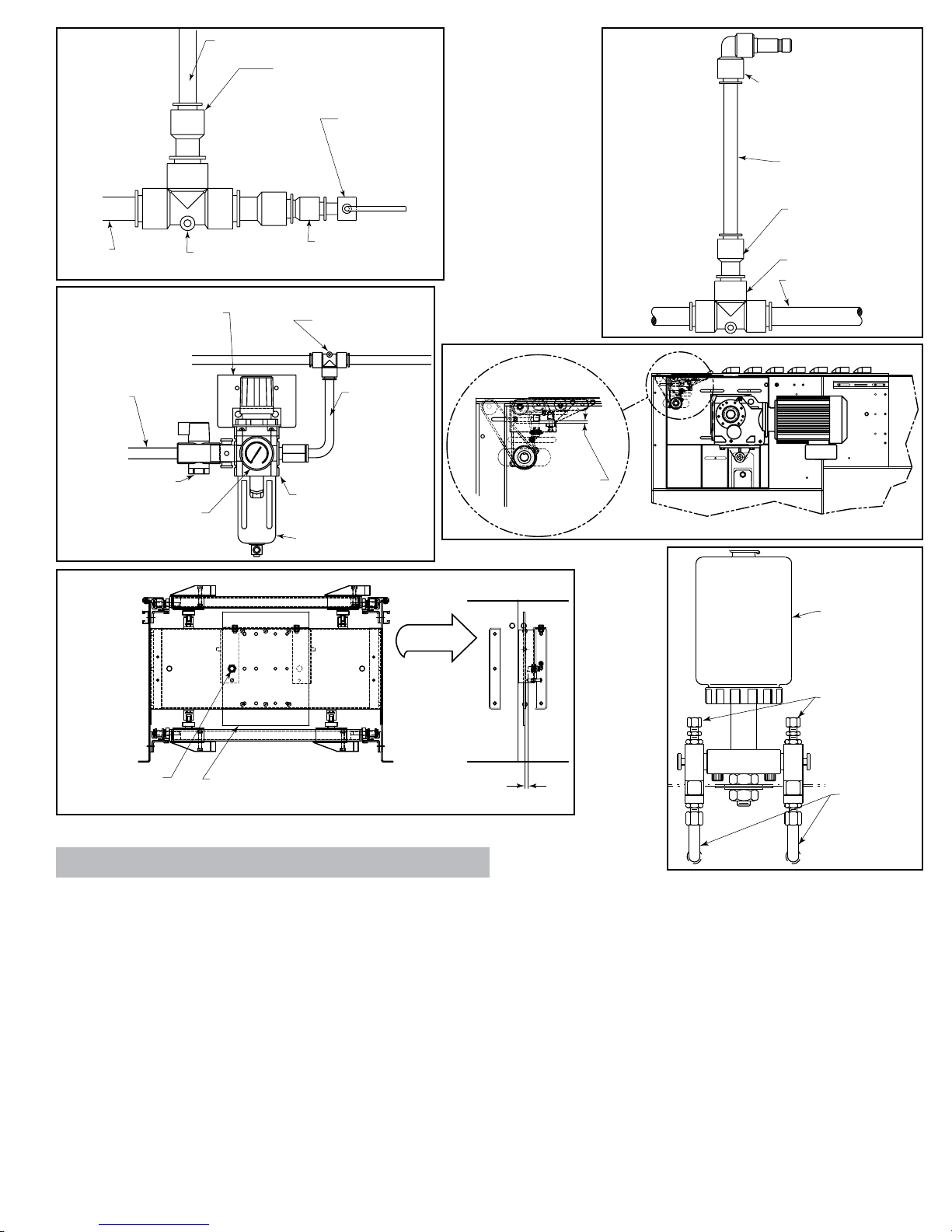
HIGH-SPEED SOLENOID AIR VALVE
The solenoid air valve is used to receive the smart prox output signal and provide
air to the proper end of the divert switch cylinder to move and hold the switch in
either the “home” or “divert” positions. The valve used is specially designed for the
high speed operation necessary for proper divert switch timing.
The two inputs of the solenoid are non-polarized, allowing either lead to be used as
input or ground for the valve. The solenoid requires 24VDC, 4W to operate.
The solenoid air valve is controlled directly by the smart prox. Direct control of this
valve by the controls package is not required or advised.
Other Control Components Supplied with the Conveyor
VARIABLE FREQUENCY DRIVE CONTROLLER
The variable frequency drive (VFD) is a motor controller that has three functions:
1. It provides a smooth acceleration of the drive motor, allowing the sorter to slowly
“ramp up” to full speed. This protects the sorter components from the stress of a
full-speed start up.
2. It allows the speed of the sorter to be adjusted to match speed requirements of
the system. Also, it allows the sorter to be operated at a very slow speed during
installation “Debugging” and when certain mechanical components are checked
after servicing.
3. It allows the sorter to be operated at a slower speed during “off-peak” seasons,
reducing energy consumption, noise, and wear.
Refer to the VFD manufacturer’s installation manual, provided with the sorter, for
wiring and adjustment instructions.
AIR PRESSURE SWITCH
The air pressure switch (Fig. 5A) is used to detect low operating air pressure.
Operation of the sorter at air pressures under 50 PSI can cause erratic switching
and potential switch damage. If air pressure falls below this level, the sorter must
be shut down until the cause of the pressure drop has been found and remedied.
The pressure switch provides a contact-type output which closes at pressures at
or above about 48 PSI and opens below that air pressure. The system controls
provider should use this switch to monitor air pressure at the sorter and should shut
down the sorter if an open (low) output is detected from the pressure switch.
Refer to the pressure switch manufacturer’s installation manual, provided with the
sorter, for wiring instructions.
SAFETY PROXIMITY SWITCHES
There are safety switch devices located at various locations in the sorter to indicate
when a divert shoe is out of place, an obstruction has entered the sorter, or when
some other event has occurred that could cause damage to the sorter or danger to
personnel. These safety switches use normal inductive proximity switches as the
electrical interface to the system controls.
There are two types of safety switches in the sorter:
1. Shoe position safety switches are switch mechanisms inside the sorter that trip
if a divert shoe passes them that is not in its proper track. They are also used to
detect foreign objects that might fall between the slats and enter the interior of the
sorter. They are made to detect problems on both the upper and return portions
of the sorter.
There is one shoe position safety switch located at the infeed end and one at the
discharge end of the sorter. There are additional switches included for every 30
feet of sorter length after the first 30 feet. For example, a sorter 50 feet long will
have a total of 3 switches, a sorter 80 feet long will have a total of 4 switches and
so on. These additional switches are spaced evenly along the sorter’s length.
2. The pop-up transition roller safety switch is used to detect when the transition
rollers on the discharge end of the sorter are in the “up” position. These rollers are
designed to pop up if a stray divert shoe or a foreign object makes contact with
them.
The normal state of the output of the safety proximity switch is”on” (high). If a switch
detects a problem the signal is changed to “off” (low). The system controls must
be configured to go to an “emergency stop” condition and shut down the sorter
and related equipment when a problem is detected. Restart must not be possible
until the problem is corrected and the safety switch that detected the problem is
again “on” (high).
Refer to the proximity switch manufacturer’s installation manual, provided with the
sorter, for wiring instructions.
CATENARY TAKE-UP PHOTO EYE
The catenary take-up photo-eye monitors the amount of chain sag occurring in
the drive’s catenary area. The photo-eye is a retro-reflective, light-operated type,
positioned in the catenary so that if the carrying chains allow the slats to sag below
a certain level, the beam of the eye is blocked.
The system controls must be configured to stop the sorter when the photo-eye
beam is blocked (photo-eye output is “off” or “low”) and provide an indication to
the sorter operator that the chains must be taken up or shortened before operating
the sorter further.
Refer to the photo-eye manufacturer’s installation manual, provided with the sorter,
for wiring instructions.
ENCODER
An encoder is included with the sorter to provide a pulse signal to be used for
product tracking. The encoder provides a square-wave pulse signal of 30 pulses
per revolution of the sorter infeed shaft. This equates to one pulse for every 1.75
inches of sorter travel.
The encoder requires 24VDC power, and provides a 24VDC pulse output.
Refer to the encoder manufacturer’s installation manual provided with the sorter,
for wiring instructions.
CHAIN OILER SOLENOID
The chain oiler is used to provide automatic lubrication of the carrying chains
during sorter operation. When the oiler solenoid valve is energized, oil is allowed
to gravity feed from the oiler reservoir, through metering valves, to brushes located
above the return chains in the sorter.
The system controls should be configured to activate the chain oiler solenoid for a
duration equal to one complete revolution of the carrying chains about every two
hours of operation. The actual amount of oil applied to the chains is controlled by
the metering screws (see “Conveyor Set-up” section of this manual). The chain
oiler solenoid requires 24VDC power to operate.
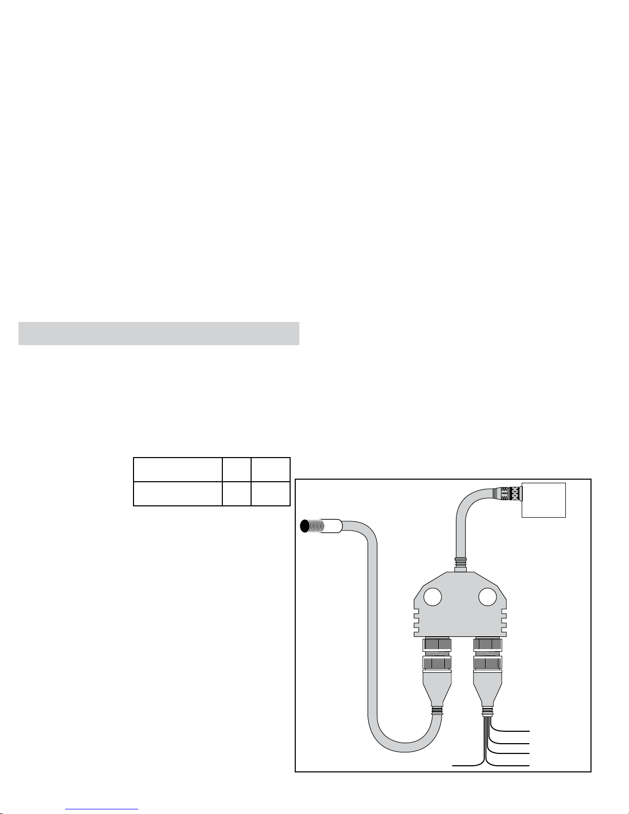
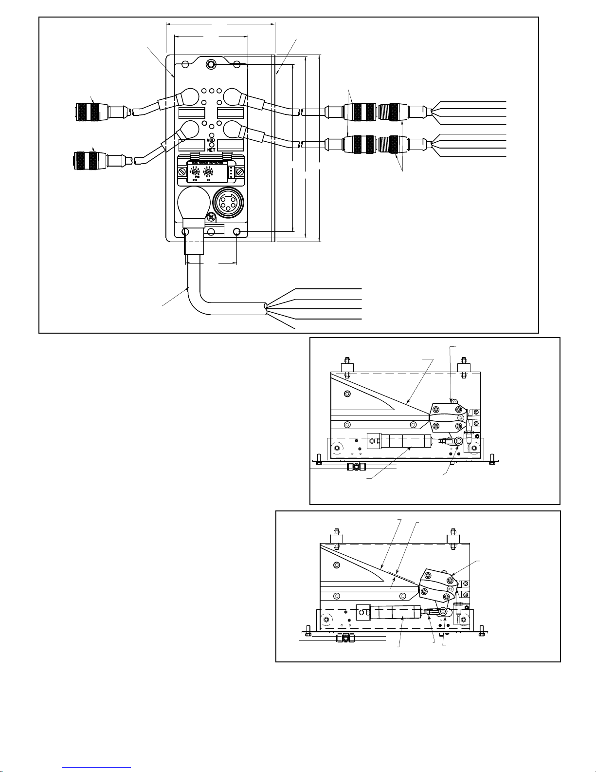
LOST BEARING DETECTION
The missing bearing block is used to detect a bearing missing from a divert shoe.
A divert shoe that does not have a bearing on the bottom can cause damage to
the sorter. The missing bearing block uses two proximity switches located in the
return section of the sorter to detect the presence of a bearing on the shoe. If one
prox detects a bearing being present but the other does not, the block removes
its output to indicate a missing bearing was detected. See figure 8A for location of
missing bearing prox switches.
The missing bearing block requires 24VDC power to operate. The prox switches
are plugged into the left two ports in no particular order. A reset signal of 24VDC
is needed to clear the missing bearing error in the block. The output from the block
is “on” or “high” when no error is detected.
Control Components Not Supplied with the Conveyor
In addition to the control components supplied with the ProSort sorter, there are
several components that must be supplied by the system control provider. Hytrol
recommends the following control components be used to protect the sorter from
damage due to product jams or other problems.
ADJUSTABLE INSTANTANEOUS MOTOR OVERLOADS
Instantaneous overloads provide protection against sorter “hang-ups” by turning
off the drive if a sudden increase in motor current is detected. By adjusting the
overload limit to slightly above the power required to operate the sorter, any
extra load on the motor, such as would be caused by a product jam or switch
malfunction, would cause the sorter to stop, possibly before significant damage is
done to the equipment.
The instantaneous overloads should be installed in the control panel for the sorter
and sized for the proper power requirements.
PHOTO-EYES
Photo-eyes are common components in systems controls. Hytrol recommends that
photo-eyes be installed at the following locations to perform listed functions. These
are, of course, in addition to other photo-eyes needed in the system.
Induction Photo-eye—A photo-eye
mounted at the infeed point of the
sorter. This eye is used to perform the
following functions:
1. Signal the system controls that a
particular package has entered the
sorter. From this point forward, the
package must be tracked using the
encoder pulses to determine when it
reaches the proper divert location.
2. Measure the length of the package
so that the system controls may assign the proper number of divert shoes to the
package for diverting. Note: Shoes are to be assigned for the entire length of the
package plus one extra shoe is to be assigned to the trailing end of the package.
3. Check for the proper gap between packages for safe sorting. It is important to
check for the proper gap here, even if it has been set prior to this point, to insure
that the packages are truly spaced properly. Attempting to sort packages with
too little gap between them can cause jams. Note: The minimum gap necessary
for sorting a package is a function of the width of the package. The charts below
should be used in checking for proper gap.
Jam/Confirmation Photo-eye—Photo-eyes mounted on each take-away spur of
the sorter, as close to the sorter as possible. These eyes perform two functions:
1. Detect a product jam at the sorter “exit point.” If a package blocks this photo-eye
for a longer time than it would take for the package to travel past the photo-eye
normally, this indicated that the package is jammed. The sorter should be stopped
and the jam cleared before restarting the sorter.
2. Divert confirmation. If a divert signal is given to a particular divert point, and no
package is detected by the associated jam/confirmation photo-eye, an error has
occurred. The sorter should be stopped and the error found and corrected before
restarting the sorter.
ProSort 421 (22° Diverts)
ProSort 421 (22° Centros de Desvio)
0”<W≤13”Minimumgap=10”
13”<W≤26”Minimumgap=16”
26”<W≤40”Minimumgap=20”
*W=PackageWidth
Note: When sorting to both sides, the
minimum gap from the above charts must
be increased by 6 in.
7

Full Line Photo-eye—Photo-eyes mounted on each divert lane from the sorter, near
the infeed end of that lane. These eyes are used to signal the system controls that
a particular divert lane is full. The controls should then send any further packages
assigned to that lane to the recirculation line until the full line photo-eye on that lane no
longer indicates the full condition.
Some Control Do’s and Dont’s
The following are recommendations to assist in the design and installation of system
controls that are interfacing with ProSort sorters.
•Donotplace24VDCcontrolwiresinthesamewirewaywithACpowerwires,especially
if the AC power exceeds 240 volts. “Noise” produced in the control wires by the power
wires may produce undesirable effects.
• Do not use optional “standard prox output” of the smart prox as a substitute for an
encoder. The five inch spacing between divert shoes does not provide enough tracking
resolution to accurately sort packages.
•Donotusemanualoverrideoperatorofthesolenoidairvalvetooperateadivertswitch
while the sorter is running. Doing so bypasses the switch timing controls and may cause
switch damage or a sorter crash.
•Dotreat the trippingofanysafetyswitch,motor overload,orlowairpressuresignal
as an emergency stop. Inspect the safety switch and other parts of the sorter to be sure
everything is in good working order before starting or restarting the sorter.
• Pneumatic Divert Switch Checklist
After all ProSort sections are installed and aligned, each divert switch should
be checked for proper operations as follows:
1. Before air pressure is supplied to the divert switch solenoid air valve,
manually pivot the switch back and forth between the non-divert and divert
position checking for a free and smooth pivoting movement. Determine and
remedy the cause of any switch binding. For proper switch alignment see
figures 8B & 8C. If switch adjustment is necessary, loosen the jam nut on the
cylinder rod. Screw cylinder rod into or out of rod end to adjust the switch and
retighten jam nut.
2. Turn air pressure on and verify that each divert switch is in, or moves to, the
home (non-divert) position (Figure 8B).
3. Check to insure that the smart prox is set properly. The face of the prox
should be set just out of the shoe pin guide path in the switch guide (Figure
9A).
• Electric Divert Switch Checklist
NOTE: All electric divert servo motors are paired with the associated drives at the factory. Connecting motors to the wrong drive may have an adverse effect on the divert
operation and could result in physical damage to the sorter. Always connect the drives to the factory paired motors to prevent damage.
1. Before running the sorter, apply power to the electric switch system and verify that the diverts are fully in either the home or diverted position. Divert function was
tested at the factory to ensure proper operation. If the diverts are in the diverted position, they can be returned to the home position by removing the enable signal to the
Smart Prox and then flagging the Smart Prox to trigger a move operation.
2. Check to ensure that the Smart Prox is set properly. The face of the prox should be set just out of the shoe pin guide path in the switch guide (Figure 9B).
AIR CLYINDER
(EXTENDED)
[CIlIndrO de aIre
(eXtendIdO)]
ROD END
(eXtremO de barra)
DIVERT BLOCK
(blOQUe desVIadOr)
SWITCH BLOCK
(NON-DIVERT POSITION)
[blOQUe InterrUptOr
(pOsICIón nO-desVIadOra)
]
DIVERT BLOCK
(blOQUedesVIadOr)
AIR CYLINDER (RETRACTED)
[CYlInder de aIre (COntraÍdO)]
1/16" MIN. 1/8" NORMAL
(1/16" mIn. 1/8" nOrmal)
SWITCH BLOCK
(DIVERT POSITION)
[blOQUe desVIadOr
(pOsICIón desVIadOra)
]
ROD END
(eXtremO de barra)
JAM NUT
(COntra
tUerCa)
FIGURE 8C
3 1/2”
2.355”
5.361”
5.812” 6”
1.649”
Black (Negro) Not Used (No Se Usa)
Blue (Azul) 24VDC (24VDC)
Green/Yellow (Verde/Amarillo) Common
Brown (Café) Not Used (No Se Usa)
White (Blanco) Not Used (No Se Usa)
Brown (Café) Not Used (No Se Usa)
White (Blanco) Not Used (No Se Usa)
Blue (Azul) Common (Común)
Black (Negro) Reset Error (Error Reinicio)
Brown (Café) Not Used (No Se Usa)
White (Blanco) Not Used (No Se Usa)
Blue (Azul) Common (Común)
Black (Negro) Output (salida)
(24V=0K, 0V=Missing
Bearing Detected)
Prox 1
Prox 2
MOUNTING ANGLE
ANGULO DE MONTAJE
MISSING BEARING
DETECTION BLOCK
BLOQUE DE DETECCIÓN
DE RODAMIENTO FALTANTE
Sensor de proximidad 1
Sensor de proximidad 2
FEMALE CABLE EXTENSION
CABLE HEMBRA DE EXTENSION
FEMALE CABLE EXTENSION
CABLE HEMBRA DE EXTENCIÓN
FEMALE CABLE EXTENSION
CABLE HEMBRA DE EXTENCIÓN
4-PIN MALE CABLE
CABLE MACHO GUIA-4
MINIFAST MALE CORDSET
CABLE MINIFAST MACHO
FIGURE 8A
FIGURE 8B
8

1/16"
SWITCH BLOCK MUST
CLEAR PROX SWITCH IN
STRAIGHT THRU POSITION
(EL BLOQUE INTERRUPTOR DEBE
SOBREPASAR EL INTERRUPTOR
PROX EN LA POSICION
RECTA HORIZONTAL)
PROX
SWITCH
1/16"
SWITCH BLOCK
(BLOQUE INTERRUPTOR)
PROX SWITCH
(SENSOR DE
PROXIMIDAD)
SWITCH BLOCK MUST CLEAR PROX
SWITCH IN STRAIGHT THRU POSITION
(BLOQUE INTERRUPTOR DEBE DESPEJAR SENSOR DE PROXIMIDAD
INTERRUPTOR EN POSICION RECTA HORIZONTAL)
FIGURE 9C
SWITCH BLOCK
(NON-DIVERT POSITION)
[BLOQUE INTERRUPTOR
(POSICION NO DESVIADORA)]
DIVERT BLOCK
(BLOQUE DESVIADOR)
FIGURE 9B
A
A
SECTION A-A
SCALE 1 / 2
SERVO MOTOR
SWITCH BLOCK
(DIVERT POSITION)
[BLOQUE INTERRUPTOR
(POSICIÓN DESVIADORA)]
1/16” MIN.
1/8” NORMAL
DIVERT BLOCK
(BLOQUE DESVIADOR)
(SECCIÓN A-A
ESCALA 1/2)
FIGURE 9D
• Carrying Chain Installation
The carrying chains are shipped on marked spools, cut to proper length for each ProSort
conveyor. Steps for installing are as follows:
1. Disconnect electrical power to drive motor to prevent accidental start up.
2. Remove the plug from the motor fan guard, exposing the hex on the motor shaft. Use this
shaft to rotate the motor manually.
3. Check alignment of chain guides by using two short pieces of chain with slat/shoe assemblies
and bearings assembled to pins. This chain/slat/shoe assembly should slide freely through chain
guides in direction of travel for entire length of conveyor.
4. Install carrying chains to both sides of conveyor with pins pointed inward. Make sure the
pins of each chain are directly opposite each other. It will be helpful while installing chains to
install one slat/shoe assembly every 4 feet to hold chain in
guides.
5. Fasten ends of both chains with connector links as shown
in Figure 9E.
6. Install slat/shoe assemblies onto the extended chain pins
on one side of conveyor – being careful to keep the beveled
face of the shoe toward the discharge end and the side with
the rubber insert toward the spur side of conveyor (See
Figure 9F). Lift opposite chain out of chain guide (so chains
may be spread apart) and insert extended chain pins into
opposite end of slat/shoe assemblies.
7. After all slat/shoe assemblies are installed, tighten
carrying chains with take-up bolts at drive shaft. Be sure
drive and tail shafts are square. Retighten all drive take-up
plate mounting bolts. See Figure 10A for proper slack in
chains.
8. Manually crank entire carrying chain assembly through
the conveyor to see that it operates freely and nothing has
been dropped into the conveyor during installation. Also
inspect divert shoes to make sure all of them have been
installed on the correct centers. If chains are ever shortened
it must be in increments of five inches.
9. Replace motor fan guard plug.
10. Reconnect electrical power to drive motor.
CARRYING
CHAIN
(CADENA) BUSHING
(AISLANTE)
BEARING
(RODAMIENTO)
FLOW
(FLUJO)
DIVERT SIDE
(LADO DE DESVIO)
SLAT/SHOE ASSEMBLY
(ENSAMBLE PLACA/ZAPATO)
CONECTOR LINK
(enlaCe)
O-RING
CARRYING
CHAIN
(Cadena)
(O-rIng)
RETAINER
RING
(retenedOr
deanIllO)
FIGURE 9A
FIGURE 9E
FIGURE 9F
9

• Install Guard Rails at
Divert Locations
If guard rails are to be installed on the spurs and/or the
spur side of the sorter, care should be taken to insure
that the guard rails do not interfere in any way with the
boxes being diverted. Particularly, guards should not be
installed in a way that produces a sharp edge or point
in the divert area.
• Locating the Spurs
The take-away spurs must be mounted properly on the
divert sections of the ProSort to insure proper diverting
of product. The following installation guidelines apply to
both powered and gravity spurs.
1. Attach spurs to the sorter by bolting the spur
attachment bracket to the spur mounting nuts in the
unistrut channel on the sorter side channel (Figure
10B). Support the spurs as required. Hand-tighten bolts
only at this time.
2. Manually place 3 or more shoes along the divert
angle as shown. Place a straight-edge against the
shoes to determine the location of the “divert line”.
Verify that the distance between the “divert line” and
the “BR” of the spur is 2 to 3 inches as shown (Figure
10C).
3. Position spur vertically so that the spur rollers/
skatewheels are level with the slats on the sorter.
Tighten mounting bolts.
4. Jackbolt Assembly supplied with spur.
ELBOW FITTING
COVER
PROX SWITCH CORD SET
AIR LINE
(CODO ADJUSTADOR)
(LÍNEA DE AIRE)
(CUBIERTA)
(CABLE DEL INTERRUPTOR
DE PROXIMIDAD)
REMOVE BOLTS
REMOVE LOCK NUTS
(REMUEVA TORNILLOS)
(REMUEVA TUERCAS)
FIGURE 10D
ELBOW FITTING
COVER
PROX SWITCH CORD SET
AIR LINE
(CODO ADJUSTADOR)
(LÍNEA DE AIRE)
(CUBIERTA)
(CABLE DEL INTERRUPTOR
DE PROXIMIDAD)
REMOVE BOLTS
REMOVE LOCK NUTS
(REMUEVA TORNILLOS)
(REMUEVA TUERCAS)
FIGURE 10E
PHOTO-EYE
(FOtO Celda)
(reFleCtOr)
INSTALLATION SETTINGS 10"-14",
PHOTO-EYE WILL DETECT LOW
CATENARY SAG AT 4"
(COnFIgUraCIOnes de InstalaCIOn
10"-14". la FOtO Celda deteCtara la
parte baJa CatenarIa en 4")
REFLECTOR
SPUR SIDE
(espUela lateral) SWITCH SIDE
(InterrUptOr lateral)
FIGURE 10A
DIVERT LINE
(LINEA DESVIADORA) 2" TO 3”
SPUR PLATE
(PLACA DE LA
ESPUELA)
SPUR ATTACHMENT
BRACKET
(BRAZO SOPORTE
DE LA ESPUELA)
UNISTRUT
(CANAL)
JACKBOLT
ASSEMBLY
(CANAL)
FIGURE 10B FIGURE 10C
• Pneumatic Divert Switch
Removal Procedure
The ProSort is designed for easy removal of the divert
switch assembly for maintenance or replacement. In
order to remove the electric switch assembly follow the
following steps.
1. Unplug the elbow from the fitting on the solenoid air
valve by pushing in the red flange of the fitting and then
pulling on the elbow.
2. Disconnect prox switch cord set from y-cable connector
(Figure 6A).
3. Remove the cover located on the side of the sorter
under the divert switch assembly by lifting and rotating
down and out of the way (Figure 10D).
4. By reaching through the uncovered hole in the side
channel remove the two nuts at the back side of the
switch assembly channel. Then remove the two bolts on
the outside of the sorter channel which hold up the front
side of the switch assembly channel (Figure 10E).
5. The front side of the switch assembly channel may then
be lowered and the entire assembly may be removed
through the opening in the sorter channel.
6. Check the new switch assembly according to the
“Divert Switch Checklist” on page 8.
7. Install the new divert switch assembly by reversing the
procedure by which the old assembly was removed.
10
I(@:
0 0
0
0
0 0
0
0 0
0 0
0
0 0 0 0 0 0
0
0 0

• Electric Divert Switch Removal Procedure
The ProSort is designed for easy removal of the divert switch assembly for maintenance or
replacement. In order to remove the electric switch assembly follow the following steps.
1. Turn off all power going into the panel connected to the divert that is needing to be removed. This
includes turning the disconnect on the front of the panel to the OFF position and disconnecting the
3-Phase supply power and control power.
2. Wait at least 90 seconds after removing all power to allow the power to fully dissipate to a safe
level.
3. After waiting 90 seconds, remove the cover located on the side of the sorter under the divert
switch assembly by lifting and rotating down and out of the way. Next remove the orange power
cable and the green encoder cable from the servo motor mounted to the switch. Also remove the
5-wire M12 cable that is connected to the Smart Prox.
4. By reaching through the uncovered hole in the side channel, remove the two nuts at the back
side of the switch assembly channel. Then remove the two bolts on the outside of the sorter channel
which hold up the front side of the switch assembly channel (Figure 11A).
5. The front side of the switch assembly channel may then be lowered and the entire assembly may
be removed through the opening in the sorter channel.
• Electric Switch Homing Procedure
1. Turn off all power going into the panel connected to the divert that is needing to be
homed. This includes turning the disconnect on the front of the panel to the OFF position and
disconnecting the 3-Phase supply power and control power.
2. Wait at least 90 seconds after removing all power to allow the power to fully dissipate to
a safe level.
3. After waiting 90 seconds, remove the cover located on the side of the sorter under the
divert switch assembly by lifting and rotating down and out of the way. Next remove the
orange power cable and the green encoder cable from the servo motor mounted to the switch.
Also remove the 5-wire M12 cable that is connected to the Smart Prox.
4. By reaching through the uncovered hole in the side channel, remove the two nuts at the
back side of the switch assembly channel. Then remove the two bolts on the outside of the
sorter channel which hold up the front side of the switch assembly channel.
5. The front side of the switch assembly channel may then be lowered and the entire
assembly may be removed through the opening in the sorter channel.
6. Remove the nut on the bottom of the switch gate. After the nut is removed, pull the switch
gate out of the assembly. The servo motor shaft and cam should now be visible.
7. Connect the orange power cable and the green encoder cable.
8. Turn the cam by hand until the motor key is facing the outside mounting plate of the switch
assembly.
9. Turn the homing key on the servo drive enclosure on.
10. Apply power to the servo drive enclosure and allow for the drive to power up
completely.
11. Turn off power and remove the homing key.
12. If you reapply power at this point the cam should move to the home position. You can
reinstall the switch gate and check for correct position in both the home and diverted positions.
13. Turn off enclosure power and reinstall the electric switch assembly.
• Trouble Shooting
The following charts list possible problems that may occur in the operation of the ProSort.
TROUBLE SHOOTING DRIVES
TROUBLE CAUSE SOLUTION
Conveyor will not start or shuts off
automatically during operation.
1) Jam eye blocked
2) Tripped internal safety switch.
3) Pop-up rollers “UP”.
4) Proximity switch for internal safety switch or pop-up
rollers mis-adjusted or defective.
5) Low air pressure.
a) Regular set low.
b) Air line restricted or broken.
c)Airlterclogged.
d) Compressor problem.
e) Lockout closed.
6) Electrical circuits.
7) Variable speed drive mis-adjusted or defective.
8) Drive motor defective.
1) Unblock jam eye.
2) Determine cause of tripping: foreign debris, mislocated divert shoes, etc.,
and correct problem.
3) Determine reason for rollers popping up and correct problem.
4) Adjust or replace proximity switch.
5) Determine reason for low air pressure and correct problem.
6) Check power and wiring.
7) Refer to variable speed drive manufacturer’s manual for trouble shooting.
8) Replace motor.
Conveyor takes long time to reach
speed or conveyor jerks when starting. 1) Variable speed drive mis-adjusted or defective. 1) Refer to variable speed drive manufacturer’s manual for trouble shooting.
Divert shoes "jump" during diverting.
1) Divert shoe tight on slats.
2) Slats dirty.
3) Slats bent.
4) Switch mis-adjusted.
1) Replace slat/shoe assembly.
2) Clean surface. (Refer to Preventive Maintenance Details)
3) Replace slat/shoe assembly.
4) Refer to Divert Switch Checklist, Page 8 & 9.
Inoperative divert switch.
1) No air pressure to cylinder.
2) Lockout closed.
3) Air solenoid valve defective.
4) Proximity switch mis-adjusted or defective.
1) Check air line and filter regulator. Replace if necessary.
2) Open lockout.
3) Replace.
4) See page 8 & 9 for proper adjust or replace.
All divert switches inoperative. 1) Loss of power to air solenoid valves.
2) Controls failure. 1) Correct problem.
2) Trouble shoot control system.
Inoperative electric divert switch 1) No power to electric switch. 1) Check 3-Phase power to the servo drive enclosure.
REMOVE BOLTS (RETIRE TORNILLOS)
REMOVE LOCK NUTS
(RETIRE TUERCAS)
FIGURE 11A
PROX SWITCH CORD SET
(CABLE DEL INTERRUPTOR
DEL SENSOR DE PROXIMIDAD)
ORANGE
(NARANJA)
GREEN
(VERDE)
ELECTRICAL CONTROL BOX
(CAJA DE CONTROL ELECTRICA)
FIGURE 11B
11
0
0
'
"
"
"
0"
.!
==dJ
0 0
0
0
0
0
0
0
0 0
0
0
0
0
0
0 0

HYTROL
HYTROL
HYTROL
HYTROL
HYTROL
25
94
104 105 95
548
1
23
21 6
87
47 3045 12 2915
4
26
9
58
24
11
57
56
96
2
22
23 46 13 3
99 10
103
102
100
60
59
19
14
28
44
43
41
93
92
91
31
27
37
38
51
52
53
35
36
39
40
42
43
18
16
63
78 55 54 50
17 33
34
49 20
44
32
• Model ProSort 421 Parts Drawing Dibujo de Partes del Modelo ProSort
421
Catenary Divert and Drive Section
(Catenaria de Desviación y Sección Motriz)
12

62 89 76
98
97
83
84
87
88
101
HYTROL
HYTROL
HYTROL
HYTROL
HYTROL
HYTROL
HYTROL
64
63 66 70 85
72
63
64 61 67 71 73
74
75
63
78
77
63 82 86107
106
65 79
80
81
68
69
90
• Model ProSort 421 Parts Drawing Dibujo de Partes del Modelo ProSort
421
Intermediate and Return Divert Section
(Secciones de Desviación Intermedia y de Retorno)
NOTE:
Place chain covers so that no
seams are located within the spur/
diverting area.
NOTA:
Coloque las cubiertas de cadena para
que no haya empalmes en el área de
desvío con la espuela.
13

132
133
120
123
119
127
118
126
125
124
110
122 134
HYTROL
HYTROL
HYTROL
HYTROL
HYTROL
116
117
131
130129
114
112108
121
113
114
128
109 111
46
47
115
• Model ProSort 421 Parts Drawing Dibujo de Partes del Modelo ProSort
421
Tail and Divert Section
(Seccion de Descarga Desviación)
14
I
I
o'•
I
I
'•
···:···----~--------~--------~--------~-----=---~--------~-----·-·:··----~-
..

162 135 149 139
158
136 163 141
142 164
165
161
167 146 166
143
144
FLOW/FLUJO
170
174 176 175 180
179
172
173 171
169 168
154 153147
156
157 177
178 137
160
155 138 159
152 145 150
151 148 140
• Model ProSort 421 Parts Drawing Dibujo de Partes del Modelo ProSort
421
Induction Unit (Unidad de Inducción)
REF NO. PART NO. DESCRIPTION
1
2
3
---
---
WA-015050-L
WA-015050-R
---
WA-015252
WA-015064
Drive Side Chnl Weldment - LH
Drive Side Chnl Weldment - RH
Take-Up - Drive Side
Left Hand
Right Hand
4
---
---
5
6
---
WA-015120
WA-015254
WA-014976
MP-001196-012
Take-Up - Slave Side
Left Hand
Right Hand
Bed Spacer Assembly (Specify OAW)
Spur Mounting Channel
7
8
9
---
---
PT-053021
PT-052597
---
PT-103580
PT-103581
Pin Guide Support Plate
Top Stiffener Plate
Drive Shaft
KT77 Gearmotor (Specify OAW)
KT97 Gearmotor (Specify OAW)
10
11
12
13
14
B-23250
WA-015169
WA-015259
B-23258
SA-037195
End Cover (Specify OAW)
End Plate Weldment (Specify OAW)
Slave Drive Guard
Bearing Spacer
Transition RollerAssembly (Specify OAW)
15
16
17
18
19
PT-087686
PT-052599
B-23281
B-23285
---
Transition Drive Shaft (Specify OAW)
Catenary Take-Up Wearstrip
Support Weldment (Specify OAW)
Torque Arm Mounting Weldment for KT77 Gearmotor
1.9 Dia. Transition Roller
REF NO. PART NO. DESCRIPTION
---
---
---
---
---
SA-038920-240
SA-038920-288
SA-038920-336
SA-038920-384
SA-038920-432
30 in BR
36 in BR
42 in BR
48 in BR
54 in BR
20
21
22
23
24
PT-051623
PT-11580-L
PT-11580-R
PT-052971
932.0079
Splice Channel
Chain Wearstrip - LH
Chain Wearstrip - RH
Chain Guide Mounting Angle
Cushion Disk
25
26
27
28
29
B-17065
SA-042719
010.0021
010.2075
020.130
Pin Guide Spacer
Sprocket 100E42 W/Lagging
Bearing - Cast Iron, 2-Bolt, 1" Bore
Bearing - Cast Iron, 4-Bolt, 2-15/16" Bore
Sheave - 1A, 2.75" OD x 1" Bore (2.5"PD)
30
31
32
33
34
024.1615
32.2116
941.423003
042.664
041.798
Sheave - 1A, 12.25" OD x 1" Bore (12"PD)
Proximity Switch - DC, Normally Open
Cordset - 3M, Straight Female
3/8-16 x 2-3/4" Lg Hex Skt Flt Hd Cap Screw
3/8-16 NC2B Hex Locknut - Nylon Insert
35
36
37
38
39
040.504
041.503
049.5205
041.2021
040.700
5/8-11 x 4-1/2" Lg Hex Head Cap Screw
5/8-11 NC2B Hex 2-Way Locknut - Regular
5/8-18 x 6" Lg Hex Head Bolt - Hardened
5/8-18 NC2B Hex Jam Nut - Regular
7/8-9 x 2" Lg Hex Head Bolt for KT77 Gearmotor
• Model ProSort 421 Parts List Lista de Partes del Modelo ProSort
421
15

• Model ProSort 421 Parts List Lista de Partes del Modelo ProSort
421
REF NO. PART NO. DESCRIPTION
40
41
42
43
44
040.701
042.700
043.1059
043.207
041.107
7/8-9 x 6" Lg Hex Head Bolt for KT97 Gearmotor
7/8-9 x 2-1/2" Lg Hex Skt Flat Hd. Cap Screw
7/8" ID Flat Steel Washer
7/8" ID Split Lockwasher
7/8-9 NC2B Hex Nut - Regular
45
46
47
48
49
090.2547
918.0056
918.0055
092.1813
092.1838
O-Ring - 13-1/2" ID x 3/8" Dia.
Chain Guide Support Block - LH
Chain Guide Support Block - RH
Offset Pin Guide
Catenary Block
50
51
52
53
54
033.2130
032.2185
042.1019
041.802
033.2131
Photoeye-Retro-Reective,10-40VDC
Reector-3.30"Dia.
#10-24 x 3/4" Lg Round Head Mach Screw
#10-24 NC2B Hex Locknut - Nylon Insert
Photoeye Mounting Bkt - Ball Swivel
55
56
57
58
59
032.21122
PT-098832-384
PT-057740
098.1871
PT-066395
Cordset - for Photoeye
Brush - Drive
Brush Holder - Drive
Collar - 2-15/16" ID
Reinforcing Strap
60
61
62
63
64
090.2564
PT-083916
MP-001196
P-00447
PT-052310
O-Ring - 5-3/8" ID x 3/16" Dia.
Intermediate Channel (Specify OAL)
Spur Mounting Channel - Intermediate (Specify OAL)
Chain Guide Wearstrip (Specify OAL)
Chain Guide Mtg Angle - (Specify OAL)
65
66
67
---
PT-054987
PT-066797
---
SA-022167
Joint Plate
Joint Plate - Long
Switch Assembly, Pneumatic - See Page 33 & 34
Left Hand
---
68
---
---
69
70
SA-022196
---
SA-054961
SA-052517
EB-000011
PT-052309
Right Hand
Switch Assembly, Electric - See Page 35 & 36
Left Hand
Right Hand
Control Panel - Electric Divert Switch
Divert Channel - LH (Specify OAW and LH)
71
72
73
74
---
PT-052309
WA-015033
PT-054571
---
P-01509-0494
Divert Channel - RH (Specify OAW and RH)
Switch Mounting Channel Weldment
Divert Angle (Specify OAW)
Mounting Strap
33 in OAW
---
---
---
---
75
P-01509-0752
P-01509-1011
P-01509-1269
P-01509-1528
---
39 in OAW
45 in OAW
51 in OAW
57 in OAW
Divert Wearstrip
---
---
---
---
---
0110-0064-0988
0110-0064-1505
0110-0064-2022
0110-0064-2539
0110-0064-3056
33 in OAW
39 in OAW
45 in OAW
51 in OAW
57 in OAW
76
77
78
79
80
MP-001198
PT-052312
PT-055292
PT-056365
PT-67116
Spur Mounting Channel - 22 Deg Divert (Specify OAW)
Chain Guide Mtg Angle - 22 Deg Divert (Specify OAW)
Chain Guide Mtg Angle - 22 Deg Cat. Divert (Specify OAW)
Chain Guide Mtg Angle- End Divert (Specify OAW)
Return Y-Block Mtg Plate - 22 Deg
81
---
---
82
83
---
092.179752
092.179751
PT-051905
PT-052231
Return Y-Block - 22 Deg
Left Hand
Right Hand
Y-Block Mounting Plate
Cover Plate - Switch Side
84
85
86
---
---
PT-060165
B-18446
---
092.17972
092.17971
Cover Plate - Spur Side
Track Spacer
Y-Block - 22 Deg
Left Hand
Right Hand
87
88
89
---
---
042.914
049.527
---
092.18696
092.18695
Shoulder Bolt - ACC Suspension Angle
1/4-20 Small Flange Locknut
Shoe Assembly
LH Shoe
RH Shoe
90
91
92
93
94
SA-057188
Contact Factory
Contact Factory
Contact Factory
099.462
Slat Assembly (Specify OAW)
GearMotor
Variable Speed Controller Kit
Control Package
Aluminum Guide Rail Extrusion x 20' Long
95
96
97
099.463
069.751
094.423
Special Shape UHMW Guide Rail x 20' Long
BearingProle-Urethane
Chain Cover - Black PVC
REF NO. PART NO. DESCRIPTION
98
99
100
101
102
103
104
041.9069
029.2657
029.2667
082.4157
096.114
WA-015017
PT-051907
Speed Grip Nut Retainer - 1/4-20
#100XLO Riveted O-ring Chain W/D1 Att
Connector Link - #100XLO W/1.75" Lg D1 Att
Channel Nut - 3/8-16 With Spring
Loctite Instant Adhesive - #401
Bed Spacer Weldment - Catenary (Specify OAW)
Safety Block Mounting Plate
105
106
107
108
109
092.1807
PT-051908
092.1809
PT-053732-L
PT-053732-R
Safety Shoe Guide
Return Block Mounting Plate
Return Sweep Block - 22 Deg
Tail Channel - LH
Tail Channel - RH
110
111
112
113
114
115
WA-015562
PT-053737
PT-115582-L
PT-115582-R
PT-053735
PT-053731
End Bed Spacer Weldment (Specify OAW)
Tail Pin Guide Mounting Plate
Chain Wearstrip - LH
Chain Wearstrip - RH
Chain Guide Mounting Angle - Tail
Shoe Guard Support Channel
116
117
118
---
---
119
SA-023332
PT-103582
---
B-23212
B-23213
PT-057975
Sprocket Idler 100B42 W/Lagging
Tail Shaft - Slave for Induction Conveyor (Specify OAW)
End Shoe Cover
Left Hand for Left hand Drive Unit
Right Hand for Right Hand Drive Unit
Bearing Spacer Angle
120
121
122
123
124
125
B-18469
B-18450
095.155
095.150
043.205
042.581
Oiler Brush Bracket
Oiler Mount Bracket
Shank Brush for Chain lubricator
Chain Lubricator W/2 Feeds, 24V DC
3/4" ID Split Lockwasher
3/4-10 x 2-1/2” Lg Carriage Bolt
126
127
128
129
130
041.106
010.2076
092.18101
PT-057731
PT-057738
3/4-10 NC2B Hex Nut - Regular
Bearing - Cast Iron 4-Bolt, 2-15/16" Bore
Tail Pin Guide Block
Brush Mounting Bar - Tail
Brush Holder - Tail
131
132
133
134
135
PT-098832-288
PT-063104
932.0076
PT-126624
PT-063278-L
Brush - Chain Cover, Tail
Belt Flap Mounting Angle
Belt Flap for End Cover
Cover Plate
Drive Side Plate - LH (Induction Unit)
136
137
138
139
140
PT-063278-R
B-23159
B-23162
B-23165
B-23575
Drive Side Plate - RH (Induction Unit)
Cover Assembly
Pulley Plate Assembly
8" Drive Pulley (Specify OAW)
2-1/4" Dia Pulley (Specify OAW)
141
---
---
142
143
---
PT-054187
PT-054252
PT-054188
PT-063281
Slave Guard
Left Hand for Left Hand Drive Unit
Right Hand for Right Hand Drive Unit
Slave Guard Cover
Drive End Channel (Specify OAW)
144
145
146
147
148
PT-054189
PT-054185
PT-062544
B-23294
B-23295
Pulley Mounting Bracket
Induction Drive Channel
Slave Guard Mounting Bracket
Bolt in Slider Pan (Specify OAW)
Nip Point Guard (Specify OAW)
149
150
151
152
153
B-23296
B-04161
B-09148
B-23297
B-04842
6" Take-Up Pulley (Specify OAW)
Bearing Guide
Bearing Guide Spacer
Take-Up Plate Assembly
11/16" Hex Idler Bracket
154
---
---
---
---
---
B-15299-120
B-15299-168
B-15299-216
B-15299-264
2-1/2" Roller - Conveyor Frame
15" BR
21" BR
27" BR
33" BR
---
155
---
---
---
B-15299-312
---
B-15299-240
B-15299-288
B-15299-336
39" BR
2-1/2" Roller - Drive Shell
30" BR
36" BR
42" BR
---
---
156
157
158
B-15299-384
B-15299-432
B-23299-L
B-23299-R
B-23300
48" BR
54" BR
Butt Coupling - LH
Butt Coupling - RH
Top Drive Cover - Slave Side
159
160
161
162
B-23301
B-23302
B-23304
B-23116
Lower Drive Guard (Specify OAW)
Take-Up Bolt
Idler Plate
Top Drive Cover
16

REF NO. PART NO. DESCRIPTION
163
164
165
166
167
168
010.203
010.2045
108.044327
108.090332
108.816003
P-01431
1-7/16” Bore 4-Bolt Bearing
1-11/16" Bore 4-Bolt Bearing
44PTH8 - 35SD x 1-11/16" Bore Timing Belt Sprocket
90PTH8 - 35SF x 2" Bore Timing Belt Sprocket
1600PTH8M - 35 Timing Belt
Side Channel Induction Unit (Specify OAL)
169
170
---
---
---
B-03916
---
0265-084120
0265-108120
0265-132120
Bed Spacer (Speify BR)
Bolt in Pan 18" OAW
10-1/2 in. Long Pan
13-1/2 in. Long Pan
16-1/2 in. Long Pan
---
---
---
---
---
0265-144120
0265-156120
0265-168120
0265-172120
0265-174120
18 in. Long Pan
19-1/2 in. Long Pan
21 in. Long Pan
21-1/2 in. Long Pan
21-3/4 in. Long Pan
---
---
---
---
---
0265-180120
0265-186120
0265-188120
0265-192120
0265-196120
22-1/2 in. Long Pan
23-1/4 in. Long Pan
23-1/2 in. Long Pan
24 in. Long Pan
24-1/2 in. Long Pan
---
---
---
---
---
0265-198120
0265-204120
0265-210120
0265-212120
0265-216120
24-3/4 in. Long Pan
25-1/2 in. Long Pan
26-1/4 in. Long Pan
26-1/2 in. Long Pan
27 in. Long Pan
---
---
---
---
---
0265-220120
0265-222120
0265-228120
0265-240120
0265-252120
27-1/2 in. Long Pan
27-3/4 in. Long Pan
28-1/2 in. Long Pan
30 in. Long Pan
31-1/2 in. Long Pan
---
---
---
---
---
---
0265-084168
0265-108168
0265-132168
0265-144168
Bolt in Pan 24" OAW
10-1/2 in. Long Pan
13-1/2 in. Long Pan
16-1/2 in. Long Pan
18 in. Long Pan
---
---
---
---
---
0265-156168
0265-168168
0265-172168
0265-174168
0265-180168
19-1/2 in. Long Pan
21 in. Long Pan
21-1/2 in. Long Pan
21-3/4 in. Long Pan
22-1/2 in. Long Pan
---
---
---
---
---
0265-186168
0265-188168
0265-192168
0265-196168
0265-198168
23-1/4 in. Long Pan
23-1/2 in. Long Pan
24 in. Long Pan
24-1/2 in. Long Pan
24-3/4 in. Long Pan
---
---
---
---
---
0265-204168
0265-210168
0265-212168
0265-216168
0265-220168
25-1/2 in. Long Pan
26-1/4 in. Long Pan
26-1/2 in. Long Pan
27 in. Long Pan
27-1/2 in. Long Pan
---
---
---
---
---
0265-222168
0265-228168
0265-240168
0265-252168
---
27-3/4 in. Long Pan
28-1/2 in. Long Pan
30 in. Long Pan
31-1/2 in Long Pan
Bolt in Pan 30" OAW
---
---
---
---
---
0265-084216
0265-108216
0265-132216
0265-144216
0265-156216
10-1/2 in. Long Pan
13-1/2 in. Long Pan
16-1/2 in. Long Pan
18 in. Long Pan
19-1/2 in. Long Pan
---
---
---
---
---
0265-168216
0265-172216
0265-174216
0265-180216
0265-186216
21 in. Long Pan
21-1/2 in. Long Pan
21-3/4 in. Long Pan
22-1/2 in. Long Pan
23-1/4 in. Long Pan
---
---
---
---
---
0265-188216
0265-192216
0265-196216
0265-198216
0265-204216
23-1/2 in. Long Pan
24 in. Long Pan
24-1/2 in. Long Pan
24-3/4 in. Long Pan
25-1/2 in. Long Pan
---
---
---
---
---
0265-210216
0265-212216
0265-216216
0265-220216
0265-222216
26-1/4 in. Long Pan
26-1/2 in. Long Pan
27 in. Long Pan
27-1/2 in. Long Pan
27-3/4 in. Long Pan
---
--- 0265-228216
0265-240216 28-1/2 in. Long Pan
30 in. Long Pan
REF NO. PART NO. DESCRIPTION
---
---
---
---
---
---
---
---
0265-252216
---
0265-084264
0265-108264
0265-132264
0265-144264
0265-156264
0265-168264
31-1/2 in Long Pan
Bolt in Pan 36” OAW
10-1/2 in. Long Pan
13-1/2 in. Long Pan
16-1/2 in. Long Pan
18 in. Long Pan
19-1/2 in. Long Pan
21 in. Long Pan
---
---
---
---
0265-172264
0265-174264
0265-180264
0265-186264
21-1/2 in. Long Pan
21-3/4 in. Long Pan
22-1/2 in. Long Pan
23-1/4 in. Long Pan
---
---
---
---
0265-188264
0265-192264
0265-196264
0265-198264
23-1/2 in. Long Pan
24 in. Long Pan
24-1/2 in. Long Pan
24-3/4 in. Long Pan
---
---
---
---
---
0265-204264
0265-210264
0265-212264
0265-216264
0265-220264
25-1/2 in. Long Pan
26-1/4 in. Long Pan
26-1/2 in. Long Pan
27 in. Long Pan
27-1/2 in. Long Pan
---
---
---
---
---
0265-222264
0265-228264
0265-240264
0265-252264
---
27-3/4 in. Long Pan
28-1/2 in. Long Pan
30 in. Long Pan
31-1/2 in. Long Pan
Bolt in Pan 42" OAW
---
---
---
---
---
0265-084312
0265-108312
0265-132312
0265-144312
0265-156312
10-1/2 in. Long Pan
13-1/2 in. Long Pan
16-1/2 in. Long Pan
18 in. Long Pan
19-1/2 in. Long Pan
---
---
---
---
---
0265-168312
0265-172312
0265-174312
0265-180312
0265-186312
21 in. Long Pan
21-1/2 in. Long Pan
21-3/4 in. Long Pan
22-1/2 in. Long Pan
23-1/4 in. Long Pan
---
---
---
---
---
0265-188312
0265-192312
0265-196312
0265-198312
0265-204312
23-1/2 in. Long Pan
24 in. Long Pan
24-1/2 in. Long Pan
24-3/4 in. Long Pan
25-1/2 in. Long Pan
---
---
---
---
---
0265-210312
0265-212312
0265-216312
0265-220312
0265-222312
26-1/4 in. Long Pan
26-1/2 in. Long Pan
27 in. Long Pan
27-1/2 in. Long Pan
27-3/4 in. Long Pan
---
---
---
171
---
0265-228312
0265-240312
0265-252312
---
B-01982-120
28-1/2 in. Long Pan
30 in. Long Pan
31-1/2 in. Long Pan
1.9 O.D. Galv. Roller Assy.
15" BR
---
---
---
---
172
B-01982-168
B-01982-216
B-01982-264
B-01982-312
---
21" BR
27" BR
33" BR
39" BR
2-1/8 " Dia. Idler
---
---
---
---
---
B-03894-120
B-03894-168
B-03894-216
B-03894-264
B-03894-312
15" BR
21" BR
27" BR
33" BR
39" BR
173
174
175
176
177
B-00944
B-23575
B-23578
B-23579
B-23581-L
7/16" Hex Idler Bracket
2-1/4" Dia. Pulley (Specify BR)
Pulley Mount
Nip Point Guard (Specify BR)
Gussett Angle - LH
178
179
180
181
182
B-23581-R
B-03191
B-23585
SA-061960
B-24596
Gussett Angle - RH
Butt Coupling
Belt Kit (Specify Infeed Section Lgth and OAW)
Pull Assembly (Specify OAW) (Not Shown)
Chain Pick-Up Tool - Flat (Not Shown)
183
184
185
186
187
B-24591
SA-023516
032.293
042.49010
PT-093001
Chain Pick-Up Tool - Bent (Not Shown)
Safety Switch Assembly - See Page 37
Encoder - 30PPR (Not Shown)
1/4 x 1-1/4 Lg Shoulder Bolt (Not Shown)
End Coder Cover (Not Shown)
• Model ProSort 421 Parts List Lista de Partes del Modelo ProSort
421
17

16
89
88
87
44
43
42
41 28 14 19
31
27
37
38
51
52
53
35
36
39
40
43
44
18
20
49
33
34
17
50
54
55
63
64
32
100 25 5
23
21 16847 73045
1229 15
426
58
9
24
11
57
56
3
13
46
99
10
90
91 222
23
101 48
60
59
• Model ProSort 431 Parts Drawing Dibujo de Partes del Modelo ProSort
431
Catenary Divert and Drive Section
(Catenaria de Desviación y Sección Motriz)
18

• Model ProSort 431 Parts Drawing Dibujo de Partes del Modelo ProSort
431
Intermediate and Return Divert Section (Secciones de Desviación Intermedia y de Retorno)
97
62 85 75 94
93
83
84
79
80
97
HYTROL
HYTROL
HYTROL
HYTROL
HYTROL
65 81 69 102
103 82 78
63
64
72
73
74
70
95
96
66
98
92
61
63
64
71
76
77
86
67
68
19

• Model ProSort 431 Parts Drawing Dibujo de Partes del Modelo ProSort
431
Tail and Divert Section (Seccion de Descarga Desviación)
HYTROL
HYTROL
HYTROL
127
126
125 104 6364
112
113
107
124
105
117
115
108
110
109
110
111
128129
116
119
114
122
121
120
106
118
123
130
20
rr
·
----
oo
----------------- ------------
--~--------~--------~---·:·~-~-------~--------~------~~
------
------
This manual suits for next models
1
Table of contents
Other HYTROL Accessories manuals