solexx Garden Master G-512 User manual

ADAPT8, INC - MAKERS OF SOLEXX™ GREENHOUSES 1-877-476-5399
ASSEMBLY INSTRUCTIONS
12’ X 8’ X 8’9” Garden Master
G-512 (3.5mm)
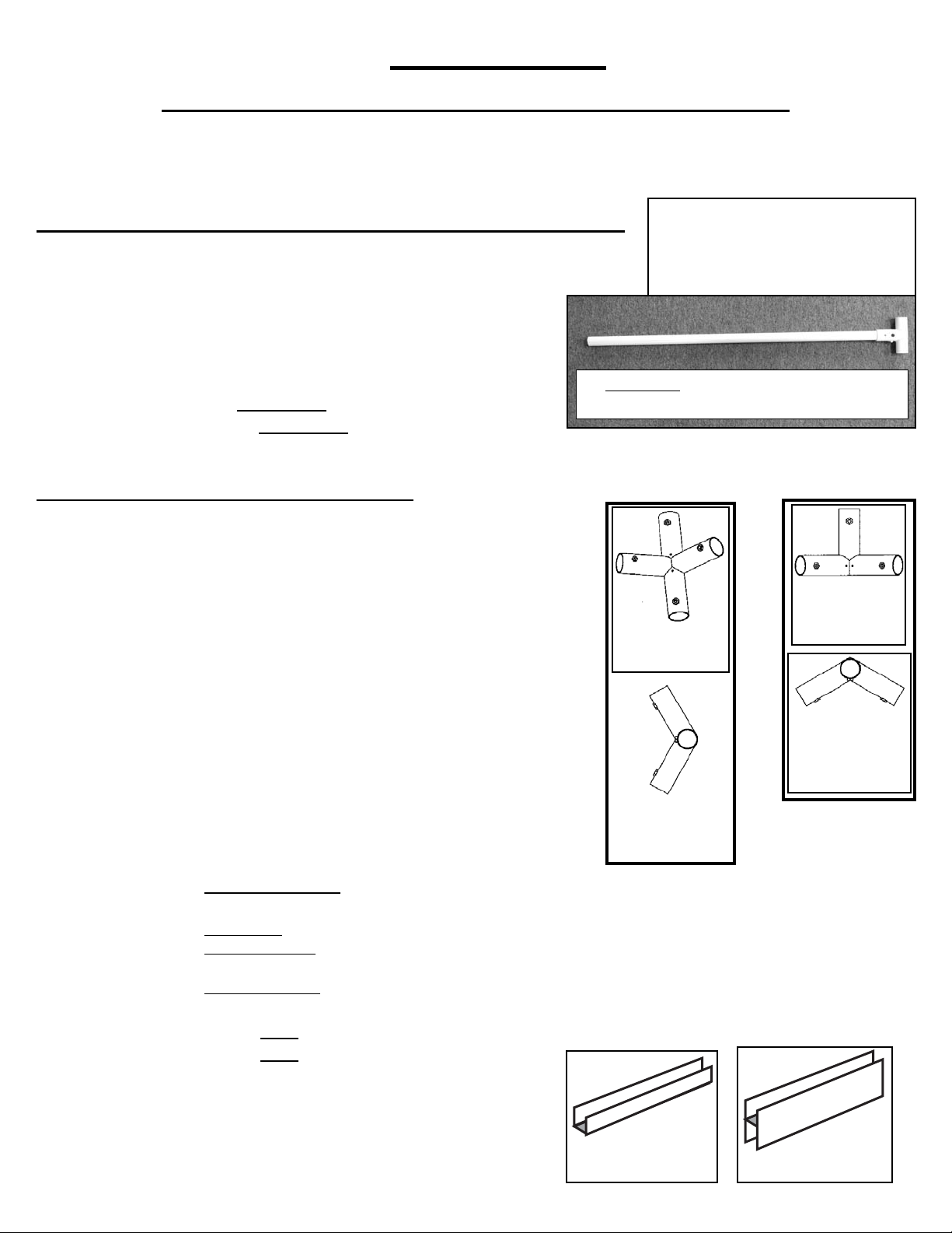
This kit includes (3) double-decker benches, (2) hanging rods and (1) Louver.
Assembly Required - All pipe has been precut - (No cutting is required.)
It is important to panel the greenhouse frame once it is completed and before it is rained on.
The protective coating on the fittings is to protect the fittings from rust due to moisture or
condensation. The protective coating was not designed for the volume of water produced when
the fittings are rained on for a period of time with out the paneling on the greenhouse.
TOOLS PROVIDED:
A. ¼” nut driver
TOOLS NEEDED:
A. VARIABLE SPEED DRILL
B. SCREWDRIVER
C. LONG SHARP KNIFE
D. TAPE MEASURE
E. STEP LADDER
F. PLIERS
G. 2-3 tubes “Clear” 100% silicone (We recommend IS800 Silicone Rubber Adhesive Sealant) & a
Caulking Gun
H. 8 oz. can of “Clear” PVC CEMENT (Available at a hardware store). **
I. DUCT TAPE
**Follow the instructions on the glue can. Do not apply glue if it is colder than the
instructions indicate for proper use.
uNOTE: GLUE DRIES VERY QUICKLY! Hold pipe into fitting for 30 seconds until the glue has set.
Please read instructions carefully and refer to the diagrams.
uuAttention:
There are two types of frame tubing in your kit. The Composite Tubing is a heavier thick-walled tubing
that has a gray fiber weave throughout (looks like a fiber texture) while the PVC tubing is a thin-walled
tubing. The super strong Composite Tubing will be used for the structural areas of the greenhouse frame.
The PVC is used in areas where the pipe needs to be flexible to bend or in non-structural areas.
Feb 20
12’ Garden Master (3.5mm) Page 1
PARTS LIST
12' X 8' X 8'9” Garden Master With 3.5mm Solexx™ Paneling
G-512 (3.5mm)
*Please make sure your kit includes all the following parts before you begin assembly
ROLL BOX 1 106 lbs (24” x 24” x 51”) - Box 1 & 2 = 145 / 146 lbs.
____ 2 49 ½" x 145" Panels
_____ 4 42" x 145" Panel
_____ 1 42" x 115" Panel
_____ 1 36 ½” x 80” Door Panel
_____ 4 31" x 94 ½" Panels
_____ 1 29" x 42" Panel
_____ 7 44” Composite Tubing - Red
_____ 3 35 ¾" Composite Tubing - White
_____ 1 33” Composite Tubing- Cross Bar with Snap T (for door) - Slotted
INNER BOX 2 51 lbs (10” x 10” x 50”)
Bag #1_____ 10 4-Way 120° Metal-T’s
Bag #2_____ 5 4-Way 120° Metal-T’s
Bag #3_____ 6 3-Way 120° Metal Corner Post’s
Bag #4_____ 8 Metal Corner Posts
Bag #5_____ 8 4-way Metal-T’s
Bag #6_____ 8 4-way Metal-T’s
Bag #7
_____ 4 90° Metal Elbow
_____ 8 Metal Rings
_____ 8 1 ½" x 3/16" Machine Screws
_____ 8 3/16" Wing Nuts
_____ 5 Yellow Banding
_____ 5 Metal Banding Clips
_____ 35 Small Phillips Screws
_____ 1 Door Parts Bag:
Outside Handle, Inside Handle, 3-point Cam
Hinge Bag: 1/4” x 1-3/4” Bolts (4), Lock Nuts (4), Hinge halves and pins (2), Flat Washers (2)
Door Parts Bag: 8/32 Hex Lock Nut, 3/8” Lock Nut, 32 x 1-3/4” Machine Screw, 1” Metal Screw,
4mm Allen Wrench
Door Cable Bag: Turnbuckle, 76” Wire Cable, 1/16” Wire Cable Clamps (2)
Bag #8
_____ 4 PVC Elbows
_____ 4 PVC 2" Nipples
_____ 9 Large Black Zip Ties
_____ 545 1" Screws
_____ 1 ¼" Driver
Feb 20
3-Way
120° Metal
Corner Post
3-Way
120° Metal
Corner Post
(Top View)
4-Way 120°
Metal-T
4-Way 120°
Metal-T
(Top View)
U Trim H-Channel
NOTE: To conserve shipping space,
U-Trim and 1/2” diameter tubibng are
sometimes inserted into 3/4” tubing.
Please check frame pieces before
assembly.
33” Composite Cross Bar with Snap T (for
door) - slotted
12’ Garden Master (3.5mm) Page 3
G-512 (3.5mm)
BOX 3 56 lbs (99” x 7 ¼” x 5”)
_____ 3 94 ½" Composite Tubing - Green
_____ 3 94 ½” Composite Tubing - Green (Double-
Slotted)
_____ 13 92" Composite Tubing - Red
_____ 4 90" Composite Tubing- Yellow
_____ 4 56" U-Trim
_____ 4 78" U-Trim
_____ 1 36” U-Trim
BOX 4 41/42 lbs (99” x 7 ¼” x 5”)
_____ 2 90” Composite Tubing - Yellow (Single-Slotted)
_____ 14 54 ¼” PVC pipes - Yellow
_____ 3 35 ¾" PVC pipes - White
_____ 2 33" Composite Tubing - Black
_____ 3 24" Composite Tubing - Orange (Double-Slotted)
_____ 4 12 ½" PVC pipes - White
_____ 6 H-Channel Clips
____ 20 28” Composite Tubing- Green (Double-Slotted)
_____ 2 28” PVC pipes - Green
_____ 6 22” Composite Tubing - White (Double-Slotted)
_____ 6 18” PVC pipe - ½” diameter
_____ 1 76” Side Door Casing
_____ 1 76” Side Door Casing (with hinge halves attached)
_____ 1 38” Top Door Casing
BOX 5 38/39 lbs. (77” X 7 ¼” X 5”)
_____ 12 6’ H-Channel
_____ 2 74” Composite Tubing Black (1 with holes for hinges)
_____ 6 75” Composite Tubing- Orange
_____ 8 75” Composite Tubing- Orange (Single-Slotted)
_____ 1 3’ H-Channel
_____ 6 22" Composite Tubing - White (Double-Slotted)
Box 6 7 / 8 lbs (13” x 13” x 6”)
Bags
1, 2 ,3 & 4 _____ 100 Snap-T’s (25 per bag)
BOX 7 6 lbs (30” x 16” x 3”)
_____ 1 Louver
_____ 1 Bag (Chain, Lever, 2 Screws)
(Note: Deluxe Greenhouse kits do not have this
bag for manual louver only)
Packed
by:__________________________
Date: ________________________
Feb 20
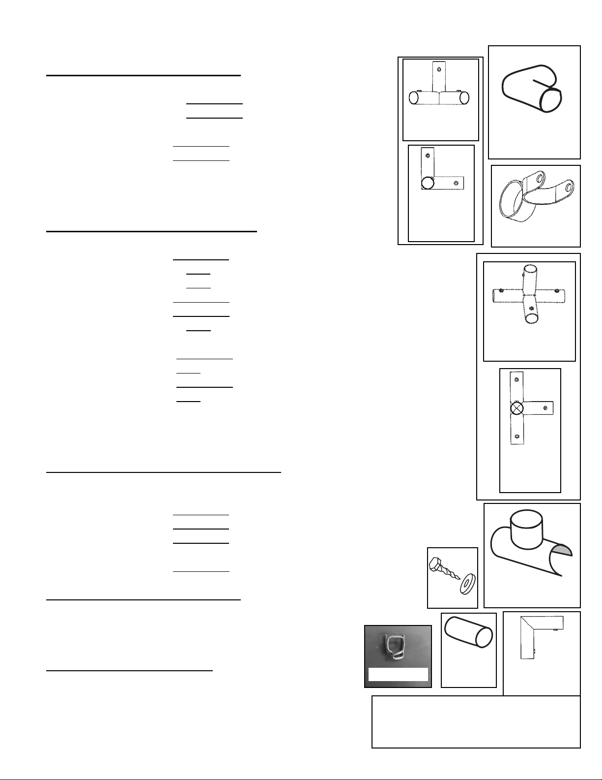
4-way
Metal-T
(Top View)
4-way
Metal-T
90°
Metal Elbow
Metal Ring
Metal
Corner Post
Metal
Corner Post
(Top View)
Banding Clip
1” Screws
PVC Snap-T
PVC Elbow
2” PVC
Nipple
Page 4 12’ Garden Master (3.5mm)
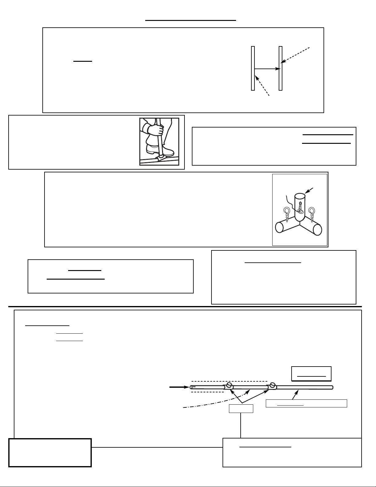
uuVery Important!! NEVER glue
the underside of the Snap-T. You
need to be able to slide the Snap-T
along the pipe. You only glue tubes
into the enclosed arm
F.
uuNOTE: Attaching Snap-T’s
this way prevents pinched
fingers! Use a small pipe and
step on the Snap-T.
B.
uuNote: The 3-Way Metal Corner posts have a red mark
on the “dead end” arm. In order for all measurements to
be correct, the 3-Way Metal Corner Posts must be oriented
correctly on the Base Frame and on the End Wall Frames.
Follow lthe directions carefully about where the red arm is
pointing. Please look at these fittings and check out the
arm with the red marking.
D.
uuNote: Tubes that are double-slotted
have slots on each end. Single-slotted
tubes only have slots on 1 end.
All Slotted ends attach to Snap-T’s.
C.
uuPVC Pipe is White and flexable.
Composite Pipe is white with small gray
fibers throughout and will not bend.
E.
3-Way Corner Post
Post With
Red Marking
Center
of tube
“In” side of tube
uuNote: All measurements are taken from the “in”
side of one tube to the center of the other tube
so one person can easily take the measurement by
her/himself.
A.
1. SIDE WALLS
Pieces Required:
6 75” Composite Tubing - ORANGE
8 75” Composite Tubing - ORANGE (Single-Slotted)
30 Snap-T’s
1. Attach 1 Snap-T about 23” from the end of the 75” tube
and a second Snap-T about 48 ¼” from the end of the
tube. (Do this to all 14 tubes -
Both slotted and non slotted tubes)
2. On two of the non-slotted side wall tubes add a snap-T
between the two snap-T’s. You can adjust the snap-T’s in a later step.
Side Walls are used in step 7.
75” Composite Tubing - Orange
Make 14
22 ¾”
48 ¼”
Snap-T
Very Important!! NEVER glue the
underside of the Snap-T. You need to be
able to slide the Snap-T along the tube.
Slotted End
Step #2 is no longer
needed so it has been
deleted
Hints for Preassembly
12’ Garden Master (3.5mm) Page 5
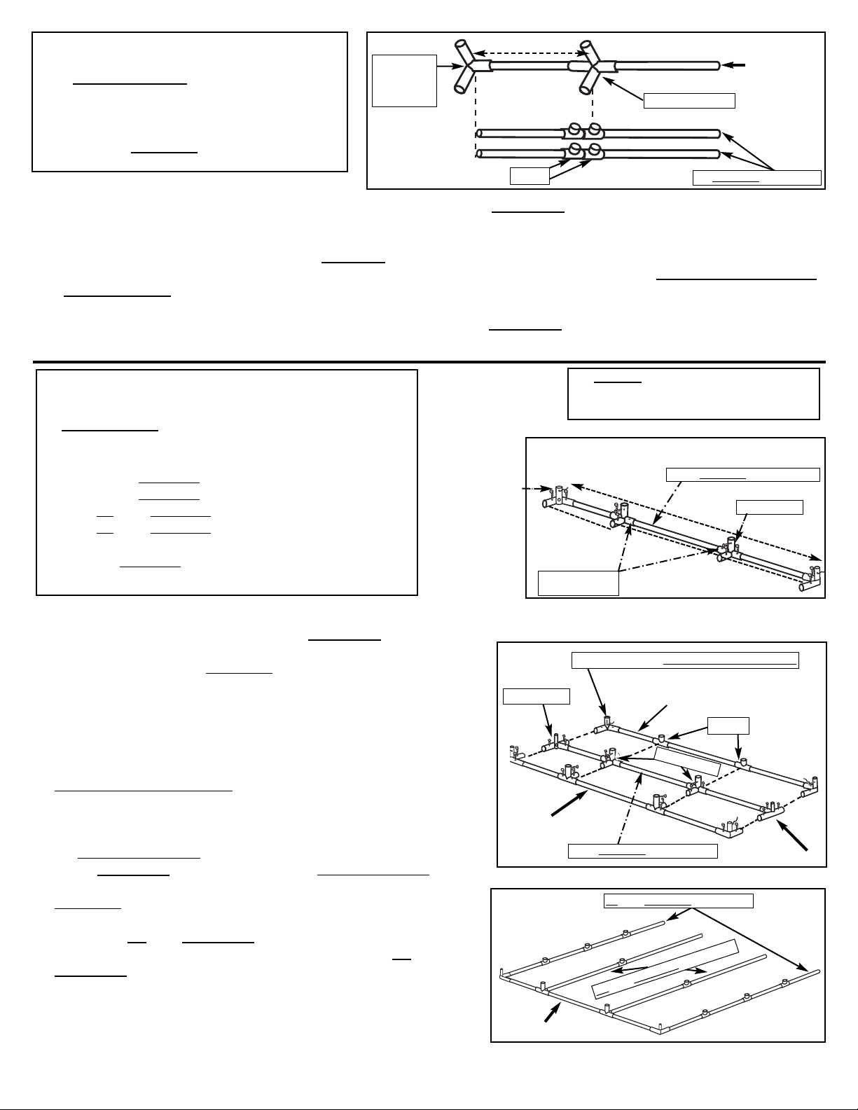
Making the 8’ Ridge Frames
Complete as shown on a level surface so the 8” Ridge Frames will be flat and not twisted. Ridge Frames are used in Step 7,
Side Walls and in Step 9, Top Ridge Assembly.
1. Insert 3-way 120° Metal Corner Post snugly on one end of a 92” Composite Tube - (Red) and twist
eyebolt until tight. (Insert a screwdriver or long bolt through the eyebolts and twist the eyebolt clockwise.)
2. Slide a 4-way 120° Metal-T over the 92” tube so that the distance from the “in” side of the 3-way 120° Metal Corner Post to
the center of the 4-way 120° Metal-T is 22 ¾”. Twist the eyebolts tight.
3. Slide over the 2nd 4-way 120° Metal-T so the distance from the inside of the 1st 4-way 120° Metal-T to the center of the
2nd 4-way 120° Metal-T is 22 ¾” - tighten. Slide over the 3rd 4-way 120° Metal-T so the distance from the inside of the
2nd 4-way 120° Metal-T to the center of the 3rd 4-way 120° Metal-T is 22 ¾” - tighten eyebolts
4. Repeat steps 1-3 twice for a total of three 8’ Ridge Frames.
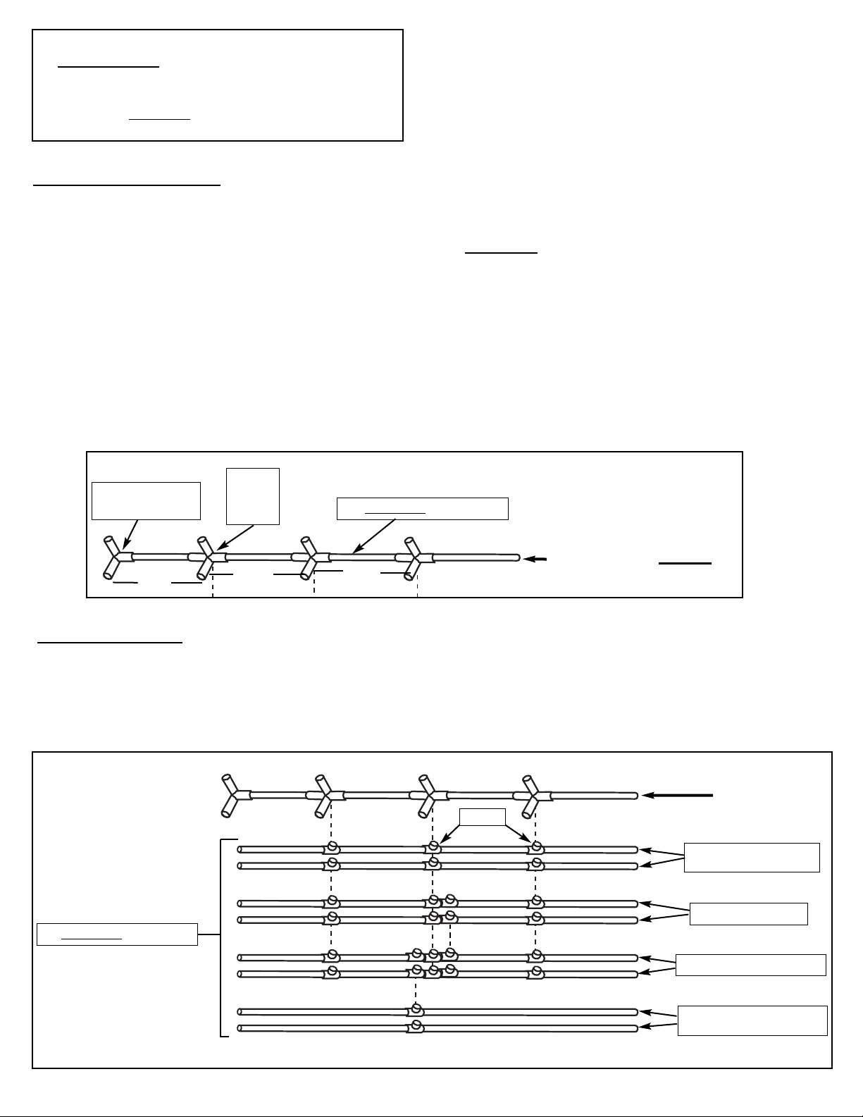
Aligning the Snap-T’s
5. Use a Ridge Frame to line up the Snap-T’s on the remaining 92” tubes. Follow the pattern below. Label the
tubes (BF, base frame; TB, top bench; BB, bottom bench; BS, Base Support) with a permanent marker to lessen
confusion about the tubes in later steps.
92” Composite Tubing - Red
4-way
120°
Metal-T
3-way 120° Metal
Corner Post
22 3/4” 22 3/4”
22 3/4”
8’ Ridge Frame (MAKE 3)
BF- Base Frame
TB- Top Bench
BS - Base Support
BB- Bottom Bench
92” Composite Tubes - Red
8’ Ridge Frame
BF
BF
TB
TB
BB
BB
BS
BS
Snap-T
3A. 8’ RIDGE FRAMES, BENCH & BASE RODS
Pieces Required:
9 4-way 120° Metal-T’s
3 3-way 120° Metal Corner Posts
11 92” Composite Tubing - RED
26 Snap-T’s
Page 6 12’ Garden Master (3.5mm)
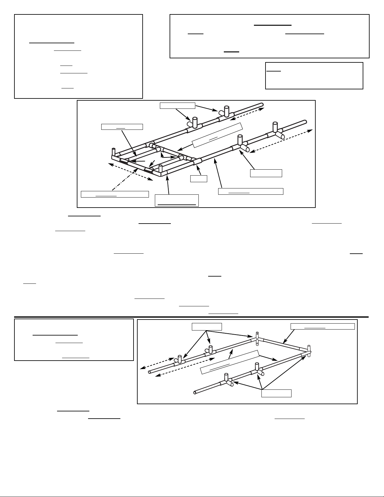
1. Slide two 4-way Metal-T’s onto a 94 ½” Composite Tube - Green.
Attach a Metal Corner Post (arm with the Red Mark is vertical)
to one end of the 94 ½” Composite Tube - GREEN and tighten the
eyebolt. Attach a 2nd Metal Corner Post to the opposite end and
adjust the Metal Corner Post so that the measurement from the “in”
side of one Corner Post to the center of the opposite Corner Post is
95 ¼”. Secure each 4-way Metal-T at 28 ¾” (“in” side to center) from
each Metal corner Post with eyebolts on the outside arms and 1”
Screws on the inside arms (see diagram 1 to the right). This is the
Front Base Frame Assembly.
2. Use the Front Base Frame assembly as a measuring device to line
up the fittings on the Middle and Back Base Frame Assemblies. On
the Middle Base Frame, attach four 4-way Metal-T’s onto the 2nd
94 ½” Composite Tube - Green. For the Back Base Frame, attach
two Metal Corner Posts and two Snap-T’s to the 3rd 94 ½”
Composite Tube - Green (see diagram 2 to the right).
3. Attach both BF- 92” Composite Tubes - Red to the Metal Corner
Posts of the Front Base Frame assembly. Attach both BS - 92”
Composite Tubes to the 4-way Metal-T’s of the Front Base Frame
assembly. (See diagram 3 to the right)
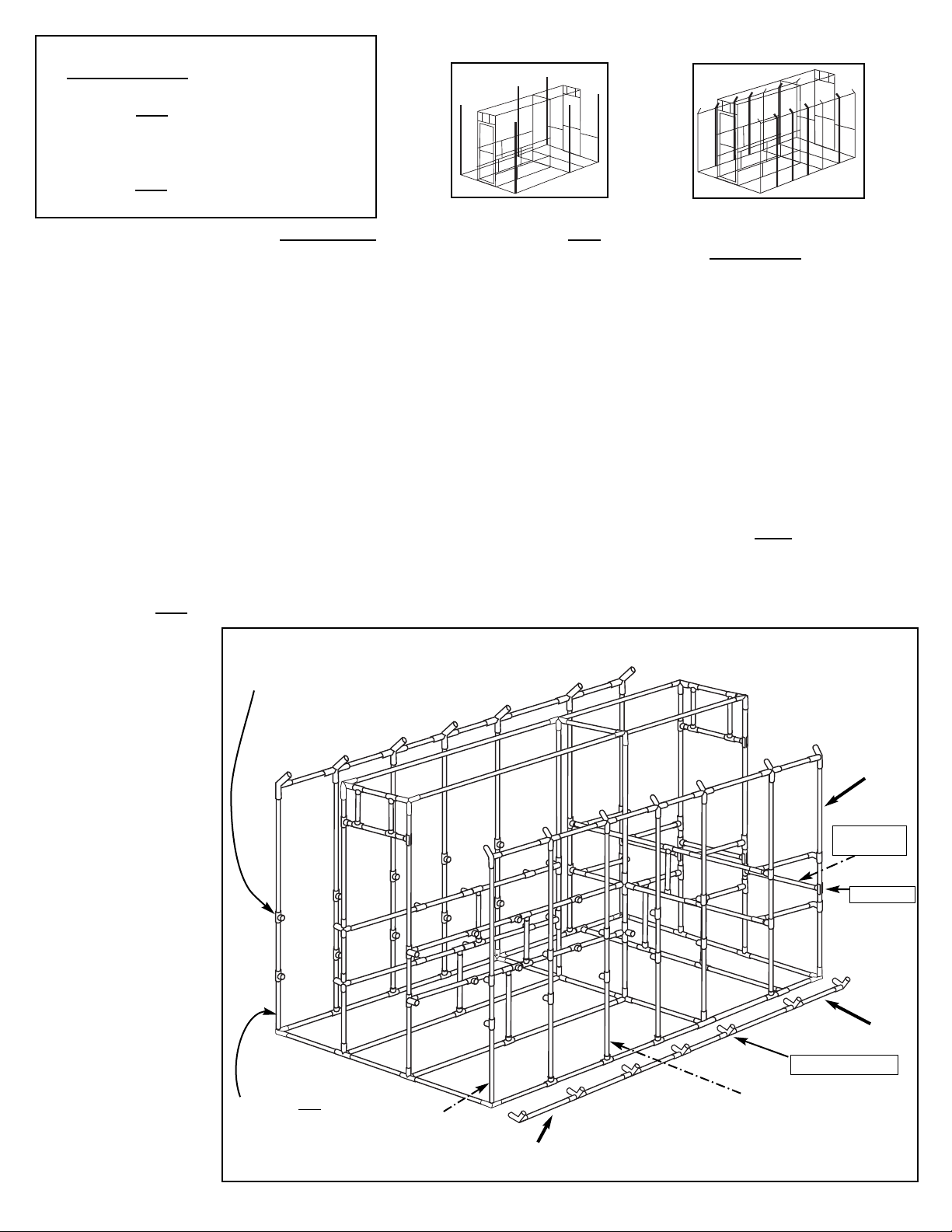
4. BASE FRAME
Make sure working surface is clean and level!
Pieces required:
4 Metal Corner Posts
6 4-way Metal-T’s
3 94 ½ ” Composite Tubing - GREEN
1 94 ½ ” Composite Tubing - GREEN (Double-Slotted)
2BF- 92” Composite Tubing - RED (from Step 3A)
2BS
- 92” Composite Tubing - RED (from Step 3A)
4 Snap-T’s
2 44” Composite Tubing - RED (from Step 3B)
2 1” Screws
Middle Base Frame
4-way Metal-T
4-way Metal-T
Metal Corner Post - Arm with red mark is facing up
Snap-T
Back Base Frame
3B. 4’ RIDGE FRAMES & BASE RODS
Pieces Required:
3 4-Way 120° Metal-T’s
3 3-Way 120° Metal Corner Posts
4 Snap-T’s
5 44” Composite Tubing - RED
1. Insert a 3-Way 120° Metal Corner Post snugly on one end of a 44” Composite Tube - Red and twist eyebolt until tight.
Insert a screwdriver or long bolt through the eyebolt and twist the eyebolt clockwise another ½ to full turn.
2. Slide a 4-Way 120° Metal-T over the 44” composite tube - Red so that the distance from the “in” side of the 3-Way 120°
Metal Corner Post to the center of the 4-Way 120° Metal-T is 22 5/8”. Twist the eyebolt tight. Repeat for a total of three
4’ Ridge Frames.
3. Use a 4’ Ridge Frame to line up the Snap-T’s on the remaining 44” Composite Tubes - Red. Follow the pattern above.
3-Way 120°
Metal Corner
Post 4-Way 120° Metal-T
Snap-T
(Make 3)
4’ Ridge Frames
44” Composite Tubing - Red
22 5/8”
NOTE: It is important that the
corner post is put on the right way.
(Red Mark is on the vertical arm)
28 ¾” 36 ½”
28 ¾”
95 ¼”
Metal Corner Post
(red mark on the
vertical arm) 4-way Metal-T
Remove eyebolt
Install 1” Screw
Front Base Assembly
94 ½” Composite Tubing - Green
94 ½” Composite Tubing - Green
Front Base Frame
Front Base Assembly
BS - 92” Composite Tubing - Red
BF - 92” Composite Tubing - Red
1.
2.
3.

12’ Garden Master (3.5mm) Page 7
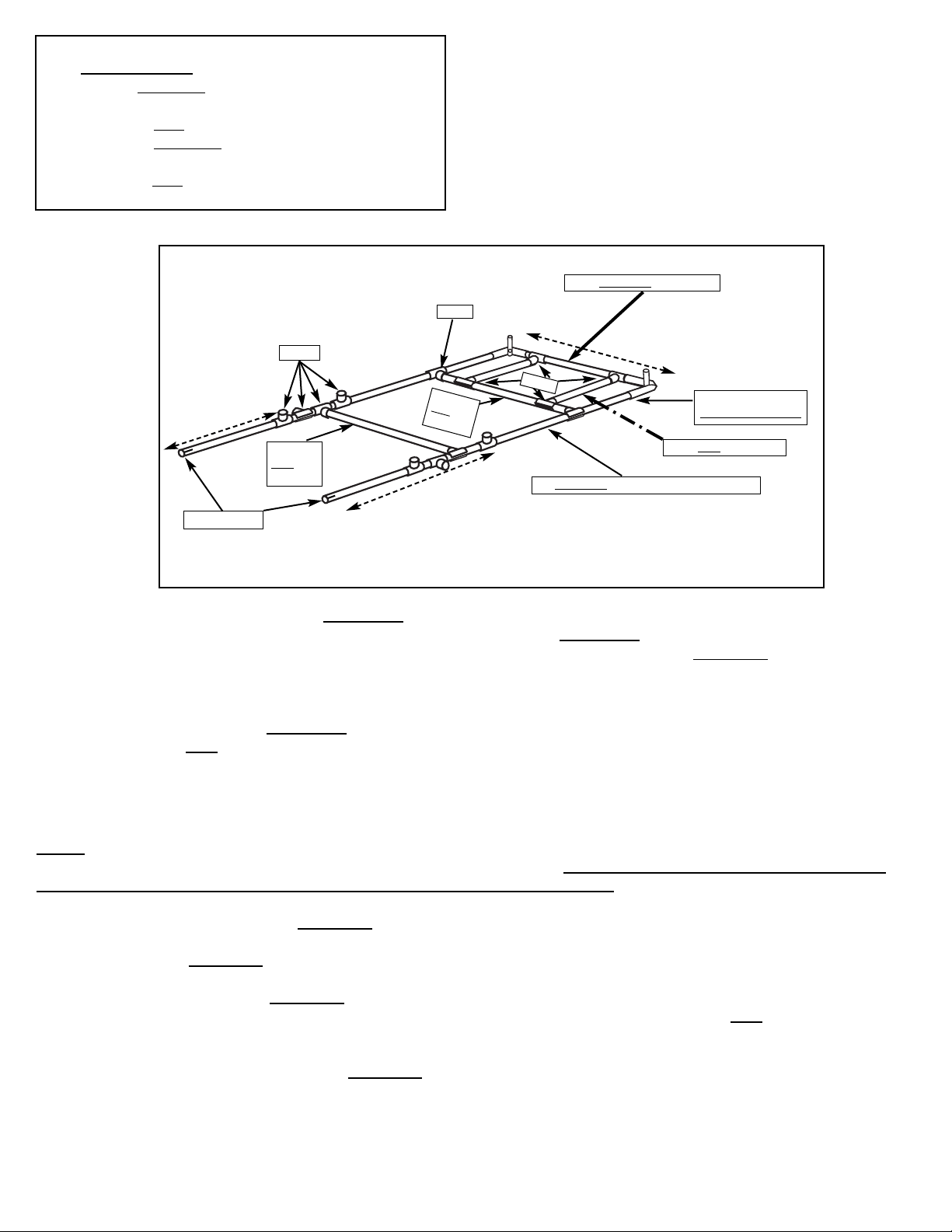
4. Attach the fittings of the Middle Base Frame assembly (made in step 3B-2) to the open ends of both BF - 92” Composite
Tubes - RED and both BS - 92” Composite Tubes - RED.Push both BS - 92” Composite Tubes - RED all the way into the
4-way Metal-T’s. Adjust the middle base frame assembly so that the measurements from the “in” side edge of the Front
Base Assembly to the center of the Back Base Assembly is 92 ¾”.
5. Attach both 44” Composite Tubes - Red (with Snap-T’s from Step 3B-3) to the 4-way metal-T’s on the ends of the
Middle Base Frame.
6. Attach the Metal Corner Posts of the Back Base Frame assembly to the opposite ends of the 44” Composite Tubes - Red
that you just added in the step above (Step 4-5). Making sure the arm with the red mark is facing up on the metal corner
posts. Adjust the Back Base Frame Assembly so that the measurement from the 94 ½” Composite Tube of the Middle Base
Frame Assembly to the 94 ½” Composite Tube of the Back Base Frame Assembly is 44 ¼” from “in” side to center. Tighten
the eyebolts.
7. Attach a 94 ½” Composite Tube - Green (Double-Slotted) into the Snap-T’s on the 44” Composite Tubes (added in Step
4-5) that are closest to the Back Base Frame Assembly. Use glue to help lubricate the tube to make it easier to slide
into the Snap-T’s. The glue does not adhere to the CompositeTubing, so you will have to secure the tubing by
drilling a screw through the top of the Snap-T and into the 94 ½” Composite Tube. Attach two Snap-T’s on to the
94 ½” Composite Tube - Green. Line up the Snap-T’s with the Snap-T’s that are on the Back Base Frame assembly.
CONT..... BASE FRAME
44” Composite Tubing - Red
Snap-T
Snap-T
Back Base Frame
Middle Base Frame
44 1/4”
(“In” side to center)
Corner Post with red
mark pointing up
BF- 92” Composite Tubing - Red
Middle Base Assembly
FRONT
SIDE
SIDE
BF- 92” Composite Tubing - Red
95 ¼” (“In” side to center)
BS - 92” Composite Tubing - Red
92 ¾” (“In” side to center)
4-Way Metal-T
BS - 92” Composite Tubing - Red
4-Way Metal-T
94 ½” Composite Tube
Green (Double-Slotted)
Snap-T
Page 8 12’ Garden Master (3.5mm)
5. END WALL FRAMES
5A. Front End wall Frame
Pieces Required:
2 90” Composite Tubing - YELLOW
2 Metal Corner Posts
1 35 ¾” PVC Pipes. - WHITE
1 35 ¾” Composite Tubing - WHITE
6 Snap-T’s
2 12 ½ ” PVC pipes -WHITE
4 4-Way Metal-T’s
5B. Middle End wall Frame
Pieces Required:
2 90” Composite Tubes - YELLOW
6 4-Way Metal-T’s
1 35 ¾” Composite Tube - WHITE
1. Slide a 90” Composite Tube - yellow snugly into a 4-way Metal-T (As pictured above) and tighten the eyebolt. Do this
twice. Attach a 35 ¾” Composite Tube - White between the 4-way Metal-T’s on the 90” Composite Tubes - yellow.
Measure the distance between the two 4-way Metal-T’s and adjust them so they are 36 1/2” from “in” side to center.
Tighten the eyebolts.
2. Slide two 4-way Metal-T’s on to each 90” Composite Tube - yellow (Note the direction of the posts pictured above).
Tighten the eyebolts of the the top 4-way metal-T so the distance from the center of the middle arm to the bottom of the
90” composite tube - yellow is 48 ¼” and the distance from the center of the middle arm of the bottom 4-way metal-T to the
bottom of the 90” composite tube - yellow is 22 ¾”.
35 ¾” Composite Tubing -White
4-way Metal-T
uuBe sure to get the composite tubing and the
PVC pipe in the right spot. Composite tubing
has a gray fiber throughout and does not flex.
While the PVC is white and flexable
Note: On Metal Corner Posts, the
Arm with red mark attaches
to 90” Composite Tube.
35 3/4” PVC pipe - White
90” Composite Tubing - Yellow
35 ¾” Composite Tubing - White
Snap-T
4-way Metal-T
Metal Corner Post
(arm with red mark)
12 ½” PVC - White
22 ¾”
48 ¼”
36 1/2”
Snap-T
4-way Metal-T
1. Slide each 90” Composite Tube - Yellow snugly into a Metal Corner Post (insert tube into the arm with the red mark)
and tighten the eyebolt. Attach a 35 ¾” Composite Tube between the Metal Corner Posts on the 90” Composite Tubes.
Adjust 90” Composite Tubes (With metal coner posts on them) so the distance between the Metal Corner Posts is 36 ½”
from “in” side to center - tighten the eyebolts.
2. Attach a Snap-T on to both 90” Composite Tubes about 13” below the Metal Corner Posts. Insert and glue a 35 ¾” PVC
pipe between these Snap-T’s.
3. Attach two Snap-T’s to both 35 ¾” pipes. Attach and glue 12 ½” PVC pipes between the Snap-T’s. Slide over each 12½”
PVC pipe - white (With snap-Ts attached) to the edge of the Metal Corner Posts.
4. Slide two 4-way metal-T’s on both 90” Composite Tubes - yellow (Note direction of the posts). Tighten both bottom 4-way
metal-T’s so they are 22 ¾” from the bottom of the 90” Composite Tube - yellow to the center of the fitting. Tighten both
top 4-way metal-T’s so they are 48 ¼” from the bottom of the 90” Composite Tube - yellow to the center of the fitting.
90” Composite Tubing -Yellow
4-way Metal-T
22 ¾”
48 ¼”
12’ Garden Master (3.5mm) Page 9
1. Slide the non-slotted end of each 90” Composite Tube - Yellow (Single-Slotted) into a Metal Corner Post (Insert tube
into the arm with the red mark) and tighten the eyebolt. Attach a 35 ¾” Composite Tube - White between the Metal
Corner Posts attached to the 90” Composite Tubes - Yellow (Single-Slotted). Adjust the 90” Composite Tubes with the
metal corner posts attached so the distance between the Metal Corner Posts is 36 ½” from “in” side to center. Tighten
the eyebolts.
2. Attach a Snap-T to each 90” Composite Tube - Yellow (Single-Slotted) , about 13” below the Metal Corner Post. Insert
and glue a 35 ¾” PVC pipe - White between these Snap-T’s.
3. Attach two Snap-T’s on to both 35 ¾” pipes. Attach and glue a 12 ½” PVC pipe - White between these Snap-T’s. Slide
each 12 ½” pipe (With snap-t’s attached) over so it is 10 ½” from the “in” side of the 90” tube to the center of the 12 ½” pipe
(leaving about 13 ½” between the 12 ½” pipes).
NOTE: This spacing applies when installing a 12” Exhaust Fan. If installing a 16” fan or larger, replace the 12 ½” pipes with
the larger pipes included with the fan (refer to Fan installation instructions). If a Fan was not purchased, slide over both
12 1/2” pipes (with snap-T’s attached) to the edge of the Metal Corner Posts.
4. Attach two Snap-T’s on each 90” Composite Tube - Yellow (Single-Slotted). The center of the top Snap-T is at 48 ¼” from
the bottom of the 90” composite tube - Yellow (Single-Slotted) and the center of the 2nd Snap-T is at 22 ¾” from the
bottom of the 90” Composite Tube - Yellow (Single-Slotted).
5. Attach a Snap-T on each 90” Composite Tube - Yellow (Single-Slotted) between (Approximately - it can be adjusted later)
the top and bottom Snap-T’s attached in the previous step (Step 5C-4). Insert and glue a 35 ¾” PVC pipe - White into
these Snap-T’s.
6. Attach an additional Snap-T on each 90” Composite Tube - Yellow (Single-Slotted) below the Snap-T you just put on in
step 5C-5.
5C. Back End wall Frame
Pieces Required:
2 90” Composite Tubes - YELLOW (Single-Slotted)
2 Metal Corner Posts
2 35 ¾” PVC Pipes. - WHITE
1 35 ¾” Composite Tubing - WHITE
14 Snap-T’s
2 12 ½” PVC pipes - WHITE
35 ¾” Composite Tube - White
90” Composite Tube -Yellow (Single-Slotted)
12 ½” PVC pipe - White
Snap-T
Metal Corner Post
(Arm marked with red)
22 ¾”
48 ¼”
35 ¾”
PVC pipe
White
35 ¾”
PVC pipe
White
Slotted end
Snap-T
Snap-T
36 ½”
Page 10 12’ Garden Master (3.5mm)
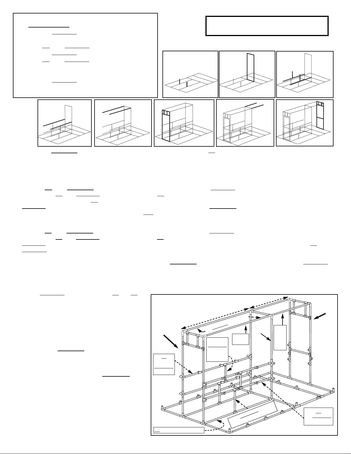
1. Attach a 22” Composite Tube - White (Double-Slotted) into the Snap-T’s on Both BS - 92” Base Frame tubes. Secure tubing into the
Snap-T’s with a 1” Screw. See diagram 1 above.
2. Attach Middle End wall to the 4-way Metal-T’s on the Middle Base Frame and tighten the eyebolts. (The Lower and middle 4-way
metal-T’s face towards the front base assembly. See diagram 2 above and diagram below.)
3. Insert the BB - 92” Composite Tubes into the bottom 4-way Metal-T’s on the 90” Composite Tubes - Yellow (Middle End wall). Attach
the end of the BB - 92” composite tubes that were marked BB from step 3A-5, into the post and tighten the eyebolts. There are 3
snap-T’s on the middle of the BB tubes, of these three snap-T’s, join the snap-T that is farthest from the Middle end wall onto the 22”
composite tube - white (Double-Slotted), from Step 6-1 above. Next, attach a 24” Composite Tube - Orange (Double-Slotted) into
the Snap-T that is closest to the Middle end wall (on both BB - 92” Composite tubes). Secure all Snap-T’s to the tubes with 1” Screws.
See diagram 3 above and diagram below.
4. Insert the TB - 92” Composite Tubes into the Middle 4-way Metal-T’s on the 90” Composite Tubes - Yellow (Middle End wall). Attach
the end of the TB - 92” composite tubes that were marked TB from step 3A-5, into the post and tighten the eyebolts. Attach the 24”
composite Tubes - orange (Double-Slotted) to the Snap-T’s (That are right of center - Closest to the middle end wall) on both TB - 92”
Composite Tubes. Secure them with1” Screws. See diagram 4 above and diagram below.
5. Use a marker and draw a line 2 ¾” in from both ends of the 92” Composite Tubes - Red (Do this on both tubes). Put 92” Composite
Tubes - red into the top 4-way metal-T’s on the Middle End Wall. Slide tubes into the posts until the line you just marked on them is even
with the post and tighten the eyebolts. See diagram 5 above and diagram below.
6. Lift and attach the Front End wall to the 4-way Metal-T’s on the Front Base Frame and tighten the eyebolts. Insert the opposite sides of
the 92” Composite Tubes (Including all TB and BB
assemblies) into the corresponding Metal Fittings and
tighten the eyebolts.
Check the measurements of the Hanging Rods.
They should be 92 ¾” from the “in” side of one 35 ¾”
Middle End Wall tube to the center of the 35 ¾” Front
End wall tube. See diagram 6 and diagram to the right.
7. Insert both 44” Composite Tubes - Red into the 4-way
Metal-T’s at the top of the Middle End Wall. See
diagram 7 and diagram to the right.
8. Attach the Back End Wall (Insert slotted end
completely into the Snap-T’s on the Back base frame.
Use glue to help lubricate the tube to make it easier to
slide into the Snap-T’s. The glue does not adhere to
the Composite Tubing, so you will have to secure the
tubing by drilling a screw through the top of the
snap-T and into the 90” Composite Tubes.
Insert the opposite ends of the 44” Composite Tubes into
the Metal Corner Posts at the top of the Back End Wall.
The measurement from the “in” side of the 35 ¾” Middle
End wall tube to the center of the opposite 35 ¾” Back
End Wall tube should be 44 ¼”
6.
6. HANGING RODS & BENCH RODS
Pieces Required:
2 22” Composite Tube - White (Double-Slotted)
1 Middle End wall (from Step 5B)
2 BB - 92” Composite Tube - RED (from step 3)
2 24” Composite Tube - Orange (Double-Slotted)
2 TB - 92” Composite Tube - RED (from step 3)
2 92” Composite Tube - RED
1 Front End wall (from Step 5A)
2 44” Composite Tube - Red
1 Back End wall (from Step 5C)
8 1” Screws
1. 2. 3.
4. 5. 7. 8.
Two people & ladder recommended!
Hanging
Rod
Front
End Wall
44 ¼”
Middle
End wall
92” Composite Tubing - Red
92 ¾”
Back
End wall
24”
Composite
Tubing
(Double
Slotted)
TB
92”
Composite
Tubing
22” Composite Tubing
white (Double-slotted)
BB
92” Composite
Tubing
BS - 92” Base Frame Tube
44”
Com-
posite
tube
Red
12’ Garden Master (3.5mm) Page 11
1. Locate the 6 Side Wall tubes (without slots - From step 1). Slip an 18” PVC pipe -½” diameter into the center (bottom) of
the Side Wall Tube (It sits loose inside of the tube) and then insert the side wall tube into the Metal Fitting on the base
frame (Do this for all six side wall tubes - with out slots. Insert the two Side Wall tubes with the extra Snap-T on it, into the
Corner Posts on the Back Base Frame. Tighten the eyebolts. Draw a line 2 ¾” down from the top of the corner side wall
tubes. Do this on all four corner side wall tubes.
2. Use a 1” Screw to attach the 8 remaining Side Wall tubes (Single-Slotted) into the Snap-T’s on the BASE FRAME. Make
sure the Side Wall tubes are seated all the way into the Snap-T’s. Adjust the Snap-T’s on the side wall tubes so they
face towards the inside of the greenhouse.
3. Line up an 8’ Ridge Frame with the 8’ base frame of the greenhouse. Make sure the Snap-T’s and Metal fittings on the
base frame are lined up with the Metal Fittings of the 8’ Ridge Frame. Add a 4-way 120° metal-T to the end of the 8’
Ridge Frame and tighten the eyebolt. Insert the 4’ Ridge Frame into the opposite end of the 4-way 120° metal-T making
sure that the metal fittings on the 4’ ridge frame line up with fittings on the base frame that the side wall tubes go into.
tighten the eyebolts. Repeat this step to make two 12’ Side Ridge Frames.
4. Place the Metal fittings of a Ridge Frame onto the top of the Side Wall tubes. Tighten the eyebolts. Note: On the corner
Side Wall tubes, move the ridge frame up or down so the arm of the 3-way 120° Metal Corner Post lines up with the line
drawn on the Side Wall tubes in step 7-1 above. Repeat this step for the other side wall.
5. Attach a 28” PVC pipe - Green between the Snap-T’s (B) on the Back End wall and Back Side Wall tubes. See diagram
below.
Adjust all the Snap-T’s on the side
wall tubes to face towards the
inside of the greenhouse.
Snap-T (B)
7. SIDE WALL ASSEMBLY
Pieces required:
14 Side Walls (Made in step 1)
2 28” PVC pipes - Green
2 8’ Side Ridge Frames (from Step 3A)
2 4’ Side Ridge Frames (from Step 3B)
2 4-Way 120° Metal-T
6 18” PVC pipe - ½” diameter
8 1” Screws
28” PVC pipe
Green
Side Wall
tube with
extra Snap-T
8’ Side Ridge Frame
4-Way 120° Metal-T
4’ Side Ridge Frame
Composite drawing for Steps 7 & 8A
Slotted end goes into the Snap-T.
Secure 74” tube with 1” Screw
Insert an 18” PVC pipe - 1/2” diameter into the
Side Wall Tubes that go into metal fittings.
This pipe provides support when
attaching the anchor kit (If purchased) to the
greenhouse.
1. 2.

Page 12 12’ Garden Master (3.5mm)
8A. BACK BENCH ASSEMBLY
Pieces Required:
2 94 ½” Composite Tubing - Green (Double-Slotted)
10 22” Composite Tubing - White (Double-Slotted)
1 24” Composite Tubing - Orange (Double-Slotted)
12 Snap-T’s
4 PVC Elbows
4 PVC Nipples
38 1” Screws
MAKE 4
22” Composite Tubing - White (Double-Slotted)
PVC Elbow PVC Nipple
Bench Assembly with Elbow:
1. Insert a PVC Elbow onto a 22” Composite Tube - White (Double-Slotted). Secure with a 1” Screw.
2. Insert and glue a PVC Nipple into the PVC Elbow. Repeat these two steps to make a total of 4 bench assemblies (with
elbow). See diagram to the upper right.
3. Attach two 22” Composite Tubes - white (Double-Slotted) into the Snap-T’s on the 94 ½” Composite Tube - green
(Double-Slotted). The base frame tube added in step 4 - 7. Attach a Snap-T to the top of the 22” Composite Tubes - White.
(Double-Slotted). Secure with 1” Screws. These tubes will support the bench pipes.
4. Attach five Snap-T’s to a 94 ½” Composite Tube - Green (Double-Slotted). See diagram A below and space the snap-Ts
approximately as shown. They can be adjusted as you assemble. Insert this tube into the bottom Snap-T’s on both Ribs #6
Secure with 1” screws.
4a. Glue the 2” Nipple of a Bench Assembly With Elbow into the bottom Snap-T on Rib 7. Attach the other end of the Bench
Assembly to a Snap-T on the 94 ½” Composite Tube - green (Double-Slotted) bottom bench rod as shown in diagram A.
Repeat for the opposite side. Attach a 22” Composite Tube - White (Double-Slotted) between the bottom Snap-T’s on
the Back End Wall and the Snap-T’s on the 94 ½” bottom bench rod. Snap these 22” tubes into the Snap-T’s on the vertical
22” Composite Tubes you installed in step 8A-3 above.
5. Attach a 24” Composite Tube - Orange (Double-Slotted) to the remaining center Snap-T on the 94 ½” bottom bench rod
installed in step 8A-4 above. Attach five Snap-T’s to the remaining 94 ½” Composite Tube - Green (Double Slotted)and
insert the tube into the top Snap-T’s on both Ribs #6. Secure with 1” Screws. Attach the 24” Composite Tube to the center
Snap-T on the top 94 ½” Composite Tube - Green (Double-slotted) - Upper bench rod.
6. Repeat Step 8a-4a (above) for the top bench, except you will use the upper snap-T’s on ribs 6 & 7. Secure all Snap-T’s to
the tubing with 1” Screws.
7. Adjust Bench Frame pipes by sliding the Snap-T’s on the Ribs up or down, so that the Snap-T’s of each bench frame are at
an equal height. HINT: Use a rubber mallet to tap the
pipe up or down. After everything is level, attach a 1”
screw through the “snap” portion of the Snap-T’s on the
side walls and end walls to prevent the shelf tubes from
sliding down.
3.
5.
4.
6.
Bench
Assembly
with Elbow
Side Wall (Rib) 6
Side Wall (Rib) 7
Side Wall
(Rib) 6
Side Wall (Rib) 7 Back End Wall
22” Composite Tubing
White (Double-Slotted)
24” Composite Tubing
Orange (Double-Slotted)
94 ½” Composite Tubing
(Double-slotted) Bench Rods
Bench Assembly with Elbow
22”
Composite
Tubing
(White)
Double-
Slotted
A.

12’ Garden Master (3.5mm) Page 13
Attach
1” Screws
8B. BENCH ASSEMBLY
Pieces Required:
20 28” Composite Tubing - GREEN (Double-Slotted)
42 1” Screws
92” Composite Tubing - Red
(Bench Rod)
28” Composite Tubing -Green
(Double-Slotted)
BB - 92” Composite Tubing - Red
(Bench Rod)
Attach screw here
(See picture below)
4-way Metal-T
22 ¾”
48 ¼”
28” Composite Tubing -Green (Double-Slotted)
Snap-T
1” screw
Top of Snap-T
Composite Tube
1. Insert eight 28” Composite Tubes - Green (Double-Slotted) into the 4-way Metal-T’s that are on the end walls. Attach
the opposite ends of the 28” Composite Tubes - Green (Double-Slotted) into the snap-T’s on the corner side wall tubes.
(NOTE: The glue does not adhere to the Composite Tubing. Apply glue around the outer end of the pipe and inside
the top of the Snap-T fitting for lubrication. The tubing will be easier to slide into the Snap-T’s.) You will need to
secure the tubing by putting a 1” Screw through the top of the Snap-T and into the 28” Composite Tubes - Green
(Double-Slotted) - See picture below. Attach the remaining 28” Green Composite Tubes between the Snap-T’s on the rib
pipes and the Snap-T’s on the 92” Bench Rods using glue to lubricate and 1” Screws to secure.
2. Double check measurements and make sure that the 4 -way Metal-T’s on the End walls are at 22 ¾” and 48 ¼” from the
top of the BS - 92” Base Frame Tube to the center of the fitting. (See diagram above)
3. Adjust Bench Frame tubes (by moving Snap-T’s on the Ribs up or down) so Snap-T’s of each bottom bench frame
are at an equal height and level with each other. HINT: Use a rubber mallet to tap the snap-T up or down.
4. After everything is level on the bench frames, attach a 1” Screw through the top of the vertical Snap-T’s on the Side Wall
Tubes to prevent shelf brackets from sliding down (See picture below).
Page 14 12’ Garden Master (3.5mm)
A. B.
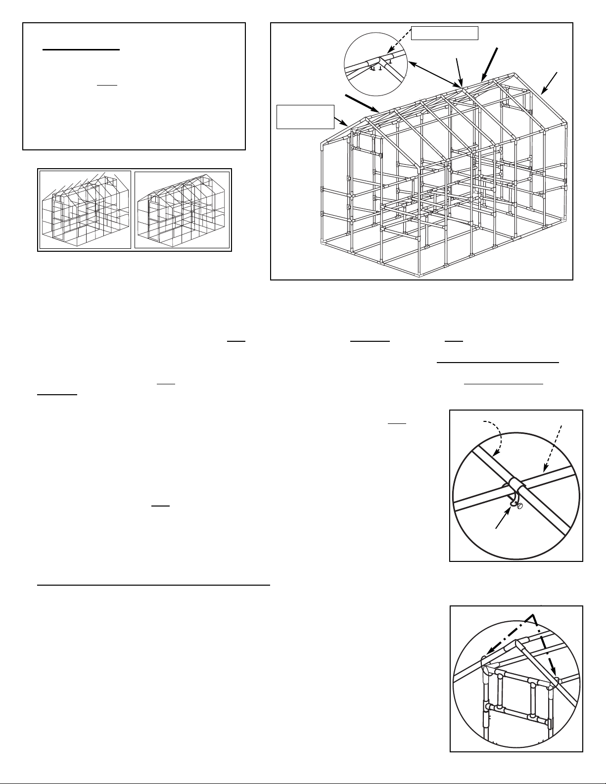
1. Line up the 8’ Top Ridge Frame with the 8’ base frame of the greenhouse (see picture Step 7). Make sure the Snap-T’s and the metal
fittings on the base frame are lined up with the metal fittings of the 8’ Top Ridge Frame. Add a 4-way 120° Metal-T to the end of the 8’
Ridge Frame and tighten the eyebolt. Insert the 4’ Top Ridge Frame into the opposite end of the 4-way 120° Metal-T. Line up the metal
fittings of the 4’ Top Ridge Frame with the Side Wall tubes and tighten the eyebolt of the 4-way 120° Metal-T.
2. Draw a line 2 ¾” down from the end of a 54 ¼” PVC pipe - Yellow. Do this on both ends of six 54 ¼” PVC pipes - yellow. Set four 54 ¼”
pipes into the 3-way 120° Metal Corner Posts of the Side Ridge Frame (Rafters #1 & 7 - See diagram above) at the front and back of the
greenhouse and two 54 ¼” pipes into the 4-way 120° metal-T above the middle end wall (rafter #5). DO NOT tighten the eyebolts!!!
3. Set the remaining eight 54 ¼” PVC pipes - yellow into the 4-way 120° Metal-T’s of the Side Ridge Frames. DO NOT tighten the
eyebolts!!! - In the next step you will be pulling these tubes out of the side wall fittings and inserting them into the 12’ top ridge frame
fittings. Then you will attach the top ridge frame with the 54 ¼” tubes attached back into the side ridge frames to form the roof framing.
4. Balance the 12’ Top Ridge Frame on the hanging rods. Starting at rafter #1, pull a 54 ¼” PVC pipe -
yellow from the Side Ridge Frame and insert it into the arm of the 3-way 120° Metal Corner Post on the
12’ TOP RIDGE FRAME (54 ¼” pipe will pop out of the Metal Fitting on the side Ridge frame - this is
OK). Push the 54 ¼” pipe into the 3-way 120° Metal Corner Post (On the top ridge frame) until the line
you drew on it in step 9 - 2 is even with the arm of the 3-way 120° Metal Corner Post. Tighten the
eyebolt. Repeat on the opposite side and opposite end of the greenhosue, pulling the four corner 54 ¼”
pipes - yellow and inserting them into the 12’ Top Ridge Frame.
5. Pull out the remaining 54 ¼” PVC pipes - yellow and insert them into the remaining metal fittings on the
12’ Top Ridge Frame. Insert the 54 ¼” pipes - yellow all the way into the 4-way 120° Metal-T’s until
they stop. On rafter #5 & #7 push the 54 ¼” pipes in so the line you drew on it is even with the arm on
the post. Tighten the eyebolts.
6. Rest the top Ridge Frame and Rafter (54 ¼” pipe) assembly over the center of the Hanging Rods.
7. Insert the Rafters into the Metal Fittings of the side Ridge Frame one at a time. Slide a Metal Ring on Rafters #2, 3, 4 & 6.
Do not tighten the eyebolts until all the Rafters are in place. Once all Rafters are inserted into the metal fittings of the side Ridge
frames, tighten the eyebolts. Adjust Rafters on the front, middle and back end walls so the line drawn is even with the post of the fitting.
8. Slide the Metal Rings up to the Hanging Rods. Adjust the “U” bracket so it straddles the hanging rod.
Slide a 1 ½” x 3/16” machine screw through the bolt hole of the Metal Rings and attach a 3/16” wing
nut.
9. Attach a Zip Tie around the Rafter and Metal Corner Post at each end wall. Do this on Rafters #1, 5 &
7 - Front, middle and back end wall. See diagram to the right.
9. TOP RIDGE ASSEMBLY
Pieces required:
1 8’ Top Ridge Frame, made in step 3A
1 4’ Top Ridge Frame, made in step 3B
14 54 ¼” PVC pipes - Yellow
1 4-Way 120° Metal-T
8 Metal Rings
8 1 ½” x 3/16” Machine Screws
8 3/16” wing nuts
6 Large Black Zip Ties
Metal Ring
Rafter Hanging Rod
4-Way 120° Metal-T
8’ Top Ridge Frame
4’ Top Ridge Frame
54 ½” PVC pipe
(Rafter #1)
Zip Tie
Rafter #7
Rafter #5
12’ Garden Master (3.5mm) Page 15
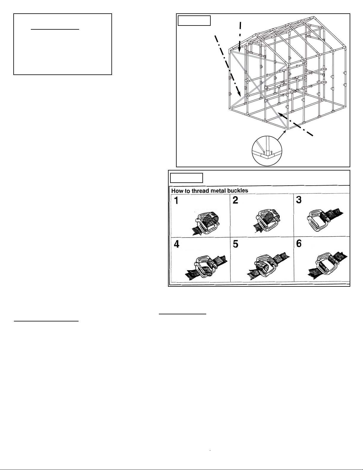
Banding 1
Banding 2
Banding 3
FIG 10A
1. On the front end wall, loop Banding 1 through an
eyebolt on the Metal Corner Post on the base frame.
Loop the other end of the banding through an eyebolt
on the opposite 3-Way 120° Metal Corner Post on the
Side Ridge Frame.
2. Thread banding through the metal buckle as
shown/explained in Fig 10B.
3. Thread Banding 2 to the opposite diagonals.
4. Tighten Banding 1 & 2 so the diagonals are equal in
length. If they are not equal in length. Lossen the
shorter one and then tighten the longer band until the
two diagonal measurements are the same.
5. Loop Banding 3 through an eyebolt of the 3-way
120° Metal Corner Post of one Side Ridge Frame to
the eyebolt of the 3-way 120° Metal Corner Post on
the opposite Side Ridge Frame. Tighten the banding
so the measurement from the “in” side of one 3-way
120° Metal Corner Post to the center of the opposite
3-way 120° Metal Corner Post is equal to 95 ½”.
Keep banding in place until Front End wall paneling has
been applied.
10 A. SQUARING FRAME
Pieces Required:
3 Yellow Banding
3 Metal Banding Clips
2 76” Side Door Casing
(1 with hinges)
1 38” Top Door Casing
1 1” Screw
How to thread Metal Buckles
1. Form a 3” loop by folding banding away from you,
(short end of banding needs to be on top). With
buckle tines facing upright, pass loop up through
center of buckle.
2. Slip the loop over the tine (farthest from you).
3. Pull banding down and away.
4. Place banding around specified frame area. Fold a
new loop by folding banding toward you.
5. Slip new loop over other tine.
6. Tension by pulling banding coming from coil.
7. To loosen banding, grasp coil with pliers and twist
your wrist so banding slides loose from tine.
NOTE: Measure
the diagonals with
a tape measure
first. If diagonals
are equal, skip
step 10A.
10 B. Sizing Door Frame for Door Casing
1. Using the Top Door Casing as a measuring device, check to make sure
the door opening is 36 7/8” at both the top and bottom from “in” side to
center of the 90” tubes.(The Top Door Casing fits between the snap-T’s
on the top of the 90” tubes.)
2. Make sure the door opening is square by measuring diagonally from
corner to corner and making sure the measurements are the same. Also
check that the 90” tubes are plum (Straight up and down) and the top door
frame tube is level.
3. Again place the Top Door Casing over the 35 3/4” tube. Hold in place
temporarily with one screw inserted from the front and into the tube.
4. Temporarily place the side Door Casing with the Hinge attached on
whichever side you want your door to hinge from.
5. Place the other Side Door Casing on the opposite side of the door
opening. All 3 Door Casing pieces should fit snugly.
6. Remove the Door Casing Pieces. They will be used in the Door
Assembly Step #14. Proceed with paneling.
FIG 10B
Page 16 12’ Garden Master (3.5mm)
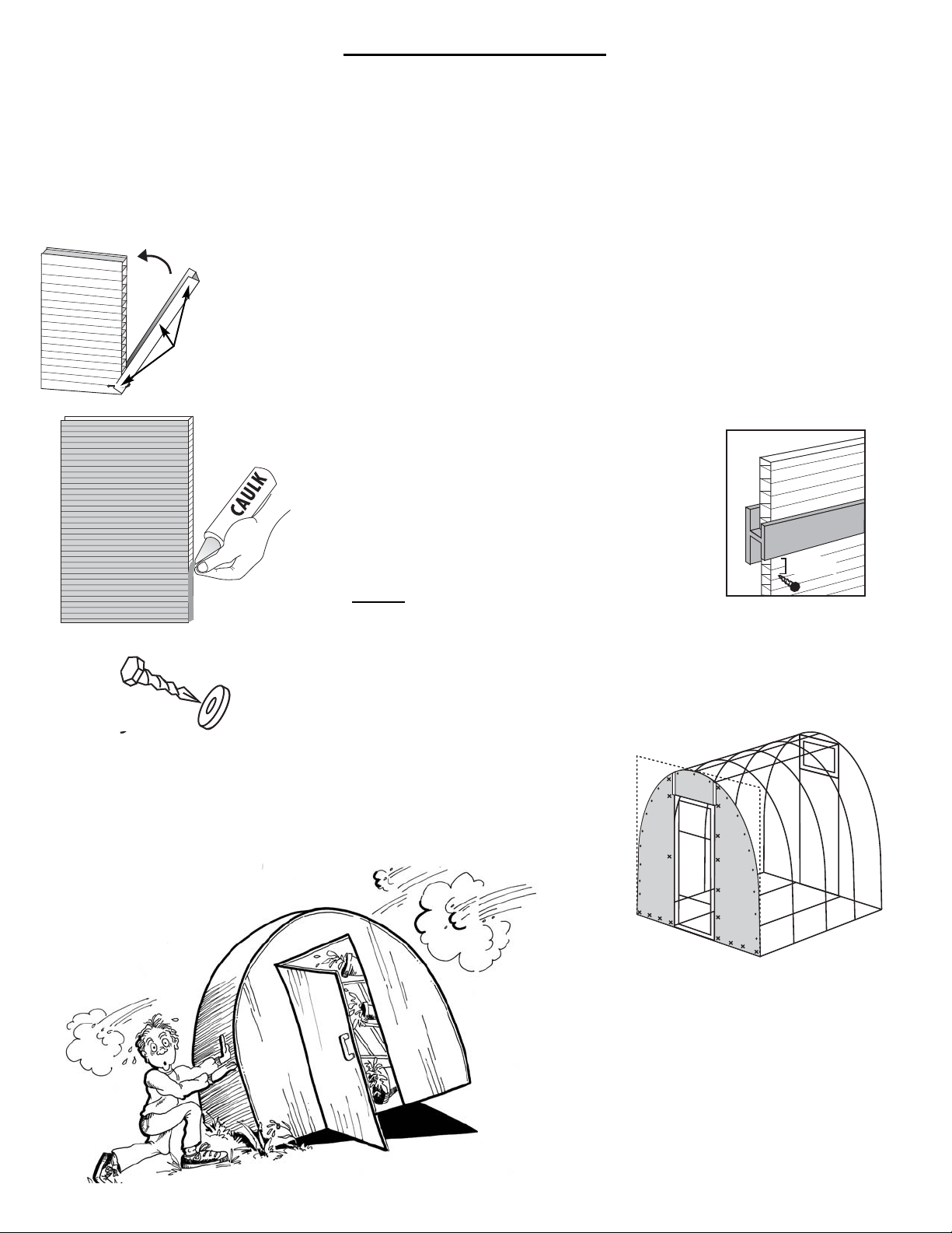
Hints for Panel Assembly
Congratulations, your frame is now finished! All that’s left is the paneling application. Listed are
several hints that will make paneling your greenhouse much easier. If you have suggestions that
would be helpful for future customers we would be happy to hear from you.
1. PANELS: Apply paneling when temperature is moderate for your area (not during a cold or hot spell). When attaching
panels to the PVC tubing, be careful not to over-torque the screws. The washers should just make a dimple in the panel.
The screws should be placed about 12” - 15” apart on the panels and about 6” apart around the perimeter of the walls, roof
and any overlapped joint.
2. U-TRIM: Insert ¼” - ½” of 100% silicone caulking into open flutes to prevent water intrusion.
Place U-Trim over the 4’ ends of panels where specified in the instructions. Secure the U-Trim
with small Phillips Screws by poking a small pilot hole in the U-trim and screwing through
the U-Trim and into the panel. Use about 3 or 4 Screws per U-Trim
uNote: When using caulking, cut tip of tube at an angle. Be careful not to get caulking
on nice clothing or jewelry.
3. H-CHANNEL: If H-Channel is difficult to slide on,
spray panel edges with Pam (Vegetable oil). Also
tapping on ends of H-Channel with a rubber mallet
helps H-Channel slide on easily. Secure panels by
placing screws into pipes 2 ½” from each side of the
H-Channel. You can cut H-Channel by scoring on both
sides with a knife and then bending at the score or use
tin-snips.
NEVER attach screws into the H-Channel!
4. SCREWS: Use the pictures as a guide for placement of screws. Use your
discretion on your own greenhouse. The number of screws required for each
step in paneling may not exactly coincide with the picture.
5. CUTTING PANELS: Panels cut very easily with a long, thin sharp
knife or utility knife. Use the Frame or a straight edge for a guide when
trimming panels.
6. TIE DOWN: Please remember to tie down
your greenhouse once you begin paneling.
The greenhouse is light enough that on a
windy day it could blow over.
2 1/2"
Small
Phillips
Screw

1. Caulk the open flutes on one end of all three of the panels.
2. Screw the two 31” x 94 ½” Panels into place (caulked end
on ground) making sure they cover the door end wall tubes.
Attach to End wall tubes with 1 or 2 Screws. These screws
will be removed later when you assemble the door.
3. Cut panels carefully along the Rafters and Side Walls
using a sharp thin knife (use the tubes as a guide).
4. Attach the 29” x 42” panel above the door. Leaving a ¼”
gap between this panel and the 31” x 94 ½” Panels, so there
is room to slide the H-Channel between the panels. Cut the
3’ H-Channel in half and trim to fit.
12’ Garden Master (3.5mm) Page 17
Trim Panels
along the Rafter
31” x 94 ½” Panel
31” x 94 ½” Panel
1” Screws
11. FRONT ENDWALL PANEL
Parts Required:
2 31” x 94 ½” Panels
1 29” x 42” Panels
70 1” Screws
1 3’ H-Channel
Don’t forget to secure your greenhouse.
The panels create wind resistance.
Set Caulked end on the ground
H-Channel 29” x 42” Panel
12. BACK END WALL PANEL
Pieces Required:
3 Yellow Banding (from Step 10)
3 Metal Clips (from Step 10)
2 31” x 94 ½” Panels
1 42” x 115” Panel
87 1” Screws
1. Caulk the open flutes on one end of all three panels.
2. Remove the Banding from the Front end walls, do not cut
the banding. Use the banding to square the back end
wall. (see step 10, Squaring the frame)
3. Attach panel #1 and panel #2 (31” x 94 ½” panels)
vertically (Caulked ends on the ground). Line one side of
the panels up with the side wall tubes so they also cover
the end wall tubes. This way you should not have to trim
the panels at the side wall tubes. Do not attach screws on
the end wall tubes yet. Panel 3 will over lap panel 1 & 2.
Carefully trim panels along the rafters and side walls (If
needed).
4. Attach panel #3 (42” x 115” panel) so it overlaps panels #1 and #2 on the end wall tubes. Attach screws through both layers
of paneling and into the end wall tubes. Trim panel along the rafters.
*NOTE: If installing a fan, do not cut any holes before reading the fan installation instructions.
5. Adjust the 12 ½” pipes so there is 24 ½” between them.* Carefully hold louver up in the opening and trace the outline of
the louver on the panel. Slowly cut out the louver opening so the panel covers both 12 ½” pipes and the 35 ¾” pipes on
the back End wall. ****** Use the Louver as a stencil to trace the outline of the louver before cutting the opening.
5. Caulk all exposed flutes that are still open on the top of both end walls and in the louver opening.
Trim panels.
Use the frame
as a guide.
Carefully cut out Louver opening.
(please read Note above)
31” x 94 ½” Panel
(Panel #1)
42” x 115” Panel
(Panel #3)
IMPORTANT: If installing an exhaust fan, the fan will go
in the back of the greenhouse in place of the Louver
and the Louver will be installed above the door. Do not
cut a hole for the Louver if you have purchased or are
considering purchasing a 16” or larger fan.
31” x 94 ½”
Panel
(Panel #2)

Page 18 12’ Garden Master (3.5mm)
1. Remove Yellow Banding from the Back End wall (Do not cut).
2. On the side wall tubes, loop the banding through an eyebolt on the corner post of the base frame and run the banding
diagonally across to the 3-way 120° Metal Corner Post of the Side Ridge Frame. Repeat for the opposite diagonal. Attach
banding on both sides of the greenhouse. See step 10, Fig. 10B
3. Tighten the banding so the diagonals are equal in length. If one band is longer then the other, lossen the shorter band and
tighten the longer band until both diagonals are of equal length.
4. At the middle end wall, measure the distance from the “in” side of one Side Ridge frame to the center of the other Side
Ridge frame. If the measurement is greater than 95 ½” , attach a Yellow Band and pull the frame in until the measurement
is 95 ½”.
Yellow Banding
Metal Corner Post
Base Frame
Side Ridge
Frame
3-way 120°
Metal Corner Post
13A. SQUARING SIDE WALLS
Pieces Required:
5 Yellow Banding (3 from Back End wall, Step 12)
5 Metal Banding Clips (3 from Back End wall, Step 12)
12’ Garden Master (3.5mm) Page 19
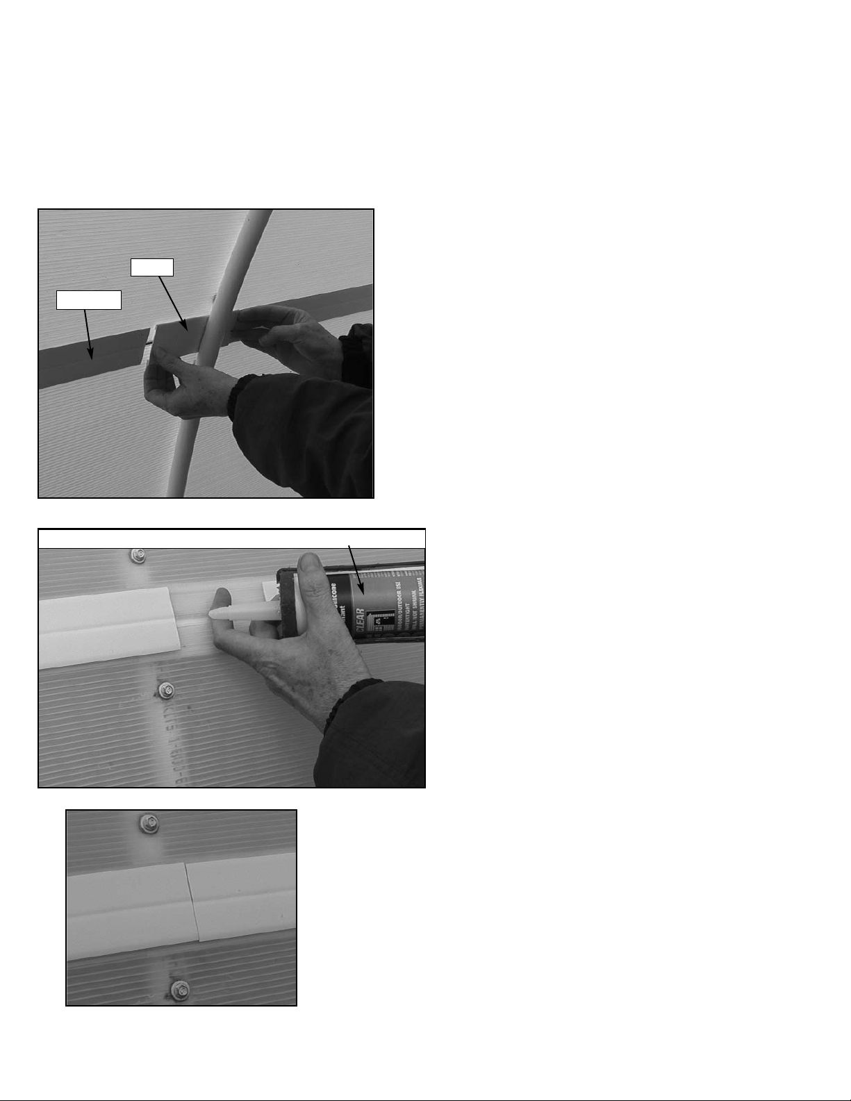
Installation instructions for
H-Channel Clips
1. Slide the H-Channel between the panels leaving a
couple inches between each piece of H-Channel.
From the inside of the greenhouse, slide the
H-Clip onto each end of the H-Channel pieces.
2. From the outside of the greenhouse,
insert about a nickel-size gob of 100%
silicone caulking into the area between
the H-Channel pieces.
3. Slide the H-Channel pieces in so they butt together.
IS 800 silicone rubber adhesive sealant or 100% silicone caulking
H-Clip
H-Channel

Page 20 12’ Garden Master (3.5mm)
uNOTE: Center the panels so the overhang is
equal over the front & back end
walls. Do not cut off the overhang.
It will help keep water out of the
end wall panels.
13B. TOP and SIDE GLAZING
Pieces Required:
2 49 ½” x 145” Panels
4 42” x 145” Panel
12 6’ H-Channel
6 H-Channel Clips
225 1” Screws
4 78” U-Trim
4 56” U-Trim
35 Small Phillips Screws
1. Caulk both ends of all six panels.
2. Lay a 49 ½” x 145” Panel on the ground and score (using a blunt object such as the back side of a butter knife) down the
center of the panel following a flute (Do not cut into the panel. You are only making a slight indenture in the panel, so when
you fold the panel, it follows this line.) Center the panel on the peak of the greenhouse, making sure there is equal
overhang over each end wall of the greenhouse. Attach with screws.
3. Attach a 42” x 145” panel ¼” below the top panel (the ¼” provides room for the H-Channel to be slide in). Score and fold
the panel down over the side ridge frame and down the side wall. - (Where the side of the greenhouse meets the roof.)
Repeat with a 42” x 145” Panel on the opposite side of the greenhouse.
4. Attach a 42” x 145” panel ¼” below the panel from step 3. Repeat with a 42” x 145” panel on the opposite side of the
greenhouse.
5. Cut a 49 ½” x 145” panel in half (to make two 24 ¾” x 145” panels) to fill in the the remaining spaces on each side of
the greenhouse. Remember to allow for ¼” between each of the panels for H-Channel.
6. Slide two 6’ H-Channels between each of the panels and join with H-Channel Clips (see instructions previous page).
7. Attach U-Trim to the panels (refer to hints on page 16). Cut U-Trim to fit when needed. Use two 56” and two 78” pieces on
each end of the greenhouse.
If you have purchased a tie down kit. Install it now!
If not, you will need to secure the greenhouse to the ground.
24 ¾” x 145” Panel
Score & fold 49 ½” x 145”
Panel at peak of greenhouse.
42” x 145” Panels
12’ H-Channel
Table of contents
Popular Greenhouse Kit manuals by other brands


Zip Tie Domes
Zip Tie Domes 2V Assembly manual

Vitavia
Vitavia Hera 4500 Assembly instructions

Robinsons
Robinsons Radley Series Assembly instructions

ModuLaro
ModuLaro GH192002 Assembly, installation and maintenance manual

juwel
juwel 20150 Mounting instructions

Vitavia
Vitavia Calypso 3000 Assembly instructions


