harvst S24 User manual
Setup guide
Model S24
Greenhouse only
V4/ From January 2023
If you have a Smart Sprout please also use the smart setup guide whilst
assembling your S24
1

Thank you for buying a Harvst Sprout mini
greenhouse.
You can also follow our step by step guide on youtube:
https://www.youtube.com/watch?v=jWL5YH0OSg4&list=PLKLY4TE98Co9
VRVXQ2BDlPrBSCeyHmhpR
If you have any questions while setting up, send us an email
(help@harvst.co.uk) or check out our forums:
https://grow.harvst.co.uk
SCAN ME WITH YOUR CAMERA:
Important information
Sprout Mini Greenhouses are intended for outdoor use and should be
secured to a fence or wall with the provided fixings. Harvst accept no
liability for incorrectly used products.
2
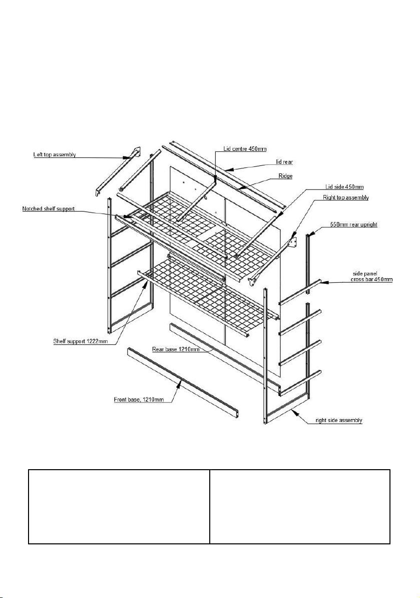
Exploded diagram
Tools provided
3mm allen key, 4mm allen key
8mm spanner
Pozidrive screwdriver
Tools required (not supplied)
Tape measure to identify parts
Secateurs for cutting pipe
3

Parts list (aluminium pieces)
450mm x3
2 lid sides with corner
1 lid centre
1210mm x1
Front crossbar
Double channel trim
attached
450mm x8
Side panel crossbar
2 pre-installed screws per piece
1210mm x1
Lid front bar
558mm x2
Rear upright (top pieces)
Lid prop x2
2 x side assemblies
Front uprights -1285mm
Rear uprights - 910mm
Base extrusion - 450mm
Shelf supports x4
1 pair notched - 1222mm
1 pair drilled - 1210mm
H trim
830mm x1
1208mm x1
540mm x1
1210mm x2
Front and rear base parts
Front: double channel up
Rear: single channel up
4

1250mm x1
Lid bar rear
1250mm x1
Lid ridge
With black PVC channel
Lid ridge and ridge rear assembly
14” x 22” mesh panels x4
Fixings and small parts
Additional fixings will be supplied if your greenhouse comes with a smart control system. See
the control system setup guide for details.
M5 square nut x36
M5 washer x2
M5 Nyloc nut x12
M5 x 30mm x2
M5 x 8 button x20
M5 x 10 button x14
M5 x 8 cap x8
Shelf bracket x4
5

Joining strap x2
Fixing bracket x2
Lier arm plate
Lier adapter plate
Cable tie x10 long
Hole punch
4.5 x 30mm
countersunk head
screws x2
Blanking plug x15
4mm tube for fixing
shelves
90mm x4, 160mm
x2
4.5 x 30mm dome
head screw x2
O-ring x2
Roll of foil tape
Panels
6
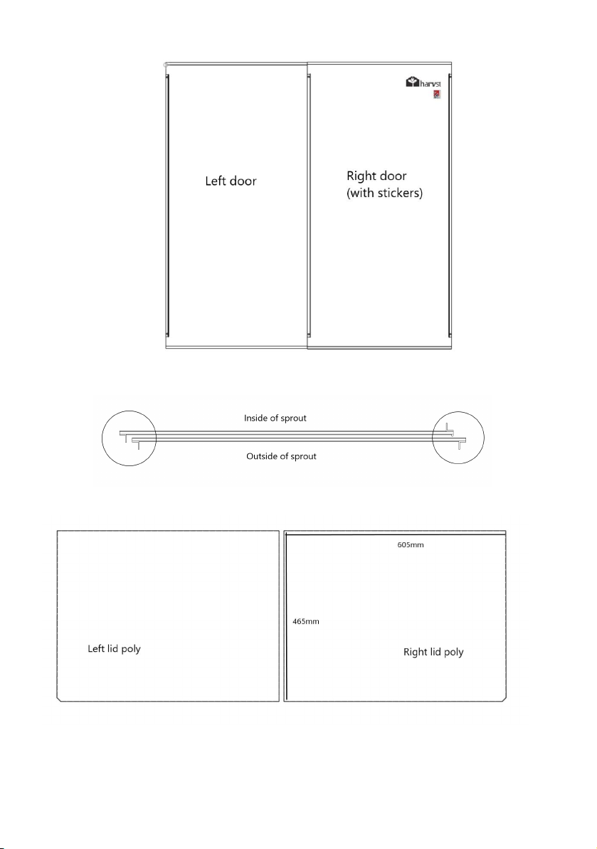
Top- looking down: Perspective of doors in sprout. Note the orientation of the handles
Above - note the orientation of the lid poly relative to the notches in the bottom le/right
respectively.
7

Poly side top panel - le x1
Note: Holes for piping
Poly side top panel - right x1
Poly side panels x8
8
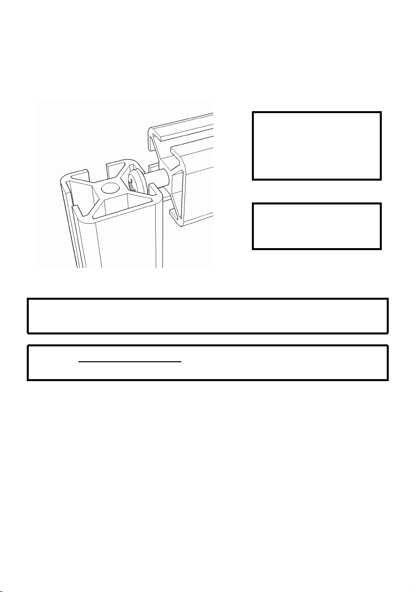
Slotting parts together
The greenhouse is based on parts that slot together using 30mm stainless steel screws, as shown
in the diagram below. These are self tapping screws which require a little bit of force to get them
fully seated.
Ensure that your screwdriver is
fully engaged with the screw
head when you tighten, so that
you donʼt round off the head of
the screw.
Note the orientation of each
piece in the description;
specifically the closed face.
WARNING Every care has been taken during manufacture to avoid sharp edges or burrs,
however you should still take care when handling metal parts.
WARNING DO NOT USE POWER TOOLS TO SCREW IN THE SCREWS. YOU MIGHT SNAP OFF
THE HEAD, WHICH IS NOT COVERED BY WARRANTY.
9

Step 1 - Seal the polycarbonate panels (optional)
This step is optional, but is recommended.
Twin wall polycarbonate panels act like double glazing for your mini greenhouse. To improve the
insulation characteristics, itʼs good to seal the ends of the channels using the foil tape provided.
It also helps prevent bugs from crawling into the plastic.
1. Peel back a couple of inches of the protective foil which covers both sides of the panels,
but donʼt take it all the way off yet.
2. Apply the tape to the end of the panel, covering the flutes / open ends.
3. Fold down the sides to seal the tape to the panels.
The white film is on the UV protected side which should face outwards when you place the
panels into the greenhouse.
Step 2 - Assembling the base
Parts:
1 x le assembly
1 x right assembly
1 x front base 121cm
1 x rear base 121cm
The le and right
assemblies are
interchangeable.
This step is best done
on a flat surface where
you can easily access
the screws at the
bottom, such as a
table or workbench.
NOTE:
The rear base part has
the single channel
facing up, and the
front has the double
channel facing up.
10
Other manuals for S24
2
Table of contents
Other harvst Greenhouse Kit manuals

harvst
harvst Sprout S6 Mini User manual

harvst
harvst Sprout S6 Mini User manual

harvst
harvst WaterMate User manual

harvst
harvst S14 User manual

harvst
harvst Sprout S10 Mini User manual

harvst
harvst Yard User manual

harvst
harvst S14 User manual

harvst
harvst Terrace User manual

harvst
harvst Harvster User manual

harvst
harvst S24 User manual


Popular Greenhouse Kit manuals by other brands

ACD PRESTIGE
ACD PRESTIGE MR3 H manual

Vitavia
Vitavia VA0040-TRP Assembly instructions

VegTrug
VegTrug Nursery manual

Riverstone Networks
Riverstone Networks Monticello 041315V Assembly instructions

STC
STC Easy Grow 6x12 Greenhouse Assembly instructions

CLIMA POD
CLIMA POD Spirit V7 Series Assembly instructions


