Solid Apollo Neon LED User manual

Page 1
Product Description
Main Functions:
USER MANUAL
Neon LED Conguration
Neon LED Conguration
Neon LED comes ready for customization to t almost any lighting project. This user guide is intended to instruct anyone on how to re-
power Neon LED, add joiners and an endcap.
This user manual can be used when extra Neon LED has been left over from an installation or if extra Neon LED needs to be added, or
during an installation where unexpected gaps or jumps are suddenly required. Basically every part of making a fully waterproof and
long lasting installation is covered in this user manual.
Power Adapter: For re-powering a piece of Neon LED
Joiner: Used for reconnecting Neon LED
Endcap: For adding a waterproof seal to the end of Neon LED
Mounting Bracket: For rmly attaching Neon LED
This manual reviews:
Toll Free: 866.592.3873
Email: [email protected]
www.SolidApollo.com
• Entire waterproof and conguration process
• How to add a power adapter
• How to install a joiner
• How to add the endcap
• How to install the mounting bracket
Neon LED
Technical Features:
OperatingVoltage: 120V AC
Watts Per Foot: 2.42W
Cut Points: Every 19.69 inches
36 LED’s per foot
USER MANUAL
Neon LED Conguration
Neon LED Conguration
Toll Free: 866.592.3873
Email: [email protected]om
www.SolidApollo.com
Installation
This section will show you how to cut the Neon LED, add a power adapter, install a joiner, and add an endcap to complete the conguration
for a fully waterproof seal.This manual also covers how to mount, install and use the mounting brackets. All Neon LED can only be pow-
ered in one direction. When cutting Neon, try to keep track of which end is cut. Please note, for outdoor or high humidity applications,
we recommend using waterproong glue for all connections (as noted in instructions), and we recommend at least 24 hours of drying time
before installing or using the Neon.
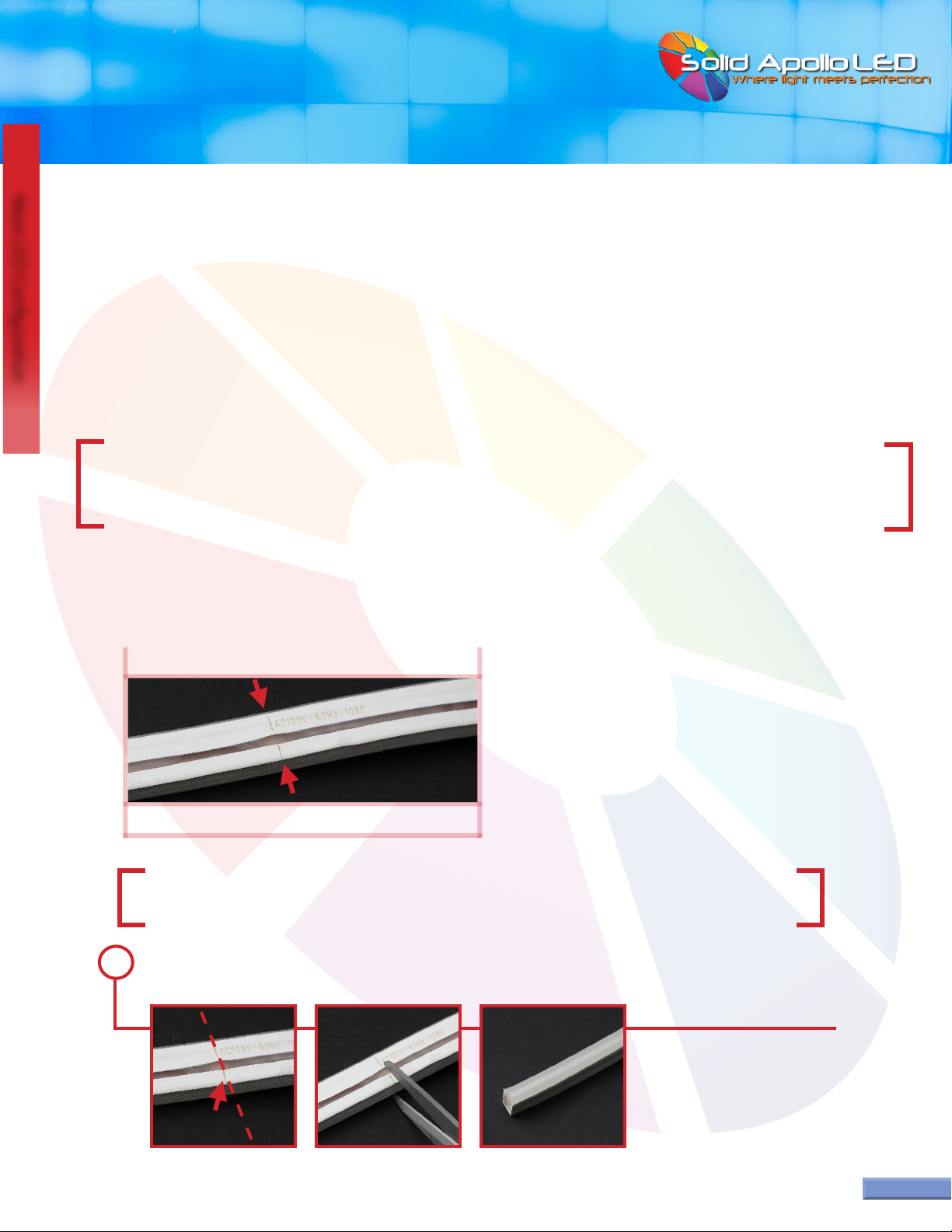
Cutting the Neon:
Warning: Neon LED must be unplugged when any modications are performed. 120V AC
Current is Dangerous and may cause electrical shock, injury and in some cases death.
Tools Required:
Sharp Metal Scissors or Shears (for cutting Neon at cut points)
Paper Towels (for excess glue)
Tong or Tweezer (for prong removal during testing)
Find the cut point on the Neon LED. Imagine a line passing from one side of the Neon LED to the other with the center being the
cut point symbol.Take either scissors or shears and line it up perpendicularly to the cut point and cut through the Neon LED.
Each Neon LED has cut points every 18”inches. Refer to the diagrams below for the cut point symbol found on the Neon LED.
Cut on line
Warning: Any tool with a blade is dangerous, and caution is advised when handling any blade. Please make sure
hands and ngers are kept at least several inches away from any blade and are not placed in the direction of the blade.
1
...continued on next page
Page 2
Neon LED Cut Point:
Neon LED (2-Prong)
CUT POINT
CUT POINT
USER MANUAL
Neon LED Conguration
Neon LED Conguration
Toll Free: 866.592.3873
Email: [email protected]om
www.SolidApollo.com
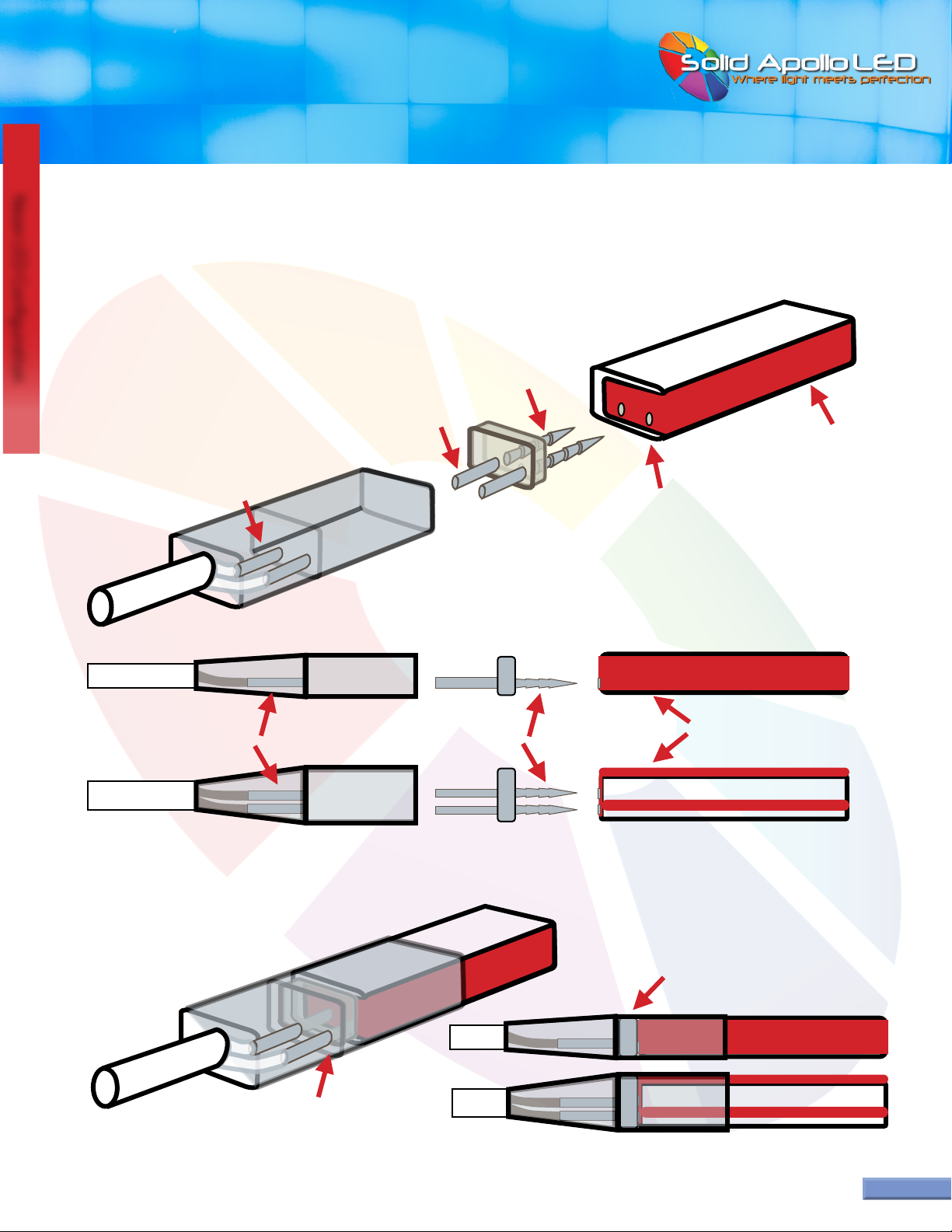
PRONG
prongs insert in
bottom wires
insert prong in
bottom wires
(can only be used
in one direction)
(can only be powered
in one direction)
prong barrels insert in
bottom wires on bottom
and to the right
plastic prong part slides
in to touch back wall
plastic prong part slides
in to touch back wall
pointy ends
Neon Color on Side
Neon Color on Side
barrel ends
prong barrels on bottom
and to the right NEON LED
CONNECTOR
Page 3
Connector Orientation:
CORRECT ORIENTATION:
FOR INSTALLATION
CORRECT ORIENTATION:
AFTER CONNECTION
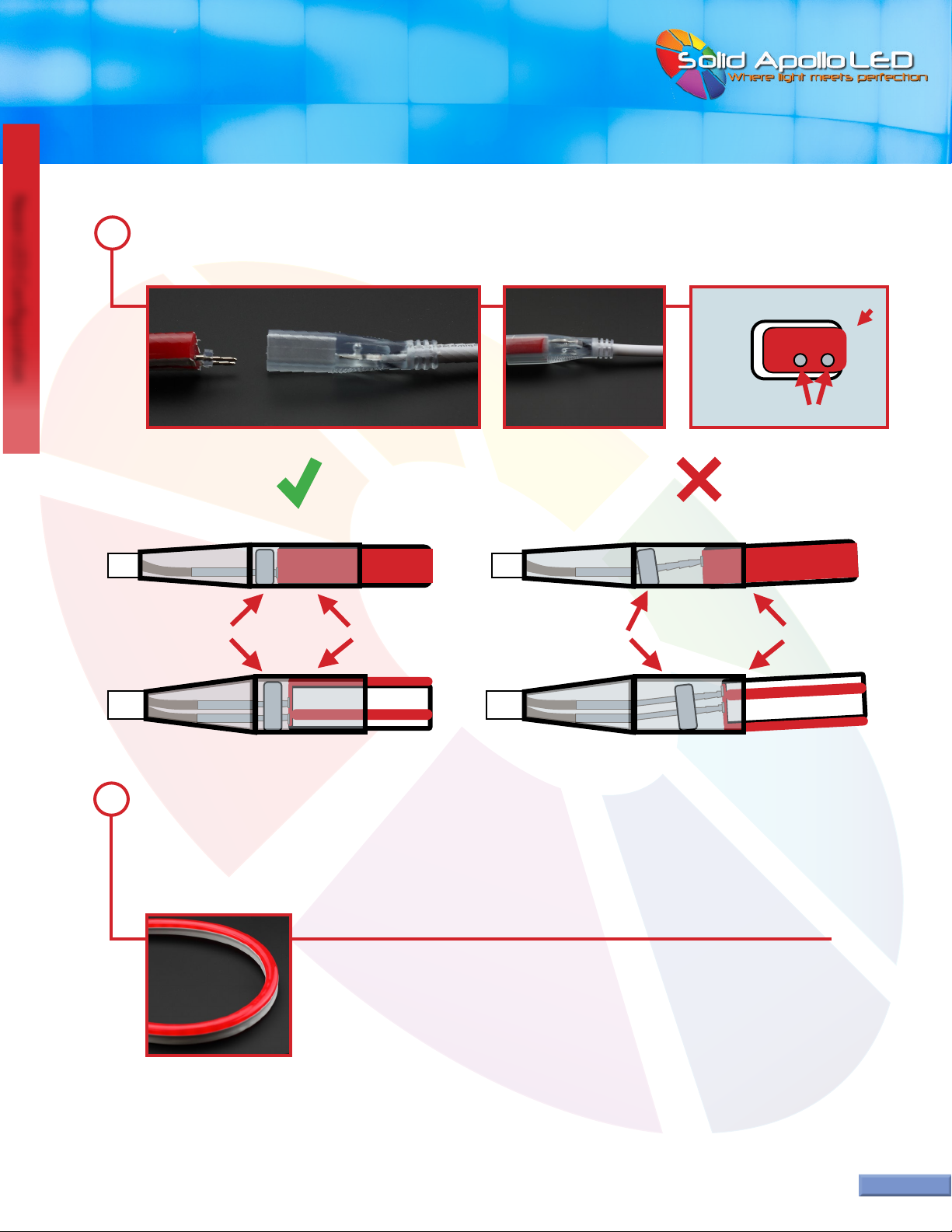
The orientation between the prongs and the connector must match for correct installation. The pointy end of the prong can only be
inserted into the Neon LED. The barrel end (non-pointy end) of the prong can only be inserted into the connector. The prongs and barrel
connectors must always be on the bottom and to the right to work correctly.
...continued on next page
USER MANUAL
Neon LED Conguration
Neon LED Conguration
Toll Free: 866.592.3873
Email: [email protected]om
www.SolidApollo.com
Page 4
Pictures of Correct Connector Orientation
Neon LED (2-Prong)
PRONG BARRELS ON BOTTOM PRONGS ON BOTTOM
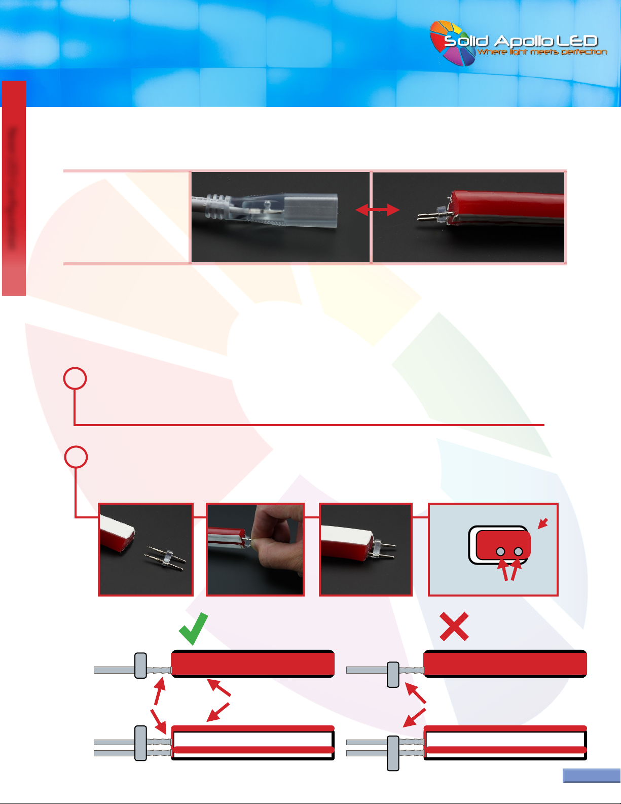
First, the components need to be tested to conrm they work before adding any glue. The Neon LED can only be powered
from one end. If you are unsure which end is correct, one end at a time must be tested to nd the correct end for adding
power for the Neon LED to work.
1
Powering the Neon:
In this section you will learn how to add the power adapter to any cut point on the Neon LED.
...continued on next page
For more information see Page 15 for detailed pictures of Neon LED and the matching parts
Take the prong and line it up to the Neon LED making sure the prong is oriented in the correct direction. Carefully insert
the pointy end of the prong into exposed wire ends.Try to have each prong insert into the center of each exposed wire
end.The prong needs to be inserted as far as possible without using excessive force.
2
insert prong in bottom right wires
Neon on Side
NEON
END
plastic bracket on prong does not
match shape of Neon
CORRECT: INCORRECT:
prongs insert in
bottom wires
Neon Color on Side
USER MANUAL
Neon LED Conguration
Neon LED Conguration
Toll Free: 866.592.3873
Email: [email protected]om
www.SolidApollo.com
Page 5
...continued on next page
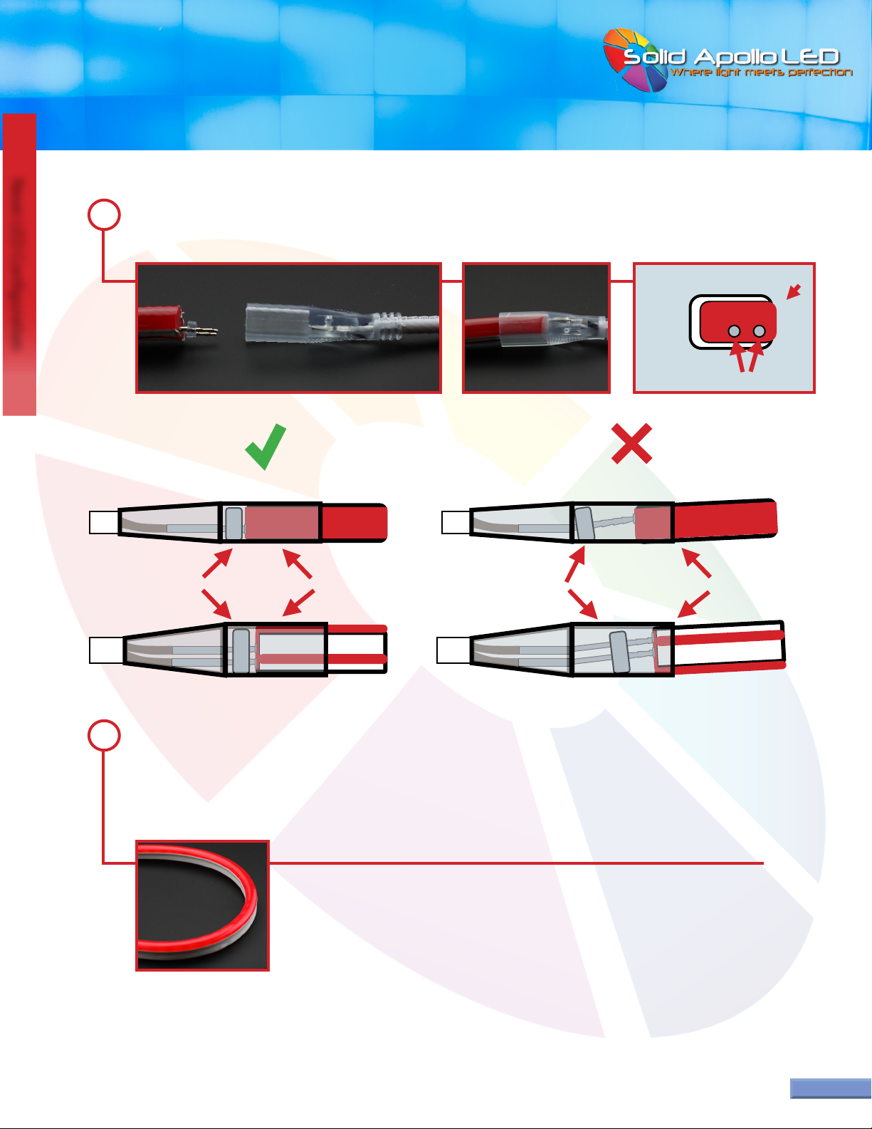
Then take the Neon LED with the prong and insert it into the power adapter connector in the correct orientation.The
prongs will slide into the small barrels inside the connector.
3
CORRECT: INCORRECT:
Take the plug on the power adapter and connect it into the wall outlet. Warning: The opposite end of the Neon LED
has not been sealed and must not touch any conductive material or electric shock or injury could occur.
If the lights turn on, then the prong was inserted into the correct end of the Neon. If the Neon LED does not come on,
then unplug the power adapter and repeat from step 1 to test the opposite end of the Neon. Tweezers or tongs maybe
required to remove the prongs if they are stuck inside the connector.
4
insert prong in bottom right wires
Neon on Side
NEON
END
plastic bracket
ts in straight plastic bracket
crooked
Neon ts in straight Neon is not straight

USER MANUAL
Neon LED Conguration
Neon LED Conguration
After conrming the Neon LED works, unplug the Neon LED from the wall outlet. Carefully pull the power adapter
o the Neon. The prongs are sometimes stuck inside the connector on the power adapter and require a set of tweezers or
tongs to pull the prong out.
5
Page 6
Toll Free: 866.592.3873
Email: [email protected]
www.SolidApollo.com
...continued on next page
The test phase is now complete, and the Neon LED, prong and connector can be assembled for the last time.Take the
prongs and reinsert them into the Neon in the correct orientation.The prong needs to be inserted as far as possible
without using excessive force. Then take the connector end of the power adapter and ll it half way with silicone glue.
6
Take the Neon LED with the prong and re-insert it into the connector of the power adapter, making sure it is inserted in
the correct orientation. Push the Neon and the connector together, until the plastic bracket on the prong touches the
inner wall of the connector on the power adapter.
7
PLASTIC BRACKET HALFWAY IN PLASTIC BRACKET FULLY IN
USER MANUAL
Neon LED Conguration
Neon LED Conguration
Page 7
Toll Free: 866.592.3873
Email: [email protected]
www.SolidApollo.com
Extra glue usually comes out at the connection. Take your nger and wipe the excess glue all the way around the connec-
tion point.Wipe extra glue onto the paper towel. Please note the conguration is not complete until an endcap is added
to the opposite end. If a joiner is not required, skip the next section and go to page 12 for adding the endcap.
8
When conguration is complete, we recommend at least 24 hours of drying time before installing or using the
Neon LED. Be careful when handling the Neon while it is drying, as connections could come apart. We recom-
mend taping the connections if the neon needs to be handled multiple times during conguration.

USER MANUAL
Neon LED Conguration
Neon LED Conguration
™
Toll Free: 866.592.3873
Email: [email protected]
www.SolidApollo.com
Page 8
First, the components need to be tested to conrm they work before adding any glue. The Neon LED can only be powered
from one end. If the extra piece of Neon LED needs to be cut follow the rest of this step, otherwise skip to step 2. Find the
cut point you want to add an interconnector to. Cut at the cut point as noted on page 2 titled“Cutting the Neon.”
1
Installing a Joiner:
In this section you will add a joiner to any cut point on the Neon LED.
Joiner: Used for attaching extra Neon LED where no gaps
are needed
CUT POINT
...continued on next page
Take the prong and line it up to the Neon LED making sure the prong is oriented in the correct direction. Carefully insert
the pointy end of the prong into exposed wire ends.Try to have each prong insert into the center of each exposed wire
end.The prong needs to be inserted as far as possible without using excessive force.
2
insert prong in bottom right wires
Neon on Side
NEON
END
plastic bracket on prong does not
match shape of Neon
CORRECT: INCORRECT:
prongs insert in
bottom wires
Neon Color on Side
USER MANUAL
Neon LED Conguration
Neon LED Conguration
Page 9
Toll Free: 866.592.3873
Email: [email protected]
www.SolidApollo.com
...continued on next page
Then take the Neon LED with the prong and insert it into the power adapter connector in the correct orientation.The
prongs will slide into the small barrels inside the connector.
3
insert prong in bottom right wires
Neon on Side
NEON
END
CORRECT: INCORRECT:
plastic bracket
ts in straight plastic bracket
crooked
Neon ts in straight Neon is not straight
Take the plug on the power adapter and connect it into the wall outlet. Warning: The opposite end of the Neon LED
has not been sealed and must not touch any conductive material or electric shock or injury could occur. If
the Neon LED turns on, then the prong was inserted into the correct end of the Neon. If the Neon LED does not come on,
then unplug the power adapter and repeat from step 1 to test the opposite end of the Neon. Tweezers or tongs maybe
required to remove the prongs if they are stuck inside the connector.
4

USER MANUAL
Neon LED Conguration
Neon LED Conguration
Page 10
Toll Free: 866.592.3873
Email: [email protected]
www.SolidApollo.com
After conrming the lights work, unplug the Neon LED from the wall outlet. Carefully pull the power adapter o
the Neon. The prongs are sometimes stuck inside the connector on the power adapter and require a set of tweezers or
tongs to pull the prong out.
5
...continued on next page
The test phase is now complete, and the Neon LED, prong and connector can be assembled for the last time.Take the
prongs and reinsert them into the Neon in the correct orientation.The prong needs to be inserted as far as possible
without using excessive force. Then take the connector end of the power adapter and ll it half way with silicone glue.
6
Take the Neon LED with the prong and re-insert it into the connector of the power adapter, making sure it is inserted in
the correct orientation. Push the Neon and the connector together, until the plastic bracket on the prong touches the
inner wall of the connector on the power adapter.
7
PLASTIC BRACKET HALFWAY IN PLASTIC BRACKET FULLY IN

USER MANUAL
Neon LED Conguration
Neon LED Conguration
™
Toll Free: 866.592.3873
Email: [email protected]
www.SolidApollo.com
Page 11
Extra glue usually comes out at the connection. Take your nger and wipe the excess glue all the way around the con-
nection point. Wipe extra glue onto the paper towel. Repeat the connection on the other side of the joiner by following
steps 5 through 7. Please note the conguration is not complete until an endcap is added to the opposite end (page 12).
8
When conguration is complete, we recommend at least 24 hours of drying time before installing or using the
Neon. Be careful when handling the neon while it is drying, as connections could come apart. We recommend
taping the connections if the neon needs to be handled multiple times during conguration.
USER MANUAL
Neon LED Conguration
Neon LED Conguration
™
Toll Free: 866.592.3873
Email: [email protected]
www.SolidApollo.com
Page 12
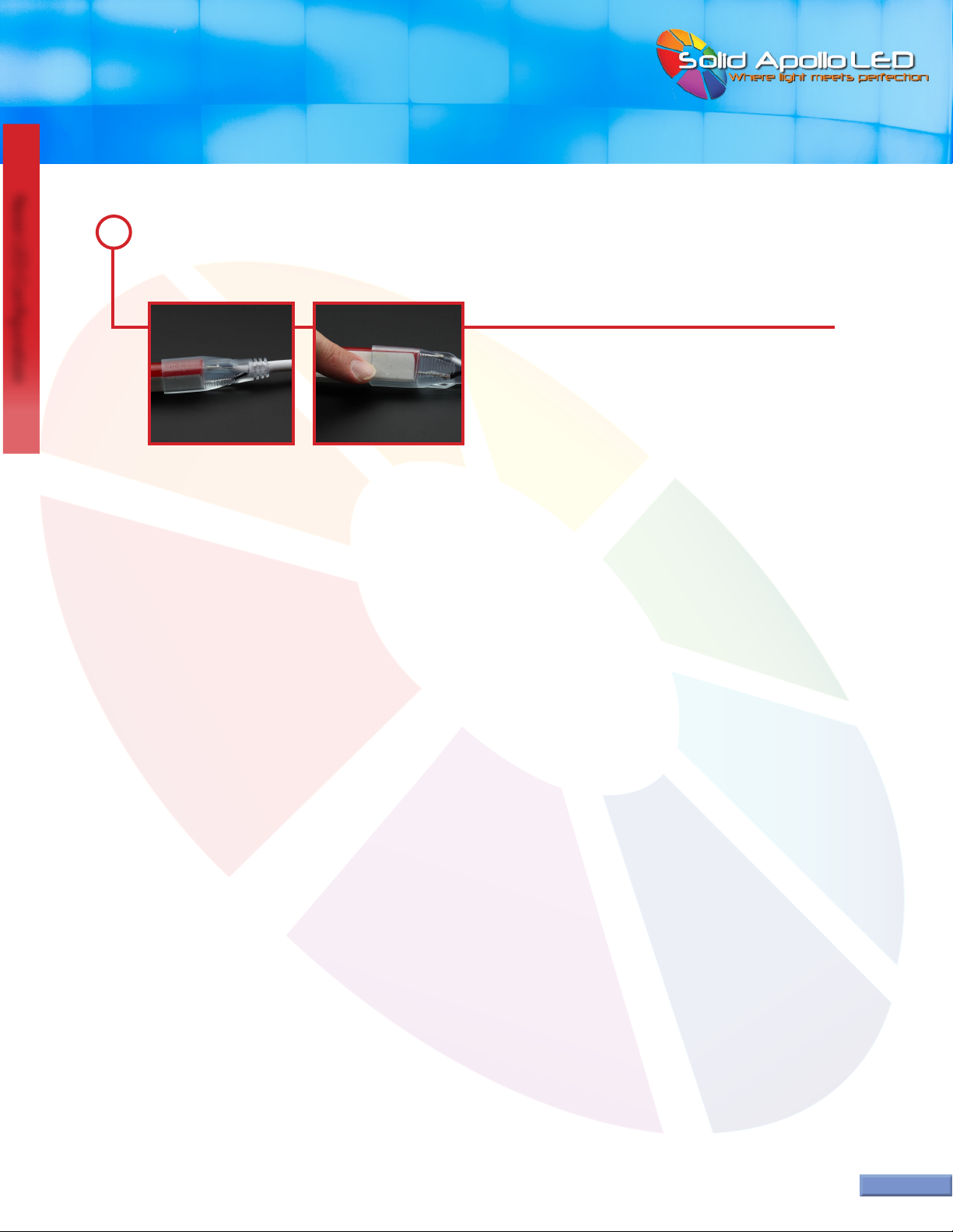
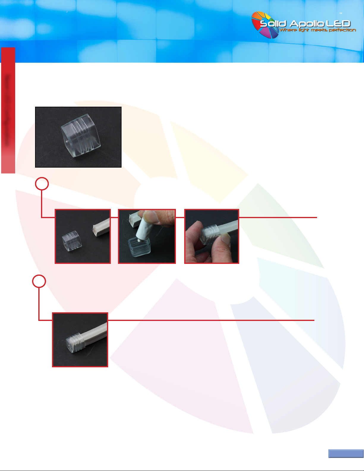
Take the endcap and ll it half way with silicone glue. Insert the endcap on the end of the Neon LED until the inner back
wall of the endcap is touching the end of the Neon. Sometimes the endcap has to be wiggled from side to side so the
back wall of the endcap touches the end of the Neon LED.
1
Adding an Endcap:
In this section you will learn how to add an end cap to seal the end of the Neon LED.
For drying, we recommend at least 24 hours of drying time before installing or using the Neon LED.
Extra glue usually comes out at the connection. Take your nger and wipe the excess glue all the way around the connec-
tion point.Wipe extra glue onto the paper towel.
2

USER MANUAL
Neon LED Conguration
Neon LED Conguration
™
Toll Free: 866.592.3873
Email: [email protected]
www.SolidApollo.com
Page 13
Plan the location where the mounting brackets will be placed.Take the mounting bracket and hold it up to the location
being mounted to.
1
Installing Mounting Brackets:
In this section you will learn how to mount the brackets for Neon LED. Each bracket includes 2 screws. Please note other types of screws
and hardware maybe required depending on the surface being mounted to. Please ask your local hardware store for advice if you are
unsure.
For straight lines, we suggest using a mounting bracket every foot for linear applications. If doing a large curve, make sure the Neon LED
will not be bent in 90 degree bends.We recommend attaching the brackets to test how many will be needed to hold the desired curve,
as several brackets could be required every foot.
With your other hand take a pencil or marker and mark the screw locations.
2
Tools Required:
Pencil
Phillips Head Screwdriver
Drill
Drill Bit
...continued on next page
USER MANUAL
Neon LED Conguration
Neon LED Conguration
™
Toll Free: 866.592.3873
Email: [email protected]
www.SolidApollo.com
Page 14
If you have any further questions, please contact us by phone or email using the contact information at
the top right of this page.
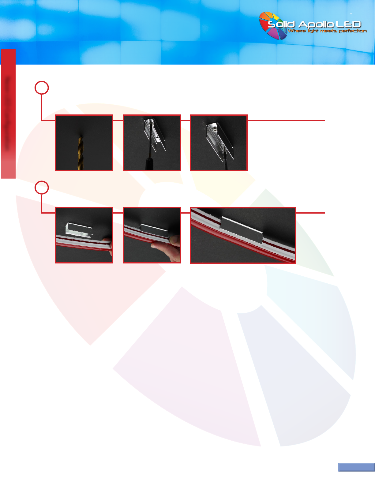
Remove the bracket, and drill pilot holes for the screws.Take a screw and the mounting bracket and begin inserting the
rst screw. Take the second screw and begin inserting the screw.Take a Phillips head screwdriver and screw in the rst
screw until it sits ush with the bottom of the bracket. Screw in the second screw until it is also ush.
Carefully press the Neon LED into the mounting bracket. Make sure the Neon is pressed in until it is touching the bottom
of the inside of the bracket.
3
4
Technical Specications:
Lumen’s Total: Up To 29700 Lm (Pure White Color)
Lumen’s Per Foot: Up to 180 Lm (PureWhite Color)
Total LED’s: 5220
LED’s Per Foot: 36
Operating Voltage: 120V AC
Watts Per Foot: 2.42W
Watts Per Spool: 400W
Dimmable: Yes
CRI: 82
LED Type: SMD 3528
Beam Angle : 180
USER MANUAL
Neon LED Conguration
Neon LED Conguration
Page 15
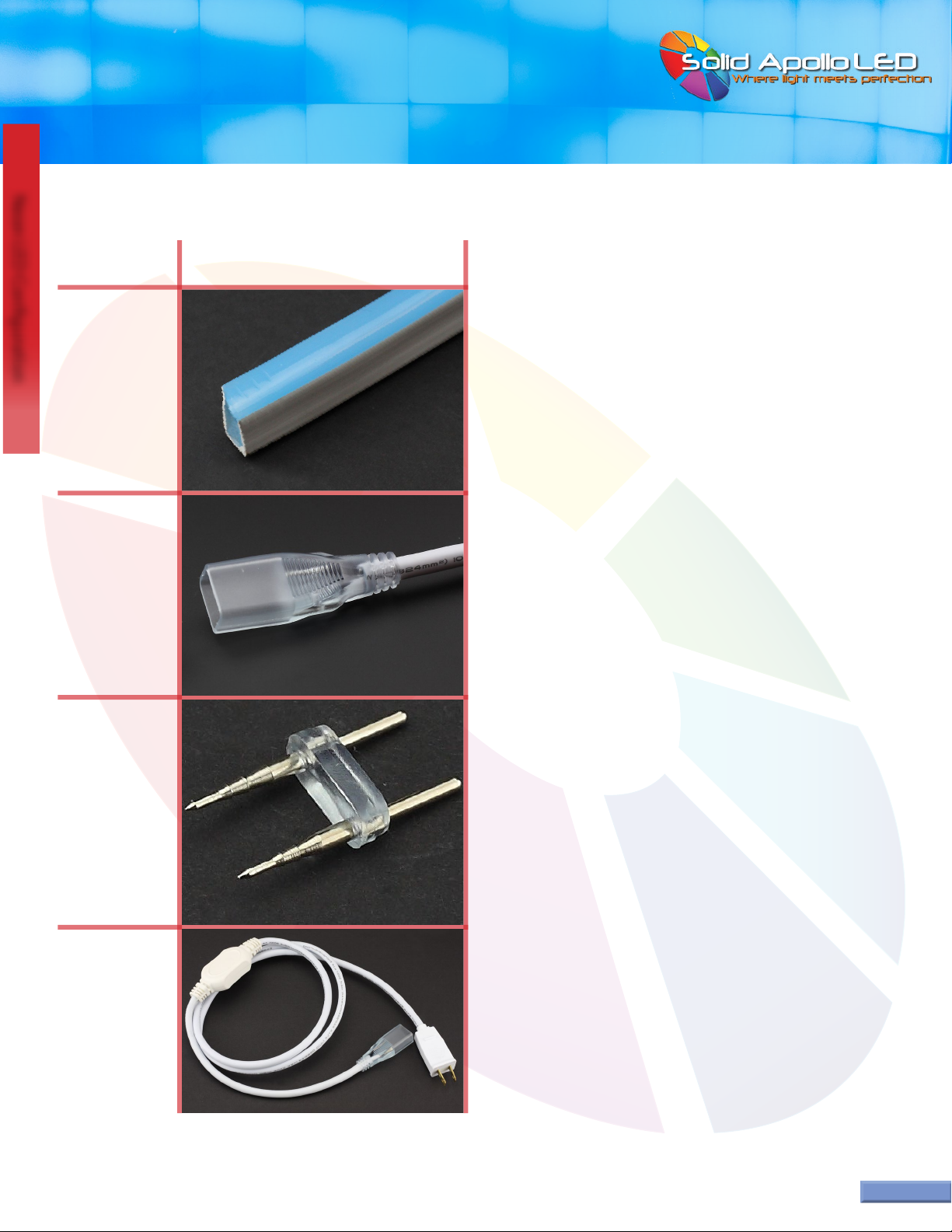
Neon LED and Matching Parts:
Toll Free: 866.592.3873
Email: [email protected]
www.SolidApollo.com
Neon LED
Prong
Connector
Power
Adapter
Neon LED (2-Prong)
Table of contents
Other Solid Apollo Lighting Equipment manuals


Popular Lighting Equipment manuals by other brands

Glow Bricks
Glow Bricks HarryPotter Hogwarts Express Collector's Edition Lego... installation guide

Atlas Copco
Atlas Copco QLT H40 instruction manual

LANZINI
LANZINI Pitagora manual

SGM
SGM PALCO 3 user manual

Newfeel
Newfeel F4 Series user manual

Vision & Control
Vision & Control LDLF30x360-B470/24V/-a Instructions for use

LumaPro
LumaPro 30UH85 operating instructions

American DJ
American DJ Mystic User instructions

walimex
walimex 16638 instruction manual

Commercial Electric
Commercial Electric 56574141 Use and care guide

Sony
Sony Halogen Lamp operating instructions

LED Group
LED Group ROBUS VEGAS RVA12RGBW6710-30 quick start guide


