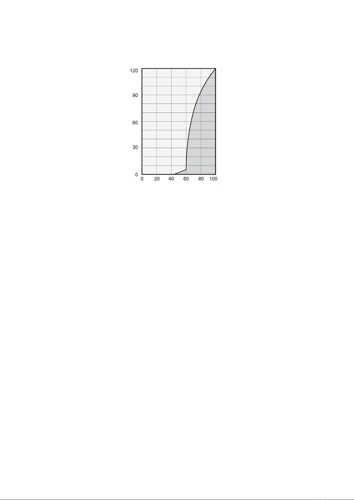
It is evident that the corrosion
rate below 50 % relative
humidity (RH) is low,
and below 40 % is negligible.
The corrosion rate increases
significantly above 60 % RH.
This threshold for damage
as the result of humidity also
applies to other materials, such
as powdery substances, packaging,
wood and electronic units.
Buildings may be dried in a variety
of ways:
1. By heating and air exchange:
The air in the room is heated
in order for moisture to
be removed and then this air
is fed outside. All of the energy
that is involved is lost together
with the moist air that is
released.
2. By air dehumidification:
The moist air that is present
within an enclosed space
is continuously dehumidified
according to the condensation
principle.
The correlations occurring when
air is dehumidified are based
on physical laws.
These are depicted here
in graphical form in order
to provide you with a brief
overview of the principles of air
dehumidification.
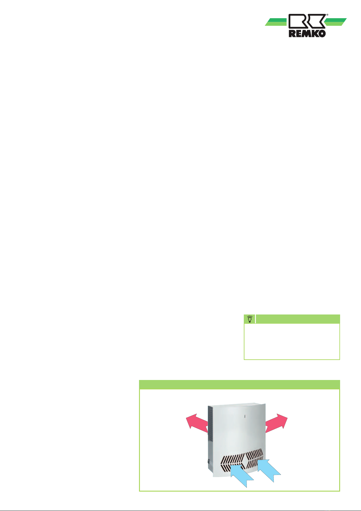
The use of
REMKO air dehumidifiers
– Even if windows and doors
are well insulated, water and
moisture are still capable of
penetrating thick concrete walls.
– The water required for setting
in the production of concrete,
mortar and plaster etc. may only
be diffused after 1-2 months.
– Even moisture trapped
in the masonry after high-
water or a flood is released very
slowly.
– The same is also true
of moisture contained in stored
materials for example.
The moisture (water vapour)
released from parts of a building
or materials is absorbed by
the surrounding air. As a result,
the moisture content increases,
which ultimately gives rise
to corrosion, mould, rot, peeling
of paint and other unwanted
damage.
By way of example, the diagram
shows the corrosion rate of metal
in different levels of humidity.
Air dehumidification
With regard to energy
consumption, air dehumidification
has one distinct advantage:
Energy expenditure is limited
exclusively to the air volumes
present. The mechanical heat that
is released by the dehumidification
process is fed back into the room.
Under normal use,
the
air dehumidifier
uses
approximately 25 %
of the energy that is required
for the
“heating and ventilating”
principle.
Relative air humidity
Our ambient air is a gaseous
mixture which always contains
a certain volume of water
in the form of water vapour.
This volume of water is specified
in g per kg of dry air (absolute
moisture content).
1 m3of air weighs approx. 1.2 kg
at 20 °C
Depending on the temperature,
each kg of air is only capable
of absorbing a certain volume
of water vapour. Once
this capacity has been reached,
the air is referred to as “saturated”
and has a relative humidity (RH)
of 100 %.
Relative humidity is understood
to mean the ratio between
the current quantity of water
vapour in the air and the maximum
possible quantity of water vapour
at the same temperature.
The ability of the air to absorb
water vapour increases
as the temperature rises. I.e.
the maximum possible (absolute)
water content becomes greater
as the temperature rises.
Corrosion speed
Relative humidity %
4
REMKO SLE series