Metalumen RAIL 4 User manual
570 Southgate Drive, Guelph, Ontario N1G 4P6
Mailing Address: P.O. Box 1779
Guelph, Ontario N1H 6Z9
T 1.800.621.6785 | T 519.822.4381 | F 519.822.4589
www.metalumen.com IS-0260-01 rev.00
PAGE 1 OF 6
Specications and design subject to change without notice.
NOTE: The following instructions provide general guidelines for product installation. For additional
information consult the applicable electrical codes or contact factory directly for support
before attempting anything with uncertainty.
CAUTION: Do not assemble xture runs on oor.
WARNING: Risk of re and electrical shock. DISCONNECT POWER AT ELECTRICAL PANEL before
installing or servicing this product.
GENERAL SAFETY INSTRUCTIONS:
1. Read all instructions prior to installing this xture.
2. This product must be installed in accordance with the applicable installation code by a person familiar
with the construction and operation of the product and the hazards involved.
3. All wiring must be performed by a qualied electrician in accordance with national and local building
and electrical codes.
4. This xture must be suitably grounded for your protection against shock hazards and to assure proper
operation.
5. Make sure that the power source conforms to the requirements of this xture.
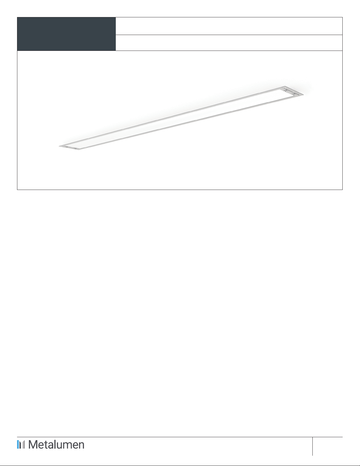
INSTALLATION
INSTRUCTIONS
RAIL 4
RM4DOD Recessed
Specications and design subject to change without notice.
570 Southgate Drive, Guelph, Ontario N1G 4P6
Mailing Address: P.O. Box 1779
Guelph, Ontario N1H 6Z9
T 1.800.621.6785 | T 519.822.4381 | F 519.822.4589
www.metalumen.com IS-0260-01 rev.00
PAGE 2 OF 6
INSTALLATION INSTRUCTIONS RM4DOD Recessed RAIL 4
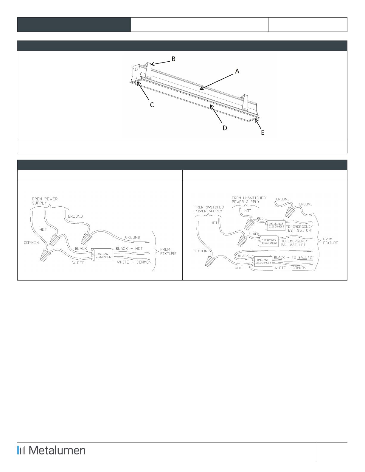
PARTS LIST
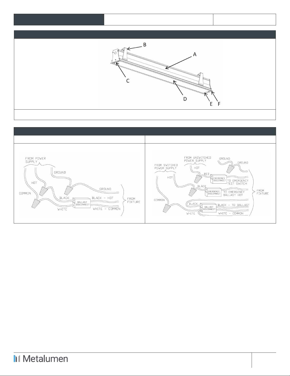
MAIN PARTS LIST
A. Luminaire Enclosure
B. Mounting Bracket
C. End Plate
D. Lens
E. End Screw
OTHER PARTS
• Reector
• Lamp (supplied or by others)
Important note: See xture size and recommended ceiling/canopy opening diagram at page 6 of this document.
WIRING DIAGRAMS
STANDARD WIRING WITH OPTIONAL EMERGENCY PACK
Specications and design subject to change without notice.
570 Southgate Drive, Guelph, Ontario N1G 4P6
Mailing Address: P.O. Box 1779
Guelph, Ontario N1H 6Z9
T 1.800.621.6785 | T 519.822.4381 | F 519.822.4589
www.metalumen.com IS-0260-01 rev.00
PAGE 3 OF 6
INSTALLATION INSTRUCTIONS RM4DOD Recessed RAIL 4
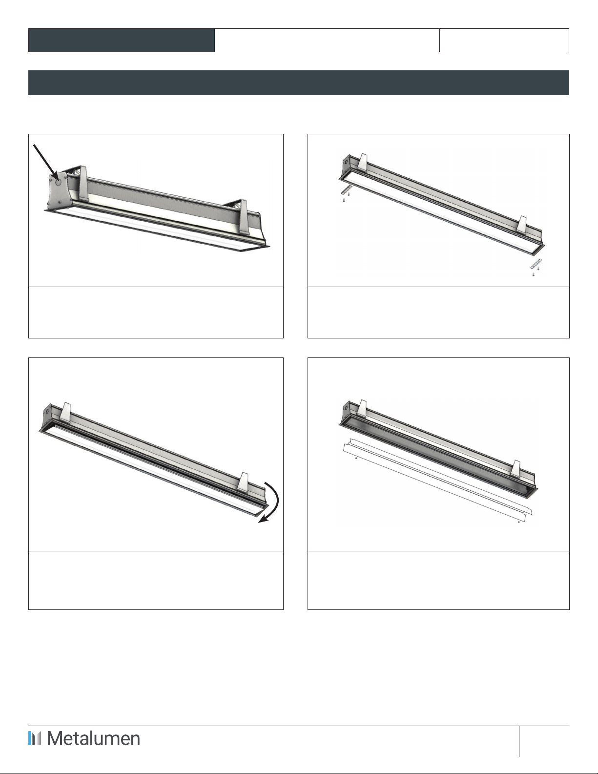
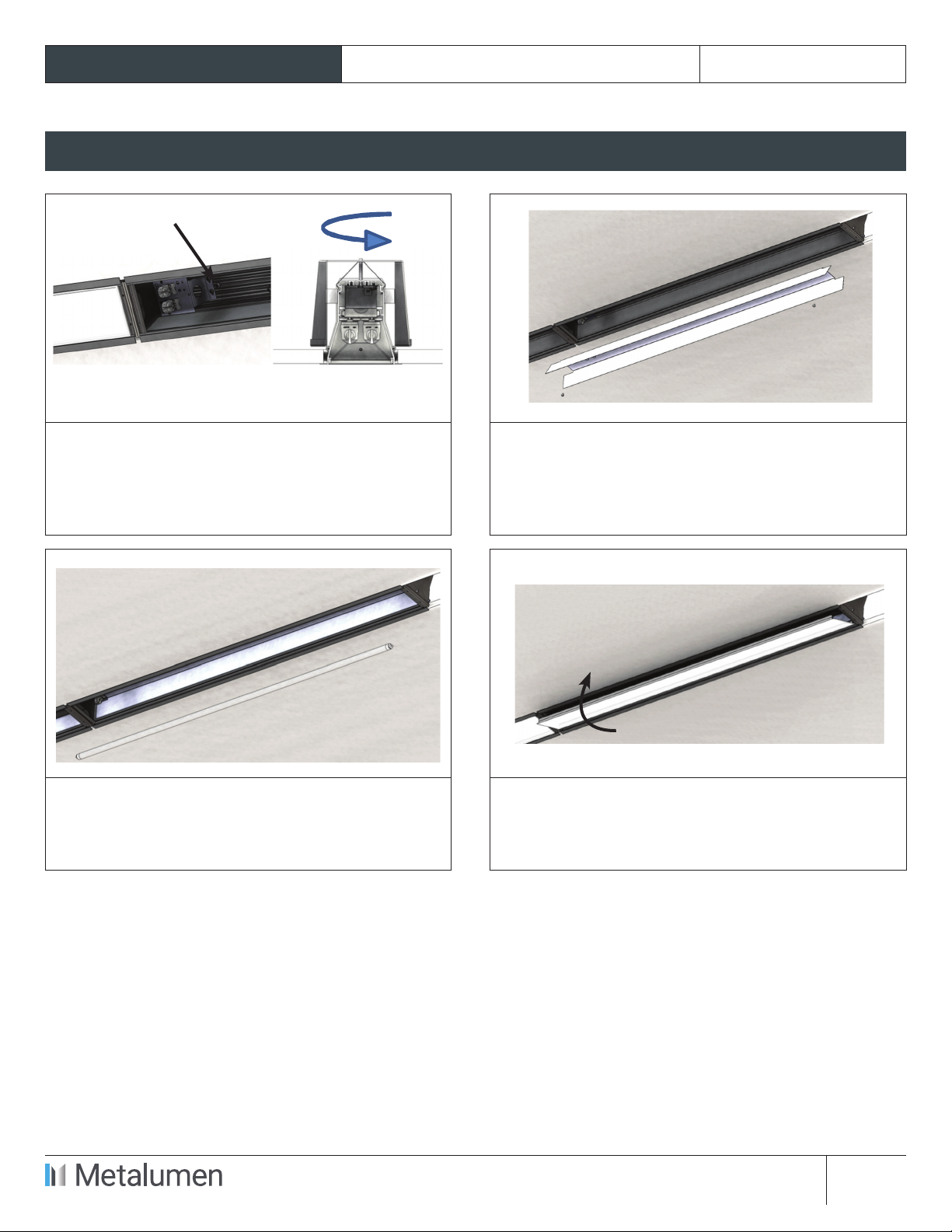
STEP-BY-STEP INSTRUCTIONS
STEP 1. Remove xture packaging; note marked
supply wires coming out at one end of the
luminaire.
STEP 2. Remove end screws (E) and end plates (C).
Keep all parts.
STEP 3. Remove lens (D) starting at one end. Pull
one side rst, rotate and detach. Keep lens.
STEP 4. Remove reector mounting screws and
reector. Note xtures with optional emergency
pack have a test switch and indicator light
mounted on the reector.
Specications and design subject to change without notice.
570 Southgate Drive, Guelph, Ontario N1G 4P6
Mailing Address: P.O. Box 1779
Guelph, Ontario N1H 6Z9
T 1.800.621.6785 | T 519.822.4381 | F 519.822.4589
www.metalumen.com IS-0260-01 rev.00
PAGE 4 OF 6
INSTALLATION INSTRUCTIONS RM4DOD Recessed RAIL 4
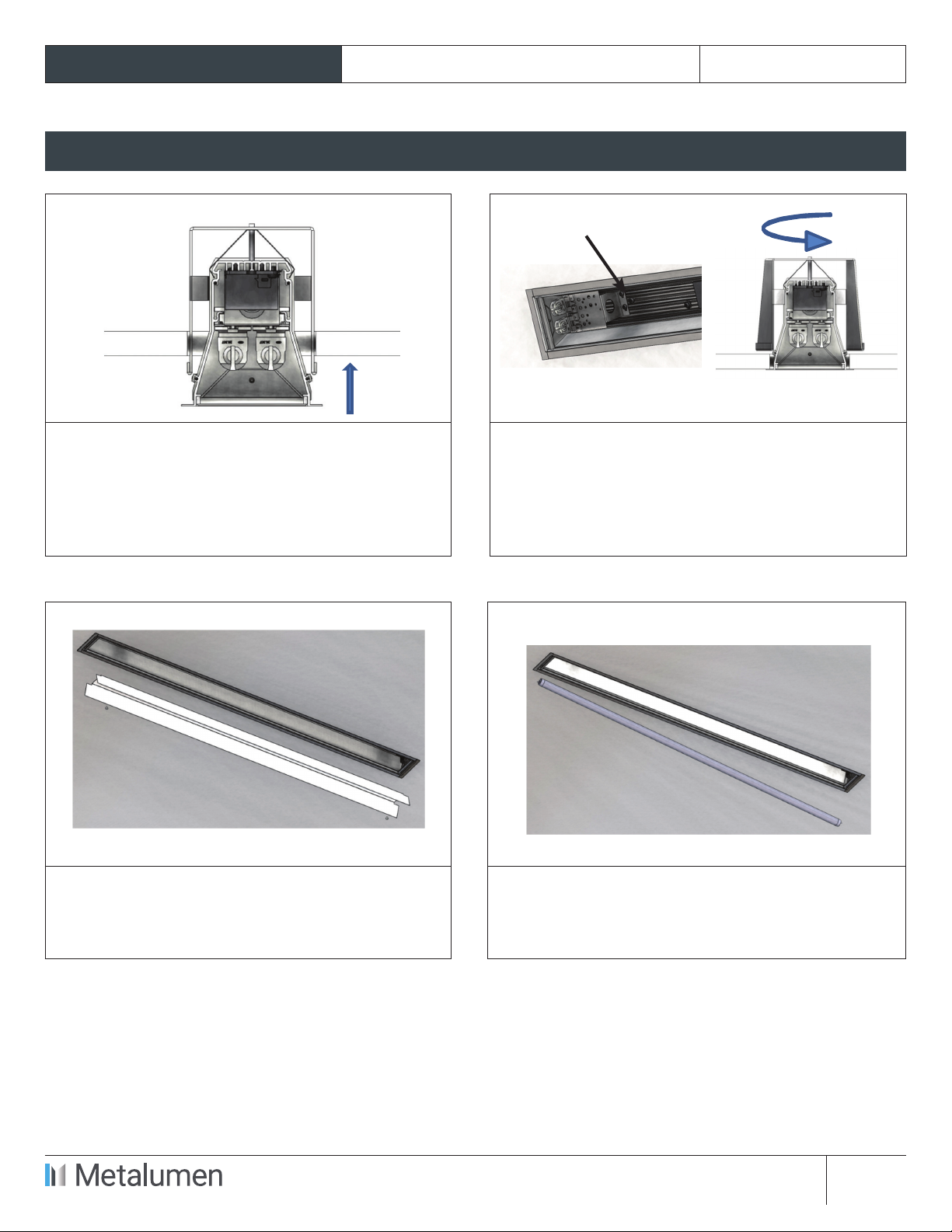
STEP-BY-STEP INSTRUCTIONS
STEP 5. Bring electrical supply to the xture as
needed. Make sure all mounting brackets (B) are
parallel to the luminaire enclosure (A) and insert
xture all the way through the opening in the
ceiling.
STEP 6. Identify mounting screws (start at one
end of the xture). Begin tightening the mounting
screws. Mounting brackets will swing out and
retain the luminaire in place. Continue to tighten
the screws until the luminaire anges are ush
with the ceiling.
STEP 7. Perform electrical wiring inside the
xture and re-attach reector with (2) mounting
screws. Optional emergency ballast must be fed
from the same branch circuit as the AC ballast.
STEP 8. Install lamp(s).
Specications and design subject to change without notice.
570 Southgate Drive, Guelph, Ontario N1G 4P6
Mailing Address: P.O. Box 1779
Guelph, Ontario N1H 6Z9
T 1.800.621.6785 | T 519.822.4381 | F 519.822.4589
www.metalumen.com IS-0260-01 rev.00
PAGE 5 OF 6
INSTALLATION INSTRUCTIONS RM4DOD Recessed RAIL 4
STEP-BY-STEP INSTRUCTIONS
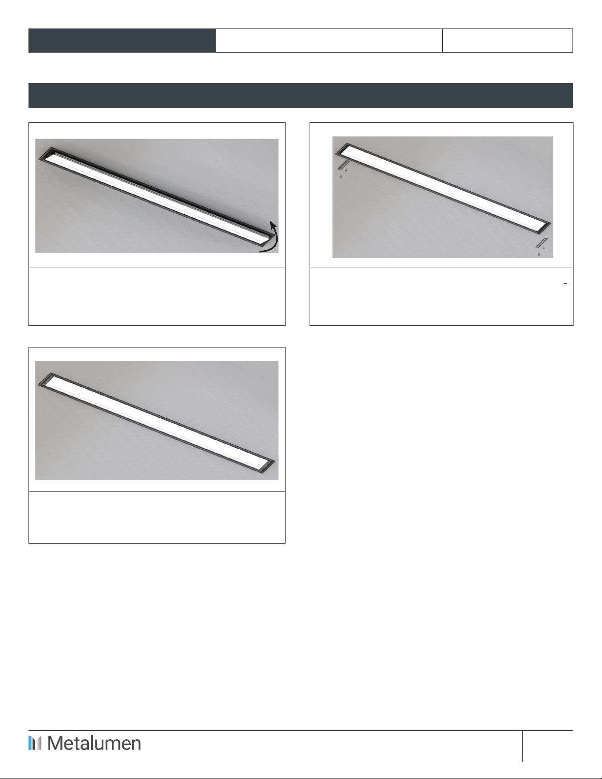
STEP 9. Re-attach lens. Start with one side
rst and close the other side starting from the
corner. Make sure lens gaskets are in place and
compressed between lens and xture housing.
STEP 10. Re-attach end plates with (4) end screws.
STEP 11. Installed xture.

Specications and design subject to change without notice.
570 Southgate Drive, Guelph, Ontario N1G 4P6
Mailing Address: P.O. Box 1779
Guelph, Ontario N1H 6Z9
T 1.800.621.6785 | T 519.822.4381 | F 519.822.4589
www.metalumen.com IS-0260-01 rev.00
PAGE 6 OF 6
INSTALLATION INSTRUCTIONS RM4DOD Recessed RAIL 4
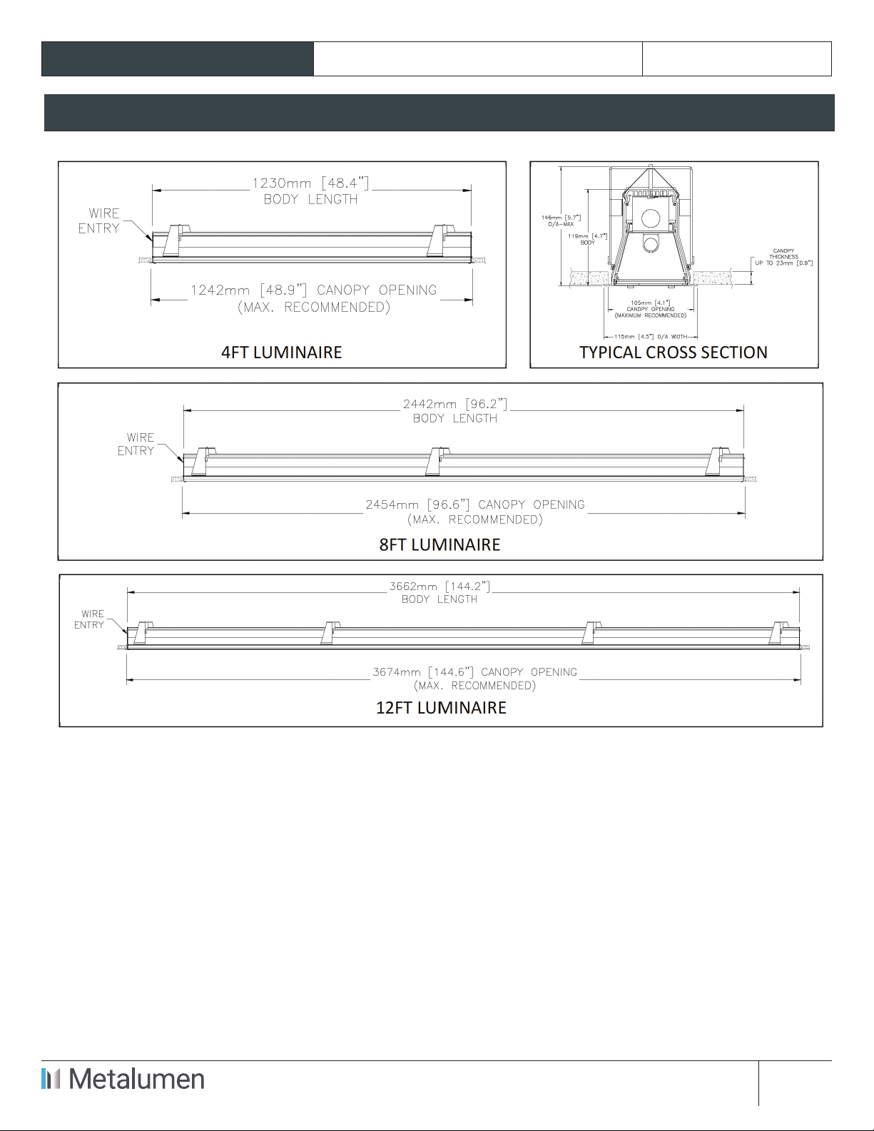
Fixture size and recommended ceiling/canopy opening Diagram:

Specications and design subject to change without notice.
570 Southgate Drive, Guelph, Ontario N1G 4P6
Mailing Address: P.O. Box 1779
Guelph, Ontario N1H 6Z9
T 1.800.621.6785 | T 519.822.4381 | F 519.822.4589
www.metalumen.com IS-0260-02 rev.00
PAGE 1 OF 7
NOTE: The following instructions provide general guidelines for product installation. For additional
information consult the applicable electrical codes or contact factory directly for support
before attempting anything with uncertainty.
CAUTION: Do not assemble xture runs on oor.
WARNING: Risk of re and electrical shock. DISCONNECT POWER AT ELECTRICAL PANEL before
installing or servicing this product.
GENERAL SAFETY INSTRUCTIONS:
1. Read all instructions prior to installing this xture.
2. This product must be installed in accordance with the applicable installation code by a person familiar
with the construction and operation of the product and the hazards involved.
3. All wiring must be performed by a qualied electrician in accordance with national and local building
and electrical codes.
4. This xture must be suitably grounded for your protection against shock hazards and to assure proper
operation.
5. Make sure that the power source conforms to the requirements of this xture.
JOINING
INSTRUCTIONS
RAIL 4
RM4DOD Recessed
Specications and design subject to change without notice.
570 Southgate Drive, Guelph, Ontario N1G 4P6
Mailing Address: P.O. Box 1779
Guelph, Ontario N1H 6Z9
T 1.800.621.6785 | T 519.822.4381 | F 519.822.4589
www.metalumen.com IS-0260-02 rev.00
PAGE 2 OF 7
JOINING INSTRUCTIONS RM4DOD Recessed RAIL 4
PARTS LIST
MAIN PARTS LIST
A. Luminaire Enclosure
B. Mounting Bracket
C. End Plate
D. Lens
E. End Screw
F. Joiner Plate (Middle and
Start Units Only)
OTHER PARTS
• Reector
• Lamp (supplied or by others)
Important note: See xture size and recommended ceiling/canopy opening diagram at page 7 of this document.
WIRING DIAGRAMS
STANDARD WIRING WITH OPTIONAL EMERGENCY PACK
Specications and design subject to change without notice.
570 Southgate Drive, Guelph, Ontario N1G 4P6
Mailing Address: P.O. Box 1779
Guelph, Ontario N1H 6Z9
T 1.800.621.6785 | T 519.822.4381 | F 519.822.4589
www.metalumen.com IS-0260-02 rev.00
PAGE 3 OF 7
JOINING INSTRUCTIONS RM4DOD Recessed RAIL 4
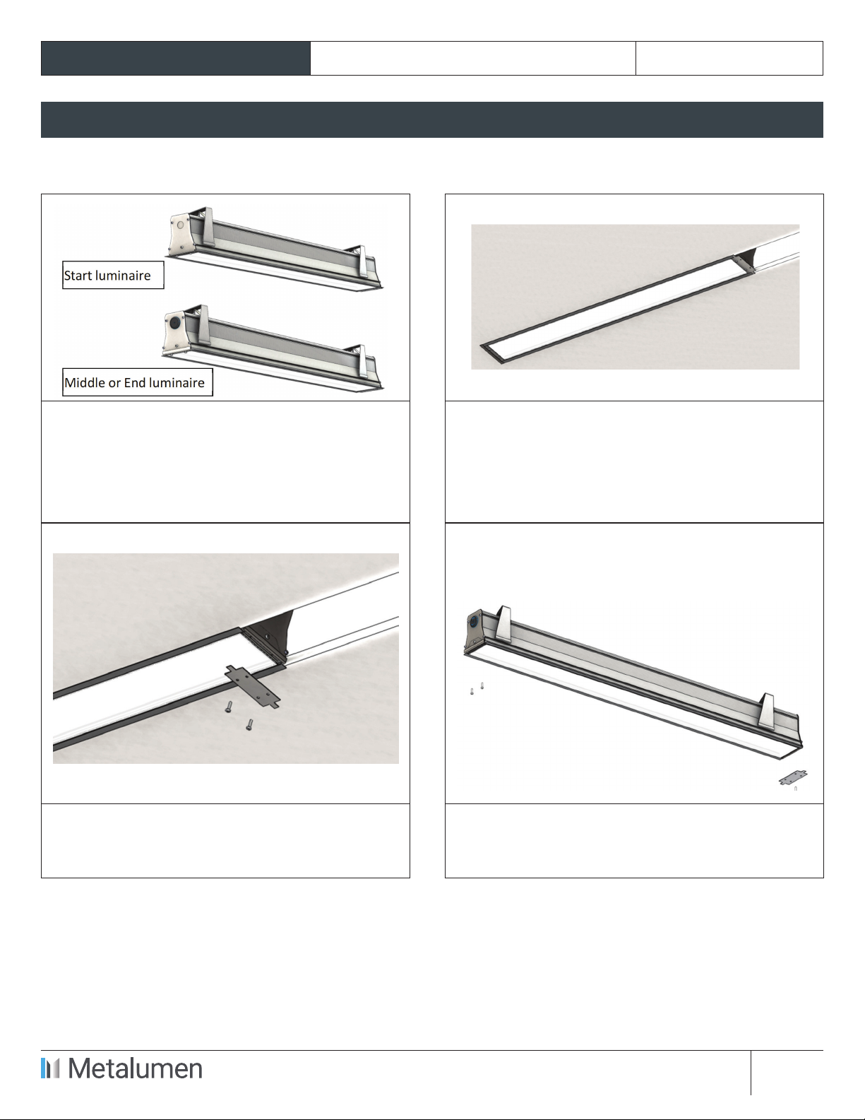
STEP-BY-STEP INSTRUCTIONS
STEP 1. Remove xture packaging; note marked
supply wires coming out at one end of the
Start luminaire and wires for row mounting
connections at the opposite end. Note wires for
row mounting come out thru a protective rubber
grommet.
STEP 2. Install Start luminaire following standard
installation instructions. Do not apply power to
the xture.
STEP 3. Make sure end screws (E) and joiner
plate (F) are removed from the Start xture.
Keep all parts.
STEP 4. Remove end screws (E), end plate (C) and
joiner plate (F) from Middle or End xture. Keep all
parts.
Specications and design subject to change without notice.
570 Southgate Drive, Guelph, Ontario N1G 4P6
Mailing Address: P.O. Box 1779
Guelph, Ontario N1H 6Z9
T 1.800.621.6785 | T 519.822.4381 | F 519.822.4589
www.metalumen.com IS-0260-02 rev.00
PAGE 4 OF 7
JOINING INSTRUCTIONS RM4DOD Recessed RAIL 4
STEP-BY-STEP INSTRUCTIONS
STEP 5. Remove lens (D) from the next xture to
be installed in the row (Middle or End luminaire).
Starting at one end; pull one side rst, rotate
and detach. Keep lens.
STEP 6. Remove reector mounting screws and
reector. Note xtures with optional emergency
pack have a test switch and indicator light
mounted on the reector.
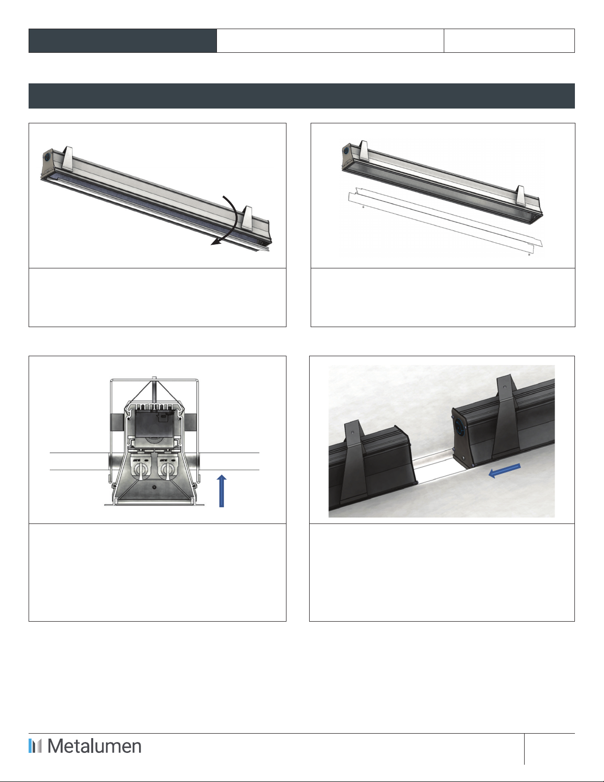
STEP 7. Make sure all mounting brackets (B)
are parallel to the luminaire enclosure (A) and
insert xture through the opening in the ceiling.
Bring xture close to the Start xture (already
installed).
STEP 8. Route electrical supply from Start xture
through the rubber protective plug at the end of
the xture to be installed. Pierce plug membrane
in the middle of the plug and push/pull wires
inside the Middle/End xture. Insert xture
completely through the ceiling opening and join
luminaires together.
Specications and design subject to change without notice.
570 Southgate Drive, Guelph, Ontario N1G 4P6
Mailing Address: P.O. Box 1779
Guelph, Ontario N1H 6Z9
T 1.800.621.6785 | T 519.822.4381 | F 519.822.4589
www.metalumen.com IS-0260-02 rev.00
PAGE 5 OF 7
JOINING INSTRUCTIONS RM4DOD Recessed RAIL 4
STEP-BY-STEP INSTRUCTIONS
STEP 9. Begin tightening the mounting screws.
Mounting brackets will swing out and retain
the luminaire in place. Continue to tighten the
screws until the luminaire anges are ush with
the ceiling.
STEP 10. Perform electrical wiring inside the
xture and re-attach reector with (2) mounting
screws. Optional emergency ballast must be fed
from the same branch circuit as the AC ballast.
STEP 11. Install lamp(s). STEP 12. Re-attach lens. Start with one side
rst and close the other side starting from the
corner. Make sure lens gaskets are in place and
compressed between lens and xture housing.
Specications and design subject to change without notice.
570 Southgate Drive, Guelph, Ontario N1G 4P6
Mailing Address: P.O. Box 1779
Guelph, Ontario N1H 6Z9
T 1.800.621.6785 | T 519.822.4381 | F 519.822.4589
www.metalumen.com IS-0260-02 rev.00
PAGE 6 OF 7
JOINING INSTRUCTIONS RM4DOD Recessed RAIL 4
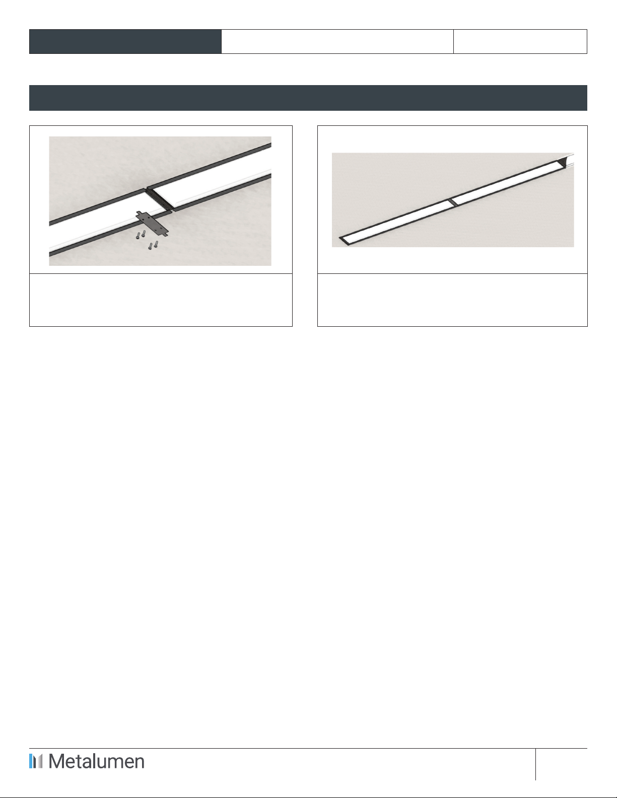
STEP-BY-STEP INSTRUCTIONS
STEP 13. Re-attach joiner plate with (4) end
screws.
STEP 14. Joined luminaires. Complete remaining
xtures installation as needed.
Specications and design subject to change without notice.
570 Southgate Drive, Guelph, Ontario N1G 4P6
Mailing Address: P.O. Box 1779
Guelph, Ontario N1H 6Z9
T 1.800.621.6785 | T 519.822.4381 | F 519.822.4589
www.metalumen.com IS-0260-02 rev.00
PAGE 7 OF 7
JOINING INSTRUCTIONS RM4DOD Recessed RAIL 4
Fixture size and recommended ceiling/canopy opening Diagram:
Other manuals for RAIL 4
1
This manual suits for next models
1
Table of contents
Other Metalumen Lighting Equipment manuals


