BEFORE YOU BEGIN
Yourantennahaselementswhichareresonantinthe30-54MHz,
108-174 MHz, 450-470 MHz, 470-512 MHz, and 800-912 MHz
bands.They work togetherto give youfrequency coverage from
30MHzto1300MHz.Beforeyoubeginassembly,readthismanual
andthe Consumer ProductSafety Commission information.For
your safety and convenience, plan each step of the installation
and purchase the necessary hardware in advance. The order in
whichyouperform the steps andthehardwarerequireddepends
on the mounting and connection methods you choose. Your an-
tenna comes complete with a matching transformer, 50 feet of
RG-6coaxial cable withaF-to-BNC adapter.
We recommend two people assemble the entire antenna on the
ground, then mount the assembled antenna on the mast. The
followingsteps are required toassemble your antenna.
Warning: When you install your antenna, use extreme caution.
If the antenna starts to fall, let it go! It could contact overhead
power lines. If the antenna touches the power line, contact with
the antenna, mast, cable, or guy wires can cause electrocution
and death. Call the power company to remove the antenna. Do
not attempt to remove it yourself.
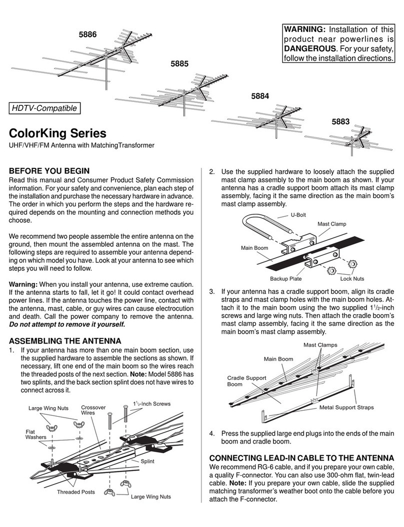
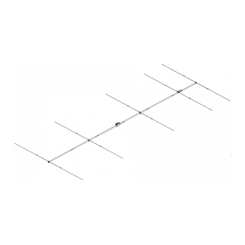
ST2
Omni-directionalOutdoorScannerAntenna
withMatchingTransformerand
50’ofRG-6 Coaxial Cable, withF-to-BNCadapter
ST2
ASSEMBLING THE ANTENNA
1. Usethesuppliedhardwareto looselyattachthesuppliedmast
clamp assembly to the main boom as shown.
2. Press the supplied large end plugs into the main boom.
3. Holdthecenterand front main boomelementsnearthe pivot
points and unfold them until they snap into the locking plas-
ticsuppport insulators. Positionthe legs onthe smallerfront
elements outward, so they line up with the elements under
them. Pull the swivel bracket elements outward until they
snap into the swivel brackets’ tabs.
WARNING: Installation of this
product near powerlines is
DANGEROUS.For yoursafety,
followthe installationdirections.
New Improved
Heavy-Duty!
