Solid Alliance eROU User manual

Confidential & Proprietary 2/20
REVISION HISTORY
Version
Issue Date
No. of
Pages
Initials
Details of Revision Changes
V 1.0
March 09, 2020
Original
V 1.1
Jun 23,2020
eROUa_682335 Add
V 1.2
Jan 25,2022
eROUa_682335_R Add
Technical Support
SOLiD serial numbers must be available to authorize technical support and/or to establish a return
authorization for defective units. The serial numbers are located on the back of the unit, as well as on the
box in which they were delivered. Additional support information may be obtained by accessing the SOLiD
This manual is produced by Global Business Division Business Team Printed in Korea.

Confidential & Proprietary 3/20
Contents
Section1 Safety & Certification Notice .................................................................................. 4
Section2 System configuration and Functions ...................................................................... 9
2.1 eROU(edge Remote Optic Unit) ..........................................................................9
2.1.1 Specifications of eROU .............................................................................. 11
2.1.2 Port on eROU ........................................................................................... 12
2.1.2.1 Functions................................................................................................. 12
2.2 AC/DC Adaptor information ............................................................................. 14
Section3 System Installation ............................................................................................... 15
3.1 eROU Installation............................................................................................ 15
3.1.1 eROU Enclosure installation ....................................................................... 15
3.1.2 eROU(External Antenna) Mount Installation................................................. 18
3.1.3 Installation Cable Gland............................................................................. 19
3.1.4 Power cabling........................................................................................... 20

Confidential & Proprietary 4/20
Section1
Safety & Certification Notice

Confidential & Proprietary 5/20
“Only qualified personnel should handle the DAS equipment. Any person involved in installation
or service of the DAS should understand and follow these safety guidelines.”
- Obey all general and regional installation and safety regulations relating to work on high voltage
installations, as well as regulations covering correct use of tools and personal protective equipment.
- The power supply unit in repeaters contains dangerous voltage level, which can cause electric shock.
Switch the mains off prior to any work in such a repeater. Any local regulations are to be followed when
servicing repeaters.
- eROU equipment is exclusive to the indoor.
- Use this unit only for the purpose specified by the manufacturer. Do not carry out any modifications or
fit any spare parts which are not sold or recommended by the manufacturer. This could cause fires,
electric shock or other injuries.
- Any DAS system or Fiber BDA will generate radio (RF) signals and continuously emit RF energy. Avoid
prolonged exposure to the antennas. SOLiD recommends maintaining a 60 cm minimum clearance from
the antenna while the system is operating.
- Do not operate this unit on or close to flammable materials, as the unit may reach high temperatures
due to power dissipation.
- Do not use any solvents, chemicals, or cleaning solutions containing alcohol, ammonia, or abrasives on
the DAS equipment. Alcohol may be used to clean fiber optic cabling ends and connectors.
- To prevent electrical shock, switch the main power supply off prior to working with the DAS System or
Fiber BDA. Never install or use electrical equipment in a wet location or during a lightning storm.
- Do not look into the ends of any optical fiber or directly into the optical transceiver of any digital unit.
Use an optical spectrum analyzer to verify active fibers. Place a protective cap over any radiating
transceiver or optical fiber connector to avoid the potential of radiation exposure.
- Allow sufficient fiber length to permit routing without severe bends.
- For pluggable equipment, make sure to install the socket outlet near the equipment so that it is easily
accessible.
- A readily accessible disconnect device shall be incorporated external to the equipment.
- This power of this system shall be supplied through wiring installed in a normal building.
If powered directly from the mains distribution system, it shall be used additional protection, such as
overvoltage protection device

Confidential & Proprietary 6/20
- Only 50 ohm rated antennas, cables and passive equipment shall be used with this remote. Any
equipment attached to this device not meeting this standard may cause degradation and unwanted
signals in the bi-directional system. All components connected to this device must operate in the
frequency range of this device.
- Only 50 ohm rated antennas, cables and passive components operating from 150 - 3 GHz shall be used
with this device.
- The head end unit must always be connected to the Base Station using a direct cabled connection. This
system has not been approved for use with a wireless connection via server antenna to the base station.
- Access can only be gained by SERVICE PERSONS or by USERS who have been instructed about the
reasons for the restrictions applied to the location and about any precautions that shall be taken; and
- Access is through the use of a TOOL or lock and key, or other means of security, and is on trolled by the
authority responsible for the location.
- Notice! Be careful not to touch the Heat-sink part due to high temperature.
- Signal booster warning label message should include
- IC Booster warning label message should include
WARNING: This is NOT a CONSUMER device. It is designed for installation by an
installer approved by an ISED licensee. You MUST have an ISED LICENCE or the
express consent of an ISED licensee to operate this device

Confidential & Proprietary 7/20
- Certification
FCC: This equipment complies with the applicable sections of Title 47 CFR Parts 15,22,24,27 and
90
- Use of unauthorized antennas, cables, and/or coupling devices not conforming with ERP/EIRP
and/or indoor‐only restrictions is prohibited.
- Home/ personal use are prohibited.
UL/CUL: This equipment complies with UL and CUL 62368-1 Standard for safety for information
technology equipment,including electrical business equipment
FDA/CDRH: This equipment uses a Class 1 LASER according to FDA/CDRH Rules.This product
conforms to all applicable standards of 21 CFR Chapter 1, Subchaper J, Part 1040
FCC Part 15.105 statement
This equipment has been tested and found to comply with the limits for a Class A digital device,
pursuant to part 15 of the FCC Rules. These limits are designed to provide reasonable protection
against harmful interference when the equipment is operated in a commercial environment. This
equipment generates, uses, and can radiate radio frequency energy and, if not installed and used
in accordance with the instruction manual, may cause harmful interference to radio
communications. Operation of this equipment in a residential area is likely to cause harmful
interference in which case the user will be required to correct the interference at his own
expense.
FCC Part 15.21 statement
Any changes or modifications not expressly approved by the party responsible for compliance
could void the user's authority to operate this equipment.
RF Exposure Statement
The antenna(s) must be installed such that a minimum separation distance of at least 60 cm is
maintained between the radiator (antenna) and all persons at all times. This device must not
be co-located or operating in conjunction with any other antenna or transmitter.
(Max. gain : 17 dBi)
.

Confidential & Proprietary 8/20
RSS-GEN (6.8 Transmit antenna)
Under Industry Canada regulations, this radio transmitter may only operate using an antenna
of a type and maximum (or lesser) gain approved for the transmitter by Industry Canada. To
reduce potential radio interference to other users, the antenna type and its gain should be so
chosen that the equivalent isotropically radiated power (e.i.r.p.) is not more than that
necessary for successful communication. (Max. gain : 17 dBi)
Conformément à la réglementation d’Industrie Canada, le présent émetteur radio peut
fonctionneravec une antenne d’un type et d’un gain maximal (ou inférieur) approuvé pour
l’émetteur par Industrie Canada. Dans le but de réduire les risques de brouillage radioélectrique
à l’intention desautres utilisateurs, il faut choisir le type d’antenne et son gain de sorte que la
puissance isotroperayonnée quivalente (p.i.r.e.) ne dépassepas l’intensité nécessaire à
l’établissement d’une communication satisfaisante. (Max. gain : 17 dBi)
RF Radiation Exposure
This equipment complies with RF radiation exposure limits set forth for an uncontrolled
environment. This equipment should be installed and operated with a minimum distance of 60
cm between the radiator and your body. This transmitter must not be co-located or operating
in conjunction with any other antenna or transmitter. RF exposure will be addressed at time of
installation and the use of higher gain antennas may require larger separation distances.
RSS-102 RF Exposure
L’antenne (ou les antennes) doit être installée de façon à maintenir à tout instant une distance
minimum de au moins 60cm entre la source de radiation (l’antenne) et toute personne
physique. Cet appareil ne doit pas être installé ou utilisé en conjonction avec une autre antenne
ou émetteur.

Confidential & Proprietary 9/20
Section2
System configuration and Functions
2.1 eROU (edge Remote Optic Unit) & eROUa
The eROUa is a coverage system for in-building services delivering voice and data in high quality and for
seamlessly. The system covers general public institutions and private facilities.
*Shopping malls
*Hotels
*Campus areas
*Airports
*Clinics
*Subways
*Multi-use stadiums, convention centers, etc.
eROU receives TX optical signals from eHUB and converts them into RF signals. The converted RF signal is
radiated to the antenna port via the AMP and Multiplexer. When receiving RX signals through the antenna
port, this unit filters out-of-band signals in a corresponding Multiplexer and sends the results to OPTIC to
make electronic-optical conversion of them. After converted, the signals are sent to a upper device of
eHUB.
For this application, eROUa receives RF signals from eROU. The received RF signals are radiated through
the AMP and multiplexer to the antenna ports. When the device receives an RX signal through the antenna
port, it filters out-of-band signals from the appropriate multiplexer and transmits the results to the RF
signal. The signal is transmitted to the upper unit of the eHUB.
Figure 1. eROU & eROUa Configuration Diagram
CASCADE_KIT
eROU
cROU (If extended)
eROUa
External PSU
External PSU
Confidential & Proprietary 10/20
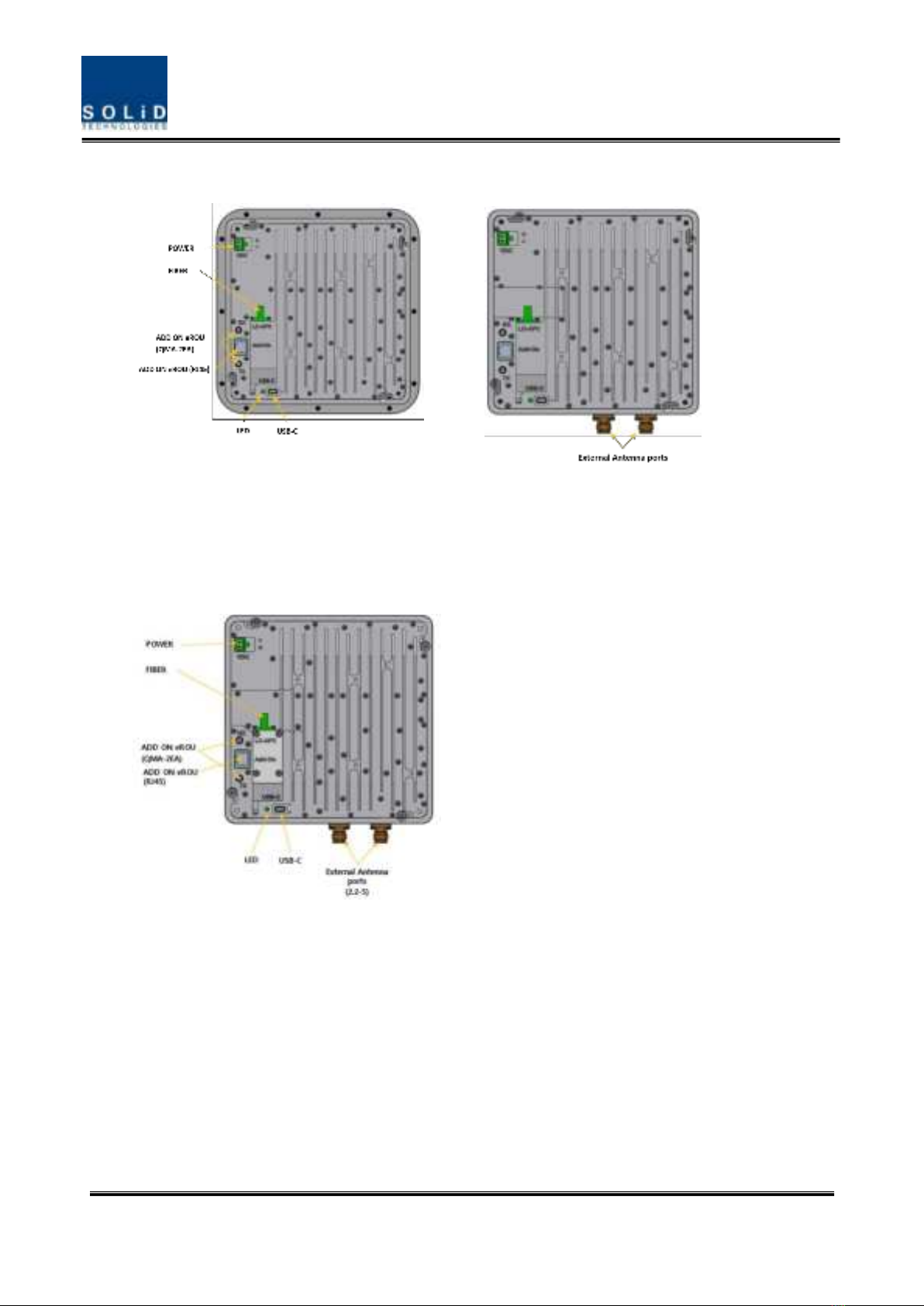
<Integrated Antenna> <External Antenna>
Figure 2. eROU outer Look
<Only External Antenna>
Figure 3. eROUa outer Look
Confidential & Proprietary 11/20
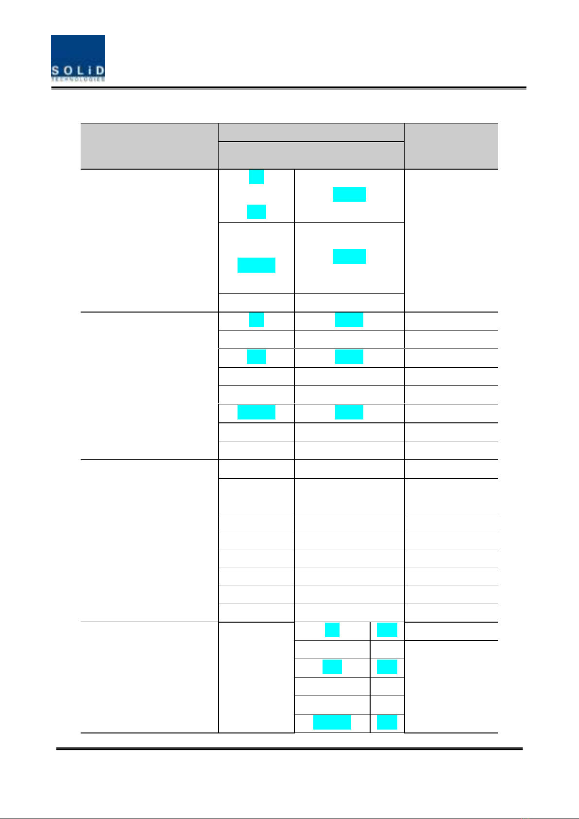
Specifications of eROUa
Item
Spec.
Remark
eROU
The rated mean output Power
per band
600
700LTE_FN
8085
+19dBm
1900P
AWS13
2300WCS
2500_100TDD
+23dBm
3500CBRS
N/A
The nominal downlink
bandwidth
600
35MHz
700LTE_FN
39MHz
8085
32MHz
1900P
65MHz
AWS13
70MHz
2300WCS
10MHz
2500_100TDD
194MHz
3500CBRS
N/A
The nominal uplink bandwidth
600
35MHz
700LTE_FN
700FN B1 : 17MHz
700FN B2 : 21MHz
8085
32MHz
1900P
65MHz
AWS13
70MHz
2300WCS
10MHz
2500_100TDD
194MHz
3500CBRS
N/A
The nominal passband gain
Downlink
600
61dB
700LTE_FN
63dB
8085
58dB
1900P
67dB
AWS13
67dB
2300WCS
69dB

Confidential & Proprietary 12/20
2500_100TDD
67dB
3500CBRS
N/A
Uplink
600
8085
3500CBRS
52dB
2300WCS
48dB
700LTE_FN
1900P
AWS13
2500_100TDD
45dB
Input/ Output Impedance
50 ohm
Weight
2.6 kg(Internal)
Common Part
3.0 kg(External)
Power consumption
35W
Temperature range
-5°C to +50°C
Ambient Temperature
Humidity Range
5% ~ 90%
Non-condensing
Sealing (Remote Unit)
IEC/UL/CSA 62368-1
Size(mm)
220 x 220 x 90
Integrated Antenna
200 x 200 x 73
External Antenna
2.1.1 Port on eROU & eROUa
2.1.1.1 Functions
<Integrated Antenna> <External Antenna>
Figure 4. The name of each port on eROU

Confidential & Proprietary 13/20
<External Antenna>
Figure 5. The name of each port on eROUa
Confidential & Proprietary 14/20
2.2 AC/DC Adaptor information
Manufacturer
SHENZHEN HONOR ELECTRONIC
Model name
ADS-65DI-48-1 48065E
Specification
Input range 100-240V, 50/60Hz
Output range 48Vdc 1.35A / 64.8W
This product is intended to be supplied by a Listed Switching Adapter marked “Class 2” or
“LPS” or “PS2” and rated from 100 - 240V~; 50/60HZ; 1.5A max.
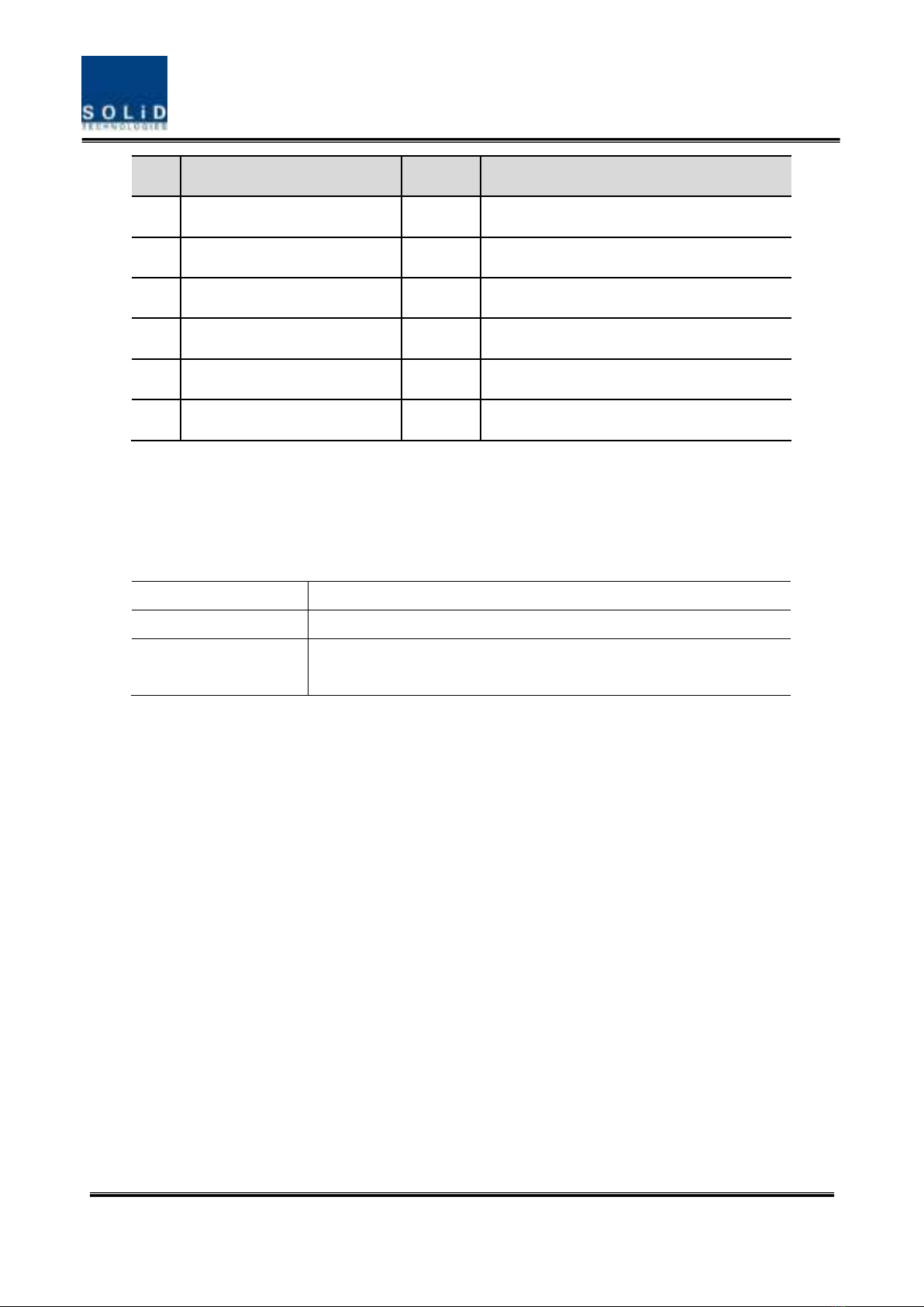
No
Port
Quantity
Remark
1
Optical Port
1EA
LC/APC
2
ANTENNA PORT(External Only)
1EA
2.2-5 type female
3
Power IN
1EA
Terminal_Block_CONN_2P(TLPS-302V-02P-G)
4
ADD ON eROU Port
2EA
QMA-type female
5
ADD ON eROU Port
1EA
RJ45
6
USB Port
1EA
USB-C Type

Confidential & Proprietary 15/20
Section3 System Installation
3.1 eROU Installation
The following table shows the required accessories and tools for installing eROU.
No
Tools
Q’ty
Specification
Remark
1
1
(+), Ø3.0
Length is more than 20mm
For fixing
3.1.1 eROU Enclosure installation
The eROU can be mounted on a wall or ceiling.
and divided into the version of External Antena and the version of Internal Antena.
Figure 3. eROU appearance (Left : External Antenna, Right : Internal Antenna)

Confidential & Proprietary 16/20
Figure 4. Dimension used to install eROU (internal)
Figure 3. Dimension used to install eROU (external)

Confidential & Proprietary 17/20
Figure 4. Dimension used to install eROUa (external)

Confidential & Proprietary 18/20
3.1.2 eROU & eROUa (External Antenna) Mount Installation

Confidential & Proprietary 19/20
3.1.3 Installation Cable Gland
3.1.3.1 eROU
3.1.3.2 Combine of eROU and cROU (extended type)
From/To eHUB

Confidential & Proprietary 20/20
3.1.3.3 Combine of eROU and eROUa
3.1.4 Power cabling
1. The eROU receives DC power from the eHub or external adapter.
2. Cable length between eHub and eROU supports up to 1 km.(Cable specifications
recommend AWG14 and Cable type shall be marked “CL2”.)
3. If the maximum length between the eHub and the eROU is exceeded, the use of
the External Adapter is recommended.
** Adaptor is extra purchases. Specified below shall be used only adapter.
This manual suits for next models
1
Table of contents
Other Solid Network Hardware manuals


Popular Network Hardware manuals by other brands

Grandstream Networks
Grandstream Networks GRP261 Series Administration guide

TRENDnet
TRENDnet TEW-441PC - 108Mbps Wireless PC Card... Quick installation guide

Honeywell
Honeywell Rae SensorRAE 4R+ user guide

D-Link
D-Link DSN-500 Software user's guide

SCW
SCW NWP5204P4 user manual

TP-Link
TP-Link TL-WPA8631P Quick installation guide


