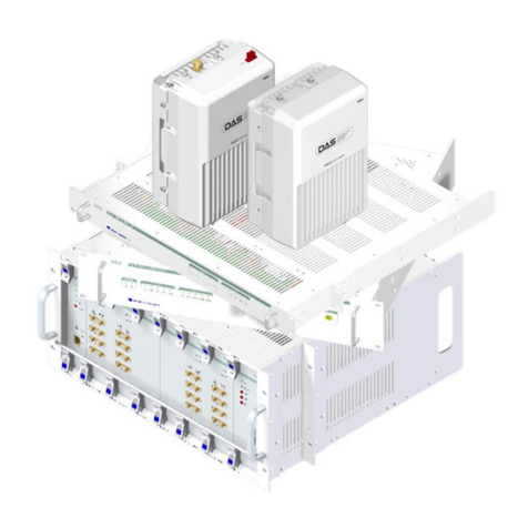
Solid GENESIS DAS Instruction Manual

©2019 SOLiD, Inc. All Rights Reserved. Confidential & Proprietary. Page 1
GENESISTM DAS
Installation and Maintenance
Version 0.0 Feb. 2019

GENESISTM DAS Operation Manual - Version 0.0 – Jan. 2019
©2019 SOLiD, Inc. All Rights Reserved. Confidential & Proprietary. Page 2
Copyright
All rights are reserved ©2019 SOLiD. Confidential and proprietary. Information contained in this document
is company private to SOLiD and should not be modified, used, copied, reproduced or disclosed in whole
or in part without the written consent of SOLiD.
Trademark Information
No right, license, or interest to SOLiD trademarks is granted here. By using this document, you agree not
to assert any right, license, or interest with respect to such trademark. Other product names mentioned in
this manual are used for identification purposes only and may be trademarks or registered trademarks of
their respective companies.
Disclaimer of Liability
The contents of this document, including graphics and screenshots, are current as of the date of
publication. SOLiD reserves the right to change the contents without prior notice. In no event shall SOLiD
be liable for any damages resulting from loss of data, loss of use or loss of profits. SOLiD further
disclaims any and all liability for indirect, incidental, special, consequential or other similar damages. This
disclaimer of liability applies to all products, publications and services during and after the warranty
period.
Getting Support and Providing Feedback
To authorize technical support or to establish a return authorization for defective units, make sure you
have the SOLiD serial numbers available. Serial numbers are located on the back of the unit, as well as
on the box in which it was delivered. Contact SOLiD for additional support information:
For Central & Latin America Region: CALA.support@solid.co.kr
For Asian Pacific Region excluding Korea: APAC.s[email protected]r
For Europe, Middle East & Africa: EMEA.support@solid.co.kr

GENESISTM DAS Operation Manual - Version 0.0 – Jan. 2019
©2019 SOLiD, Inc. All Rights Reserved. Confidential & Proprietary. Page 3
Revision History
Revision
Issue Date
Section
Changes

GENESISTM DAS Operation Manual - Version 0.0 – Jan. 2019
©2019 SOLiD, Inc. All Rights Reserved. Confidential & Proprietary. Page 4
Contents
Safety & Certification Notice ..................................................................................7
System Overview.....................................................................................................9
2.1 Purpose ......................................................................................................................................... 9
2.2 System Overview ........................................................................................................................ 11
2.2.1 System Components and Network Topology ................................................................ 11
2.2.2 System Capacities ......................................................................................................... 12
System Specifications ..........................................................................................13
3.1 General Specifications ................................................................................................................ 13
3.2 Ports and Environment Specifications ........................................................................................ 13
3.3 Downlink Specifications .............................................................................................................. 14
3.4 Uplink Specifications ................................................................................................................... 15
System Configuration and Functions..................................................................16
4.1 Low power Radio Node (LRN) .................................................................................................... 16
4.1.1 LRN Specifications ........................................................................................................ 16
4.1.2 LRN Functions and Description ..................................................................................... 17
4.1.3 LRN Front and Rear Panel ............................................................................................ 20
4.1.3.1 Front Panel ................................................................................................................. 20
4.1.3.2 Rear Panel .................................................................................................................. 20
4.1.4 LRN Installation.............................................................................................................. 21
System Operation..................................................................................................28
5.1 LRN Parameters ......................................................................................................................... 28
FCC/IC User Warning ............................................................................................30

GENESISTM DAS Operation Manual - Version 0.0 – Jan. 2019
©2019 SOLiD, Inc. All Rights Reserved. Confidential & Proprietary. Page 5
List of Illustrations
Figure 2.1 GENESISTM Network Topology ................................................................................................. 11
Figure 4.1 LRN Front, Side and Rear Views ............................................................................................... 16
Figure 4.2 LRN Appearance ....................................................................................................................... 17
Figure 4.3 LRN Front Panel View ............................................................................................................... 20
Figure 4.4 LRN Rear Panel View ................................................................................................................ 20
Figure 4.5 LRN Installation Clearance ........................................................................................................ 21
Figure 4.6 LRN Power Cabling ................................................................................................................... 24
Figure 4.7 LRN SFP Ports .......................................................................................................................... 25

GENESISTM DAS Operation Manual - Version 0.0 – Jan. 2019
©2019 SOLiD, Inc. All Rights Reserved. Confidential & Proprietary. Page 6
Glossary of Terms
Acronyms and abbreviation used in this manual are shown in the table below.
Abbreviation
Description
UPOI
Universal Point of Interface
UPIU
UPOI Point of Interface Unit
DAU
Distribution & Aggregation Unit
DRFU
DAU RF Unit
DDTU
DAU Digital Transceiver Unit
DPSU
DAU Power Supply Unit
DFAN
DAU FAN
DCU
DeCode Unit
HOU
Hub Optic Unit
HODTU
HOU Digital Transceiver Unit
HOPSU
HOU Power Supply Unit
HOFAN
HOU FAN
EPSU
Expansion Power Supply Unit
LRN
Low power Radio Node
RBU
RN Base Unit
LPMU
LRN Power Amplifier & Multiplexer Unit

GENESISTM DAS Operation Manual - Version 0.0 – Jan. 2019
©2019 SOLiD, Inc. All Rights Reserved. Confidential & Proprietary. Page 7
Safety & Certification Notice
“Only qualified personnel are allowed to handle this unit. Read carefully and understand all the
warning labels attached in this user manual”
Any personnel involved in installation, operation or service of the SOLiD repeaters must
understand and comply the following:
Understand all general and regional installation and safety regulations relating to work on high
voltage installations, as well as regulations covering correct use of tools and personal protective
equipment.
The power supply unit in repeaters contains dangerous voltage level, which can cause electric
shock. Switch the mains off prior to any work in such a repeater. Any local regulations are to be
followed when servicing repeaters.
The repeater cover should be (door) securely fastened in open position, e.g. by tying it up, at
outdoor work in order to prevent door from slamming due to wind causing bodily harm or
damage.
Use this unit only for the purpose specified by the manufacturer. Do not carry out any
modifications or fit any spare parts which are not sold or recommended by the manufacturer.
This could cause fires, electric shock or other injuries.
Any repeater, including this repeater, will generate radio signals and thereby give rise to
electromagnetic fields that may be hazardous to the health of any person who is extensively
exposed to the signals at the immediate proximity of the repeater and the repeater antennas.
Due to power dissipation, repeater may reach a very high temperature. Do not operate this unit
on or close to flammable materials.
Do not use any solvents, chemicals, or cleaning solutions containing alcohol, ammonia, or
abrasives.
For pluggable equipment, the socket-outlet shall be installed near the equipment and shall be
easily accessible.
This power of this system shall be supplied through wiring installed in a normal building. If
powered directly from the mains distribution system, it shall be used additional protection, such
as overvoltage protection device.
Round terminals located on the rear of a 1.0mm2 (16AWG) or more wires using permanently
connected to earth.
WARNING
This is a class A product. In domestic environment, this product may cause radio interference in which
cause the user may be required to take adequate measures.
Home/ personal use are prohibited.

GENESISTM DAS Operation Manual - Version 0.0 – Jan. 2019
©2019 SOLiD, Inc. All Rights Reserved. Confidential & Proprietary. Page 8
Rotating fan Blade
Can cause serious injury or pain. Keep hands clear. Turn off and lock-out unit before servicing.
CAUTION
Do Not Open Except at Approved Field Force Protective Work Station.

GENESISTM DAS Operation Manual - Version 0.0 – Jan. 2019
©2019 SOLiD, Inc. All Rights Reserved. Confidential & Proprietary. Page 9
System Overview
GENESISTM is a coverage system for indoor and outdoor services delivering voice and data in high
quality and for seamlessly.
As a distributed antenna system, it provides analog and digital phone systems that are served in multiple
bands. The system covers general public institutions and private facilities.
Small building
Shopping Malls
Hotels
Campus areas
Airports
Subways
Multi-use stadiums, convention centers, etc.
The system helps to improve indoor/outdoor radio environments in poor condition and makes better RSSI
and Ec/Io. By providing communication services at every corner of buildings, the system enables users to
make a call at any site.
The GENESISTM system supports communication standards and public interface protocols in worldwide
use.
Frequencies: 700MHz, 800MHz, 1900MHz, 2100MHz, 2300MHz, 2500MHz, etc.
Technologies: GSM, EDGE, CDMA2000, 1XEVDO, WCDMA, LTE, APCO 25, etc.
GENESISTM is in modular structure per frequency band. To provide desired frequency in target venue, all
you need to do is to insert a corresponding frequency module into each unit. As it delivers multiple signals
with one optical cable, the system, in one-body type, does not require additional facilities whenever new
frequency is added.
The head-end unit must always be connected to the Base Station using a direct cabled connection. This
system has not been approved for use with a wireless connection via server antenna to the base station.

GENESISTM DAS Operation Manual - Version 0.0 – Jan. 2019
©2019 SOLiD, Inc. All Rights Reserved. Confidential & Proprietary. Page 10
The system is featured with the followings:
Universal One Digital transport DAS platform
Cover small to large venues with Low power remotes
Common Head-End for various remote types
Low power remotes to transport signals over an optical fiber
SOLiD GENESISTM is a robust, flexible, expandable, and customizable cellular coverage solution for
multiple operators and technologies as universal platform. It also supports enterprise, outdoor and indoor
coverage applications.
Excellent Architecture & Performance
Advanced platform of mix and match topology - any RN connection
Near-far mitigation functions - digital filtering and fast ALC function
Low power consumption - high linearization technology
Flexible & Scalable Deployment
Support any band combination - simply plug-in as your network grows
Modular plug-in and play structure - easy management and expandable
High Capacity & Evolution
Sector switching (cell split/combine) - software controlled based on user pre-defined profiles
Smooth LTE migration ready for all bands - technology refarming
Easy Management
Embedded DMS, server DMS and cloud EMS
High-quality user experience(visibility, intuitive troubleshooting, auto commissioning, and
reports)
Single EMS for managing LRN
Automatic node discovery
Easy-set
Flexible power splitting

GENESISTM DAS Operation Manual - Version 0.0 – Jan. 2019
©2019 SOLiD, Inc. All Rights Reserved. Confidential & Proprietary. Page 11
2.2.1 System Components and Network Topology
GENESISTM product series are that one common head-end delivers a more flexible network configuration.
Universal Point of Interface (UPOI): Attenuate high power signal from RAN and transport into DAU
Distribution & Aggregation Unit (DAU): Interface with analog RANs. Convert RF to digital and digital
into RF signals, and distributes digital signals to HOU via optical fiber
Decode Unit (DCU): Interface with DAU via UTP cable (CAT5). Decode signals input to DAU, and
Decode information is used for system ‘Auto Setup’
Hub Optic Unit (HOU): Interface with LRN via optical cable. Support the daisy chain of HOU to reduce
the number of optical fiber cables
Expansion Power Supply Unit (EPSU): Interface with HOU via D-SUB cable. Supply DC 57V to LRN.
Up to 24 LRNs can be powered via power cable (supported AWG 14 to 24)
Low Power Radio Node (LRN): Receive signal and power via optical cable and power cable (supported
AWG 14 to 24) from HOU
The following shows GENESISTM network topology.
Figure 2.1 GENESISTM Network Topology

GENESISTM DAS Operation Manual - Version 0.0 – Jan. 2019
©2019 SOLiD, Inc. All Rights Reserved. Confidential & Proprietary. Page 12
2.2.2 System Capacities
UPOI can support up to eight (8) interface module slots and each slot supports three (3) input
ports.
DAU can have up to six (6) RF interface module slots and each slot supports four (4) input ports.
DAU can support up to two (2) Expansion DAUs.
Adding two (2) Expansion DAUs to the main DAU, a system can support up to seventy-two (72)
cell interfaces.
Main DAU can drive up to sixteen (16) HOUs
HOU can drive up to eight (8) LRNs via optical cables.
LRN can support up to six (6) RF band modules.

GENESISTM DAS Operation Manual - Version 0.0 – Jan. 2019
©2019 SOLiD, Inc. All Rights Reserved. Confidential & Proprietary. Page 13
System Specifications
Item
Specification
Remark
Frequency Band
700FB
8085
1900
AWS13
2300W
2500TDD
Instantaneous
Bandwidth
39MHz
32MHz
65MHz
70MHz
10MHz
190MHz
Technology
LTE
GSM, UMTS,
LTE, CDMA
GSM, UMTS,
LTE, CDMA
UMTS, LTE
LTE
LTE
Transmission Capacity
10Gbps
Transmission Distance
<10km@Optic, <100m@Power Cable(AWG 14 to 24)
VSWR
< 1.5 : 1@DAU, <1.8 : 1@LRN Uplink
Frequency Error
±0.01ppm
System Delay
< 8usec, 1.0usec raise whenever node is added in daisy chain
Item
UPOI
DAU
DCU
HOU
EPSU
LRN
Input Connector
4.3-10_F(24)
QMA_F(24): DL/UL
QMA_F(24): UL
MCX_F(24)_Mon
QMA(24):
DAU
Optic(1): DAU
-
Optic(1): HOU
Output
Connector
QMA_F(24)
Optic(2): E-DAU
Optic(8): HOU
RJ45(1):
DAU
Optic(1): HOU
Optic(8): LRN
-
NEX-10(1):
External ANT
Input Voltage
+12V from
DAU
90 ~ 264VAC or
-42 ~ - 56VDC
90 ~ 264VAC
90 ~ 264VAC
90 ~
264VAC
DC 57V from
HOU
IP Rating
IP20
IP20
IP20
IP20
IP20
IP20 or IP66
(OPTION)
Cooling
FAN Forced
FAN Forced
Natural
FAN Forced
FAN
Forced
Natural

GENESISTM DAS Operation Manual - Version 0.0 – Jan. 2019
©2019 SOLiD, Inc. All Rights Reserved. Confidential & Proprietary. Page 14
Operating Temp.
-5 ~ +45°C
-5 ~ +45°C
-5 ~ +45°C
-5 ~ +45°C
-5 ~
+45°C
-25 ~ +45°C
Size(WxHxD),
mm
19” x 3U x 475
19” x 3U x 475
19” x 1U x
420
19” x 1U x
371.4
19” x 1U
x 374
390 x 300 x 74
(8.7ℓ)
Normal Noise,
dBA
64
61
NA
60
65
NA
Watt, w
25
370
36
55+800(LRN)
800 X 3
75
Weight, kg
31
17.5
4.36
4.15
10.1
7.5
Item
Specification
Remark
Ripple
< 4dB
Peak to peak
Input level
UPOI
+47 ~ +30dBm
Max.+50dBm/No-destructive
DAU
+30 ~ 0dBm
Max.+33dBm/No-destructive
Output power
LRN
20dBm(>1GHz), 15dBm(<1GHz), 17dBm(2300W Band)
Per band
System Gain
LRN
-10 ~ 20dB(>1GHz), -15 ~ 15dB(<1GHz), -13 ~ 17dB(2300W Band)
Gain Control
0 ~ 50dB
DAU
Output Control
0 ~ 25dB
RN
Out of Band Gain
3GPP TS 25 106 Section 8 and 3GPP TS 36 106
Unwanted Emission
Spurious Emission
Category B
ACLR
LTE
> 35dB @ Fc±5MHz
UMTS
> 35dB @ Fc±5MHz
EVM
LTE
< 3.5%
256QAM
UMTS
< 12.5%
CDMA
< 0.912(Rho)
GSM
< 5°(phase error), < 20°peak(RMS)

GENESISTM DAS Operation Manual - Version 0.0 – Jan. 2019
©2019 SOLiD, Inc. All Rights Reserved. Confidential & Proprietary. Page 15
Item
Specification
Remark
Ripple
< 4dB
Peak to peak
Input Level
Nominal -40dBm
Max. -38dBm @ No- destructive by ALC function
RN per band
Output Power
Duplexed port
-15dBm/total
DAU
Simplex port
-35dBm/total
System Gain
Duplexed port
30dB
RN to DAU
Simplex port
10dB
Gain Control
0 ~ 50dB
DAU
EVM
LTE
< 8%
64QAM
UMTS
< 12.5%
Noise Figure
< 14dB

GENESISTM DAS Operation Manual - Version 0.0 – Jan. 2019
©2019 SOLiD, Inc. All Rights Reserved. Confidential & Proprietary. Page 16
System Configuration and Functions
The LRN is active modular and multi-band upgradeable antenna unit. It supports four (2) sub-modules
which are replaceable in a SOLiD certified facilities by SOLiD certified personnel. The mix of service
bands can be achieved, for example, six (6) different bands are available. The composite RF power per
band is 15dBm(below 1GHz), 20dBm(upper 1GHz) and 17dBm(2300W Band).
Figure 4.1 LRN Front, Side and Rear Views
4.1.1 LRN Specifications
Item
Specification
Remark
Size, mm
390 x 300 x 74
Weight, kg
7.5
Full Load
Power Consumption, W
75
Operating Temperature, C
-25 ~ 45
Operating Humidity, %
5 ~ 90
Rating IP
IP 20 or IP66(OPTION)

GENESISTM DAS Operation Manual - Version 0.0 – Jan. 2019
©2019 SOLiD, Inc. All Rights Reserved. Confidential & Proprietary. Page 17
4.1.2 LRN Functions and Description
The LRN provides highly flexible combinations of service bands and sectors. Typical configurations of
LRNs are six (6) band SISO.
MAIN KEY FEATURES
Supports 6 bands
15dBm(below 1GHz), 17dBm(2300W Band), 20dBm(upper 1GHz) output power per band
10Gbps over an optical cable
External antenna ports available
IP20 rated and optional IP66 supported
Wall or ceiling mounting options
256 QAM supported
COMPONENT DESCRIPTION
Figure 4.2 LRN Appearance

GENESISTM DAS Operation Manual - Version 0.0 – Jan. 2019
©2019 SOLiD, Inc. All Rights Reserved. Confidential & Proprietary. Page 18
LRN includes all components in the enclosure below. The following table shows LRN components,
functions and quantities.
Part
Unit
Description
Qty
RBU
Support (1) SFP port for
interfacing with HOU via optical
cable
Support 6 bands
Convert digital signal into
downlink RF signal
Convert uplink RF signal into
digital with digital filtering
technology
Control and monitoring system
status
1ea
LPMU
Amplify downlink RF signal and
then filter the signal
Filter and amplify uplink RF
signal
Support external antenna port
1ea

GENESISTM DAS Operation Manual - Version 0.0 – Jan. 2019
©2019 SOLiD, Inc. All Rights Reserved. Confidential & Proprietary. Page 19
LPMU SPECIFICATION
The LPMU amplifies downlink RF signal and then filters the signal, and for uplink, it filters and amplifies
uplink signals in sequential order. The following table shows LPMU specification.
The following table shows the LPMU specification.
LRFU Types
Uplink
Downlink
Range
BW
Range
BW
LPMU_700_8085_1900_2100_2300_2500
699 – 716
17
729 – 768
39
776 – 798
21
817 – 849
32
862 – 894
32
1850 – 1915
65
1930 – 1995
65
1710 – 1780
70
2110 – 2180
70
2305 – 2315
10
2350 – 2360
10
2497.4 – 2687.4
190
2497.4 – 2687.4
190
Item
Specification
Remark
DL Output Power
+20dBm composite power per band
UL Input Power
Max. -40dBm w/o ALC function
Max. -38dBm w ALC function
Nominal Impedance
50ohm
VSWR
1.8:1
Type of External Antenna Port
SMA_F
System Ripple
±2dB
UL ALC Control Range/step
0 ~ 20dB/0.1dB

GENESISTM DAS Operation Manual - Version 0.0 – Jan. 2019
©2019 SOLiD, Inc. All Rights Reserved. Confidential & Proprietary. Page 20
4.1.3 LRN Front and Rear Panel
4.1.3.1 Front Panel
Figure 4.3 LRN Front Panel View
4.1.3.2 Rear Panel
Figure 4.4 LRN Rear Panel View
No
Item
Description
①
ANT
External antenna interface port
No
Item
Description
①
HOU(SFP+)
Port to transmit / receive data connected to Cascade LRN
②
LED
Red
LRN is abnormal
Blue
LRN is normal
Off
Power is not activated
③
HOU(SFP+)
Port connected to the HOU to transmit / receive data
④
DC IN
Port receiving DC 57V from HOU or EPSU
Table of contents
Other Solid Network Hardware manuals
Popular Network Hardware manuals by other brands
Allied Telesis
Allied Telesis AT-2916T installation guide
Fortinet
Fortinet FortiGate FortiGate-1000A quick start guide
IMC Networks
IMC Networks iMediaChassis/6 Operation manual
Siemens
Siemens NK8222 Installation, Function & Configuration
Net Optics
Net Optics OC-3 Technical specifications
RoboSense
RoboSense RS-LiDAR-M1 user guide
