solidat MicroScan User manual

MicroScan
User Manual

MicroScan User’s Manual
ii
Important Notice
This manual is delivered subject to the following conditions
and restrictions:
)This manual contains proprietary information belonging
to Solid Applied Technologies Ltd. Such information is
supplied solely for the purpose of assisting explicitly and
properly authorized users of MicroScan.
)No part of its contents may be used for any other
purpose, disclosed to any person or firm or reproduced
by any means, electronic or mechanical, without the
express prior written permission of Solid Technologies
Ltd.
)The text and graphics are for the purpose of illustration
and reference only. The specifications on which they
are based are subject to change without notice.
)Information in this document is subject to change
without notice. Corporate and individual names and
data used in examples herein are fictitious unless
otherwise noted.
Copyright 2004. All rights reserved.
MicroScan is a trademark of Solid Applied Technologies Ltd.
Other company and brand products and service names are
trademarks or registered trademarks of their respective
holders.
Date Revision Software Version Catalog Number
Feb.2004 1.5 4.09 English 6800200

Safety Guidelines
iii
Safety Guidelines
)MicroScan must be installed, connected and
operated according to the instructions in this
Manual.
)If installed incorrectly or used for applications for
which it is not intended, application-related dangers
may arise.
)Only qualified personnel are authorized to install
and operate MicroScan.
)Do not open the MicroScan unit. If the unit is opened,
the warranty is null and void.
)Modifications and repairs to MicroScan are
permissible only when the manufacturer expressly
approves them.

MicroScan User’s Manual
iv
Table of Contents
Chapter 1: Introducing MicroScan............................................... 1
MicroScan Specifications .............................................................................. 3
Measuring Ranges................................................................................. 3
Mechanical Specifications .................................................................... 4
Electrical Specifications ........................................................................ 4
MSU (MicroScan Setup Unit) Specifications ................................................. 4
Sensor Recommendations..................................................................... 5
Chapter 2: Installing MicroScan................................................... 6
Precautions ................................................................................................... 6
Installing MicroScan...................................................................................... 7
Installing MicroScan on Threaded Flange/Thread-Free Flange .............. 8
Installing MicroScan via Extension Pipes .............................................. 9
Connecting the MicroScan to a Power Cable ..................................... 11
Connecting the MicroScan to the MSU .............................................. 12
Non-Intrinsically Safe Connections ..................................................... 13
Chapter 3: Setting Up and Calibrating MicroScan ..................... 15
Using MicroScan Functions......................................................................... 18
Resetting MicroScan.................................................................................... 21
Entering the Tank Height Value .................................................................. 22
Defining Interfering Signals......................................................................... 24
Configuring 4 mA Current Output .............................................................. 27
Configuring 20 mA Current Output ............................................................ 30
Selecting Low/High Dynamic Speed (Open Channels and Liquid Only)..... 32

Table of Contents
v
Defining Working Area ............................................................................... 33
Selecting Distance or Level Display ............................................................ 35
Restoring the Default Settings ..................................................................... 37
Shifting the Blocking Distance..................................................................... 38
Verifying the Version Number..................................................................... 39
Defining 22mA Signal Error Messages ........................................................ 39
Chapter 4: Troubleshooting MicroScan ......................................41
22mA Signal Error Messages ............................................................... 42
Index..........................................................................................44

MonoScan User’s Manual
vi
Table of Figures
Figure 1: Front View of MicroScan..................................................................... 2
Figure 2: Side View of MicroScan ...................................................................... 2
Figure 3: Threaded Flange/Thread-Free Flange Mounting .................................. 8
Figure 4: MicroScan Power Connections ......................................................... 11
Figure 4.1: MSU Communication Connector ................................................... 12
Figure 5: Non-Intrinsically Safe Positive Ground Connection........................... 13
Figure 6: Non-Intrinsically Safe Negative Ground Connection......................... 13
Figure 7: MSU Mounted on the MicroScan Unit .............................................. 16
Figure 8: MicroScan Functions Menus ............................................................. 17
Figure 9: MSU Display and Function Buttons .................................................. 18
Figure 10: Scan Distance Process..................................................................... 24
Figure 11: Working Area.................................................................................. 33

Introducing MicroScan
CHAPTER 1
1
Chapter 1
Introducing MicroScan
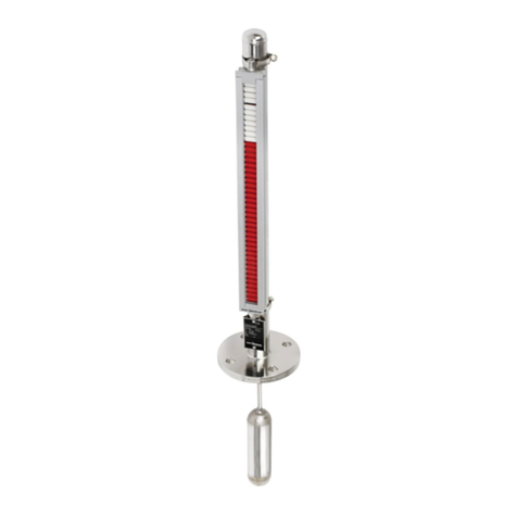
MicroScan is an ultrasonic, non-contact level measurement
device of mono-block construction (combing the sensor and
electronic components in a single unit). MicroScan provides
reliable and precise level measurement results of both liquids
and solids.
It can be used for the following measurement tasks:
)Liquid tanks with calm surfaces
)Solids tanks that are dust-free
MicroScan has a range of up to 5 m (16.5 ft) with an
accuracy of approx. 0.25% within that range.
MicroScan is available in two configurations:
)MicroScan with no display and no keyboard ("Blind" unit)
)MicroScan with optional display but without keyboard
The following models are available for each configuration:
)MicroScan L for liquids
)MicroScan S for solids

MicroScan User’s Manual
2
The following diagrams show the front and side views of
MicroScan, and its dimensions:
Figure 1: Front View of MicroScan Figure 2: Side View of MicroScan

Introducing MicroScan
CHAPTER 1
3
MicroScan Specifications
Accuracy 0.25%* of measuring range
Resolution 1 mm (0.04")
Beam angle 5°@ 3db point
Ambient temp’
compensation
Automatic
* 0.25% or 1.25cm whichever is greater.
Measuring Ranges
MicroScan L for liquids 0.25 m — 5 m
0.8 ft — 16.4 ft
MicroScan S for solids 0.25 m — 3.5 m
0.8 ft — 11.5 ft
Mechanical Specifications
Enclosure IP 65, mono-block construction.
Plastic enclosure: ABS+UV
Wetted parts Sensor body: PolyProp. PVDF, optional.
Stainless Steel for Liquid model; Coated
Aluminum for Solid/Liquid model.
Operating
temperature
-40°C to + 70°C
(-40°F to +158°F)
Mounting 2" BSP or 2" NPT

MicroScan User’s Manual
4
Mechanical fitting Conduit connection M20x2.5 or
1/2" NPT
Operating pressure Atmospheric
Dimensions 22.3 x 11 x 4.5cm (8.7 x 4.3x 1.7in)
Weight Approx. 0.75Kg (1.65lb)
Electrical Specifications
Optional Display LCD, four digits, seven segments
Operation Four push buttons
Loop current 4 — 20 mA, 750 Ω@ 28 VDC
Supply 12 — 28 VDC (CE certified)
Certificates CE — EMC
MSU Specifications
Display LCD (4 digits — 7 segments)
Keyboard 4 buttons
Cable 0.60m (23.6in)
Housing material ABS + UV
Dimensions 9.5X11X2.5cm (3.7X4.3X0.98 in)
Weight 0.25 Kg (0.55 lb)
Certifications CE

Introducing MicroScan
CHAPTER 1
5
Sensor Recommendations
Material Description
Stainless Steel For liquid applications.
High resistance in highly
acidic and alcoholic
environments.
Less sensitive to echoes (in
Solid applications).
Coated Aluminum Designed for complex
environments with
problematic echoes, such as
non-conductive vapors, solids
or liquids.
Good performance in
problematic applications.
High sensitivity to echoes.

MicroScan User’s Manual
6
Chapter 2
Installing MicroScan
Precautions
)Ensure that MicroScan is mounted in an area that meets the
stated temperature, pressure and technical specifications.
)Ensure that high-voltage sources or cables are at least 1 m away
from the sensor and its cable.
)Use a conduit connector that is either 1/2" NPT or M20x2.5
compatible (depending on the MicroScan model you have), to
ensure the unit remains sealed.
)Use 26-16 AWG round wires for the MicroScan’s electrical
connections.
)Ensure that cables are routed correctly and tightened along walls
or pipes.
)Installation and operation of this product should be performed,
according to the Product User Manual and Product Certification,
otherwise the use of this product is prohibited.

Installing MicroScan
CHAPTER 2
7
Installing MicroScan
When installing MicroScan, ensure that it is:
)Mounted above the dead-zone area.
NOTE:
If the device enters the blocking distance (dead
zone), it will not measure correctly.
)Positioned at least 0.5 m (1.64 ft) away
from the tank walls.
)Perpendicular to the surface of the
target.
NOTE:
Even the slightest difference in angle may affect
echo quality.

MicroScan User’s Manual
8
)Placed as far as possible from noisy
areas, such as a filling inlet.
Installing MicroScan on Threaded
Flange/Thread-Free Flange
MicroScan is available in two thread types, 2" BSP or 2" NPT.
MicroScan can be installed with threaded-flange mounting or
with thread-free flange mounting, as shown below:
Figure 3: Threaded Flange/Thread-Free Flange Mounting

Installing MicroScan
CHAPTER 2
9
NOTES:
When installing a thread-free flange mounted unit, you will need a 2"
locking nut to secure the unit inside the tank.
When installing a threaded flange, ensure that it matches the MicroScan
threads.
¾To install MicroScan:
1Insert the threaded end of MicroScan into the aperture at
the top of the tank or pipe.
2Bolt MicroScan into place in one of the following ways:
)Threaded-flange mounting: Screw the unit into a
flange with a threaded 2" hole.
)Thread-free mounting: Place MicroScan in the flange,
and bolt it from within the tank with a 2" locking nut.
NOTES:
Tighten the nut by hand only. When tightening the nut, hold the
sensor housing (refrain from holding the MicroScan unit when
tightening the nut).Make sure that the seal is leak proof.

MicroScan User’s Manual
10
Installing MicroScan via Extension
Pipes
If the level of the measured surface falls within the dead-zone
area, you should use an extension pipe to mount MicroScan.
When using an extension pipe, ensure that:
)The sensor is positioned in the center of
the pipe.
)The pipe extension is parallel to the
side/tank walls.
)The internal pipe diameter is at least 3"
wide.
When installing the MicroScan with extension pipes, follow
these specifications:
Pipe Length Internal Pipe Diameter
0.50 m (1.64 ft) 3"
1 m (3.28 ft) 3"
NOTE:
It is always recommended to use interference signal feature (Pr.03)
to locate interfering signals when using an extension pipe.
It is highly recommended that the extension pipes material would
be PVC or Plastic and not Stainless Steel.

Installing MicroScan
CHAPTER 2
11
Connecting the MicroScan to a Power Cable
1Unscrew the four Allen screws from the MicroScan front door.
2Detach the front door from the MicroScan unit.
3Remove the rubber sealing from the conduit entry.
4Thread the power cable through the conduit entry.
5Remove the plastic shell from the power cable.
6Connect the +24VDC wire to Terminal 1, connect the
0VDC (GND) wire to Terminal 2 on the wiring block.
7Make sure that the terminals’ screws are properly fastened.
8Attach the front door to the MicroScan unit.
9Screw the four Allen screws to the plastic door.
Figure 4: MicroScan Power Connections
NOTE:
Make sure that the O-Ring of the MicroScan's front door is properly
positioned to maintain the unit sealed.

MicroScan User’s Manual
12
Connecting the MicroScan to the MSU
(MicroScan Setup Unit)
The MSU is an hand held device which enables you to
configure the MicroScan unit according to your application
requirements, quickly and simply. Once the MicroScan unit
configuration is completed, the MSU can be utilized to
configure other MicroScan units.
The MSU should be connected to the MicroScan unit after
connecting the unit to a power supply.
1Remove the plastic cap from the MSU connector located
on the MicroScan unit (the cap is chained to the
MicroScan unit).
2Remove the plastic cover from the MSU multi-pin
connector.
3Attach the MSU male connector to the female connector
on the MicroScan unit, located on its left side panel.
4Make sure that the connectors are in the right position
and properly attached.
5Rotate the plastic clasp on the MSU connector, half way
to the right, to ensure the connectors are firmly closed.
Figure 4.1: MSU Communication Connector

Installing MicroScan
CHAPTER 2
13
Non-Intrinsically Safe Connections
Figure 5: Non-Intrinsically Safe Positive Ground Connection
Figure 6: Non-Intrinsically Safe Negative Ground Connection

MicroScan User’s Manual
14
Power Supply and Load Resistance Recommendations
The following table specifies the recommended resistance
range for each power supply voltage (Non-Intrinsically Safe).
Power Supply
Voltage
Minimum Current
on Resistor
Maximum Current
on Resistor
12 V 0 Ω50 Ω
15 V 0 Ω220 Ω
24 V 41 Ω610 Ω
28 V 68 Ω820 Ω
Ripple/Noise Parameters Recommended for
the Power Supply
The following ripple/noise parameters are recommended for
the power supply:
)For less than 15 V: 75 mV p-p max
)For more than 15 V: 100 mV p-p max
Table of contents
