SolidFocus TR800 User manual

Owners Manual
For safe use and product knowledge, please
completely read this Product OWNERS MANUAL.
TR800 / TR1000 / TR1200 / TR1200i
www.leisureconcepts.com.au

35
Console Overview
Treadmill Operations 31
Moving and Storage
Maintenance and Troubleshooting 37
TR800 / TR1000
TR1200 / TR1200i
2
3
15
20
23
this treadmill
To reduce the risk of electric shock, unplug the treadmill from the wall outlet when not in use,
before performing any maintenance, or before moving the treadmill.
Do not lean against or climb on the treadmill. Doing so may result in the treadmill tipping and
falling and could result in serious personal injury.
Do not hang or place items on the treadmill. Doing so could result in shifting the weight
balance of the treadmill causing it to tip over or fall causing serious personal injury.
Do not operate with the side rails removed.
Keep the treadmill on a solid surface, with the side rails and front a minimum of two feet from any
walls or furniture. Make sure that the area behind the treadmill remains completely clear during
use. A minimum of 1.5m of clearance is required for safety reasons.
Do not operate where aerosol spray products are being used or where oxygen is being administered.
Never place the power cord under carpeting or place any object on top of the cord, this may
Use this exercise product for its intended use as described in this Owner’s Manual.
Do not leave your treadmill running while not in use.
When in use children and pets should be kept at least 3m away.
treadmill at all times.
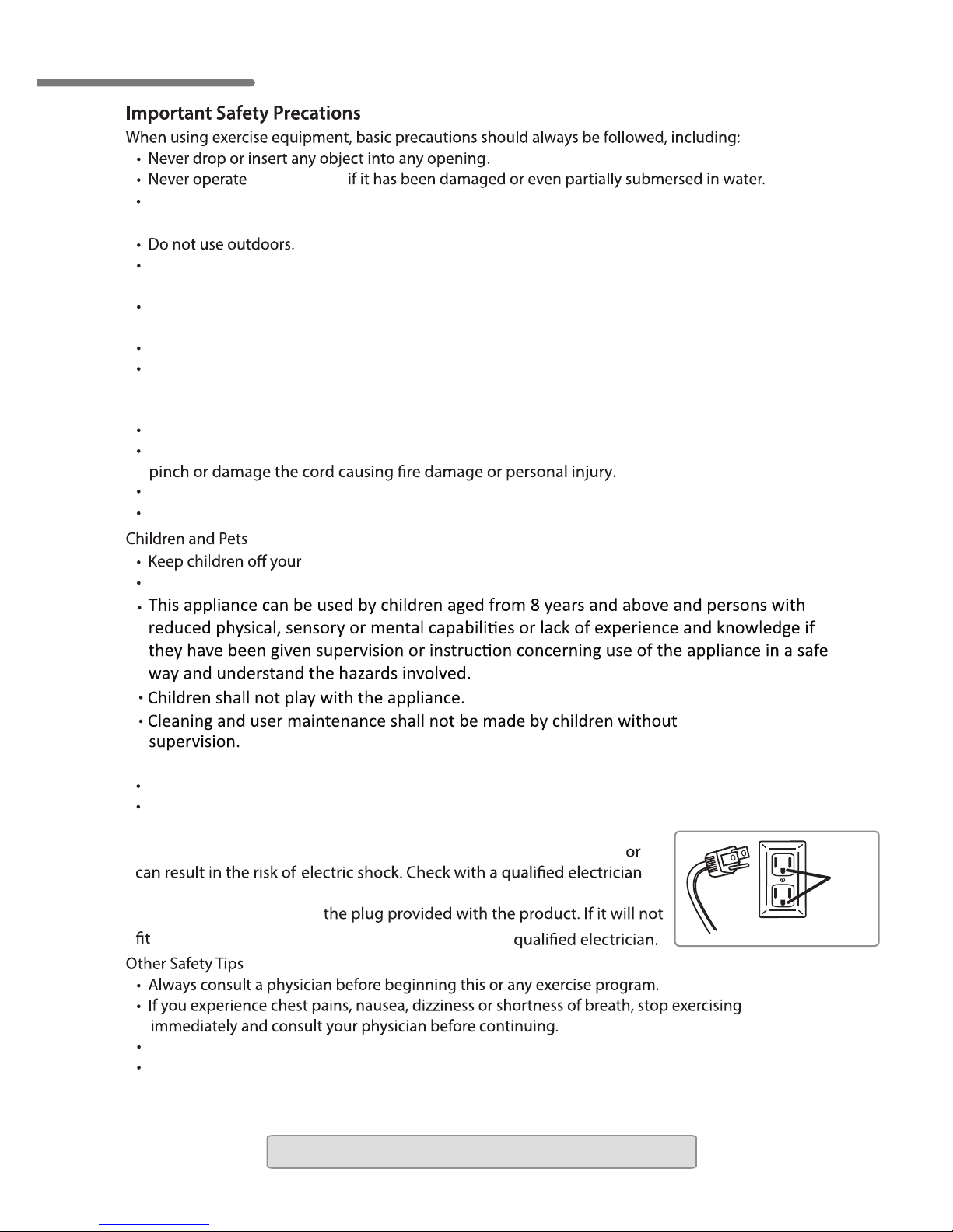
Grounding Instructions
Never use extension cords between the treadmill and the wall outlet.
This product has a grounding plug similar to the illustration below.
Never remove or otherwise bypass the eletrical ground terminal.
Gounded Wall Outlets
Treadmill
Plug
Gounded
Socket
Danger: Improper connection of the equipment grounding conduct
or service person if you are in doubt as to whether the product is properly
grounded. Do not modify
in the outlet, have the proper outlet installed by a
Note: Read all instructions and save for future use.
Do not wear clothing or jewelry that might catch on any part of the treadmill.
This treadmill is equipped with a safety key. If the key is removed from the display, the treadmill will
immediately stop. Always clip the cord that is attached to the safety key to a part of your clothing so
the key will be pulled from the display, stopping the treadmill, in case of an emergency.
Owners Manual
2

Treadmill We
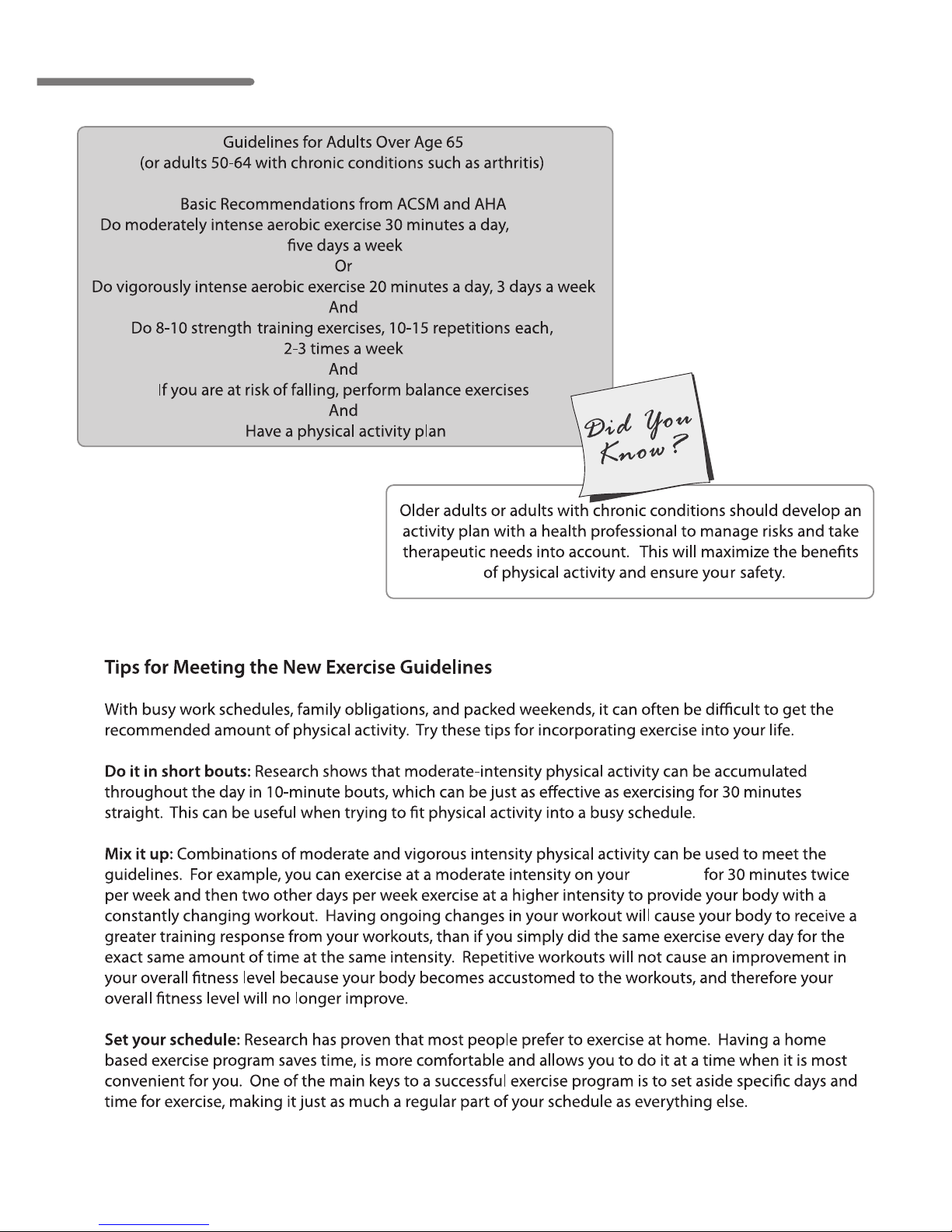
ACSM: American College of Sports Medicine.
AHA: American Heart Association.
USA.
3
TR800/ TR1000
TR1200 / TR1200i
Owners Manual
4
Treadmill
5
TR800/ TR1000
TR1200 / TR1200i
Owners Manual
6

7
TR800/ TR1000
TR1200 / TR1200i

Owners Manual
8

9
14 kgs
Our
TR800/ TR1000
TR1200 / TR1200i

Owners Manual
10
11
We’re
TR800/ TR1000
TR1200 / TR1200i

Owners Manual
12
Taking Americans for example:
13
TR800/ TR1000
TR1200 / TR1200i
Owners Manual
14

15
treadmill
1
13
10
6
5
7
9
14
25
4
11
2
3
15
8
12
Tools and Screws included in Hardware Bag
Wrench-17mm
Wrench-5mm
Wrench-6mm M4*10L (4 pcs)
M8*70L (2pcs)
Wrench-13mm
We
Item# description
1 Main Frame
2 Left handrail post
3 Right handrail post
4 Handrail
5 Console
6 Accessory Tray
7 Back cover
8 Console Bracket
9 Left handrail cover-outer
10 Right handrail cover-outer
11 Left handrail cover-inner
12 Right handrail cover-inner
13 Base cover-Left
14 Base cover-Right
1
25
5 S
Console housing
afety bar cover (TR1200)
(x2 on the TR800)
(x2 on the TR800)
TR800/ TR1000
TR1200 / TR1200i

Owners Manual
16
Step 2: Handlebar Support Post Assembly
A. Remove the screw (A) and nut (E) that are pre-assembled on the frame from each side of the
base using the 6 mm Allen wrench and 17 mm open end wrench provided in your tool kit.
These two screws will prevent the handlebars from rotating up into their upright position.
B. Stand the support posts and handlebars up into their operating position and re-attach the
.ylerucesnethgiT.A2petsnidevomer)E(stundna)A(swercs
C. Attach the left (13) and right (14) base covers using a Phillips screwdriver and 2 machine screws (G)
on each side. The 4 base cover attaching screws are located in the hardware bag.
13
G
A
E
Step 1: Unpacking Treadmill
A.
B.
Cut packaging straps and remove.
Remove the box top.
C. Remove small parts and packaging material and unwrap parts.
D.
Cut corners of the bottom box and remove all packaging material to begin assembly. The
treadmill can be assembled in the box. No need to pick the treadmill up to remove it from box.
Note: Make sure the wire harness coming from the front of the frame to the base of the right
handlebar support will not be pinched when pivoting the right handlebar support up
into position.

17
9C
B
10
blue rubber ring
X
8
TR800
12
*Note: the TR800 inside handlebar
cover is not pre-attached and
comes in two pieces.
Step 3: Handlebar Assembly
A. Rotate the handlebars down so they are positioned on top of the handlebar posts.
Secure the right and left handlebars to the support post using the 2 M8 x70L screws (B)
provided in the hardware bag
Note: Make sure that the wires on both sides are not pinched
in-between the handlebars and the handlebar post.
B. Rotate the console bracket (8) up in the back until it reaches its normal operating position.
C. Place the left outside handlebar cover (9) next to the inside handlebar cover (pre-attached).
allowing the plastic ridge to sit in the groove of the blue rubber ring. Secure these three
parts together using the self-tapping screws (C), which are pre-installed in the outer cover.
Repeat this process on the other side with the right outside handlebar cover (10).
sure there are no wires obstructing the bolt hole. Also, lightly pulling the handlebar
one way or the other will help line up the bolt holes.
TR800/ TR1000
TR1200 / TR1200i

Owners Manual
18
Step 4: Assemble Console Components
A. Attach the blue accessory trays (6) to the
bottom of the console housing using 8
self tapping sc
console housing (25).
rews (G). Preinstalled in
B. Attach the console (5) to the console
housing (25) using 6 screws (G). These
ehtfokcabehtnodellatsni-erperaswercs
and then reinstalled with the console in
place.
G
G
25 5
6
Step 5: Attach Console Assembly
A. Place the console assembly onto the
console housing frame mount (8) and
attach the assembly using the 7
screws (F), preinstalled in console
housing (25). Be sure not to pinch wire
harnesses during this step.
i. Main Harness: 5-pin and 7-pin
ii. Hand Pulse harness: 2-pin
iii. Speed Control Harness: 3-pin
(the wire colors need to be
matched.)
iv. Incline Control Harness: 3-pin
(the wire colors need to be
matched)
Note: Be careful to properly connect all wiring
connectors with their correct corresponding
wiring harness. Pay attention not to bend any
pins and make sure the connectors click in
place.
F
B. Connect all wire harnesses including:
C. Tuck extra wiring harness into the
opening behind the console.
8
(color doesn’t matter.)
Note: TR800 and TR1000 have 5-pin
Step 6: Attach the Back Cover Plate
A. Align the back console cover plate (7)
over the back of the console housing and
7
H
attach using the 4 screws (H), pre

19
Step 8: Cut red tie strap and roll out of box
Step 9: Plug the power cord in and turn the treadmill on
Step 10: Install safety key
Step 11: (TR1200i only) Set Time and Date
power receptacle
red tie strap
Step 8 Step 9
See Moving and Storage on page 32
safety key
To set your consoles time and date,
follow these steps:
1. Remove the safety key and re-install
2. Press any of the quick speed buttons for 3
seconds to initiate the date and time set up
mode.
3. Press the UP / DOWN buttons to set the correct
YEAR, Press Enter
4. Press the UP / DOWN buttons to select the
correct MONTH, Press Enter
5. Press the UP / DOWN buttons to select the
correct DAY, Press Enter
6. Press the UP / DOWN buttons to set the HOUR,
Press Enter
7. Press the UP / DOWN buttons to set the
MINUTES, Press Enter
USB - Port
Head
Phones
Mp3- IPod
comp ati bl e
Audi oCenter
I NTELLI - Guard
Automat icSafety pause
I NTELLI - Step
Count your steps
I NTELLI -Port
Transfer and trackyour
workout data
3. 0
MPH
4. 0
MPH
5. 0
MPH
6. 0
MPH
Feat ures
To St art
Press and hold START
but tonto t urn on
Press START to begi n
energy
Step 7: Lock Console Angle
thgithcnerwnellAmm5ehtgnisU.A
Securely Tighten
TR800 / TR1000
TR1200 / TR1200i
This manual suits for next models
3
Table of contents
Other SolidFocus Treadmill manuals


