Solidyne Audimax 362 HD User manual


Audimax 362HD

Table of contents
! "
#$
Chapter 1 Installaon.........................
%%"!!&'
%#!()"!'
%%#*)''
%+,(-(.
%/01232456.
%07(.
%%28
%015 8
%'/ ! 1 &9 5!!
!&118
%.!:;<
%.%!&!=0!&1!<
%.%%+,>!!!<
%.#)!<
%./1(!&!?
Chapter 2 Using the processor............9
%07 ?
1;?
%( ?
@A1%B
Chapter 3 Theory of audio processors 11
/%!>!C%%
/1/.2 ! "%
/%!1&5%
/,&:!%
//#@$D$%
%E:C!C@&!%
E((1!%/
/E (@!%/
E051@(!!%
'EC&FA!%
.E!C,1%
8E!@1!%'
07(!&%'
Chapter 4 – Technical Speci(caons. 16
Audimax 362HD /

About this manual
1CG!!! 1(!>
C !(!1&1H &(1 ! !I1 C
>! ! C C &!& ! && E
!"!(!
What’s in the box?
D1/.2(&:&1E
!
"
#$%&''
Overview
!1&!>C>"!&15E
•Audimax 362HD processors are designed for rack
montage in 19” standard racks. Also it can be used
on a table or desktop, uitting the lateral supports.
•The room temperature must be between 5 and
40°C (41°/104° F). Avoid the direct solar ray
incidence on the e uipment. Avoid the proximity of
heat sources and high electromagnetic fields (high
power transformers, motors, etc). 462-MKII have
internal protection against RF fields, that allows
assembly it next to AM/FM RF amplifiers.
•The installation in very humid places or with saline
atmosphere will have to be avoided, since they will
can cause corrosion in the printed circuit board and
electronic component.
WARNINGS
AC
Voltage
110/220 VAC.
!"
CHECK IF THE VOLTAGE SWITCH IS IN
THE CORRECT POSITION BEFORE TO
PLUG THE POWER COR .
!!!#!!
!"$ %!"
&'())*)&*+'$+"
,%!
-!!
%!%
.!"
/!/!!
!%-
%0,!"
Audimax 362HD

Chapter 1
Chapter 1
5
5
1.1 Power source A J@ K!>C&!!&(5>
@%B-B "&H&1!!
(D !5>@
! %BL !"H
A!>>&5
BJ!:
CJ$!>
DJD-M"&
1.2 Rear panel - wiring
Inputs and outputs are electronically balanced.
Use shielded twisted pair audio cables for audio
connections (microphone cable). Input and output
connectors are XLR. Connect as the following:
% $
3N6
/ 3)6
A 7#( N1,("!:
O!1O1H"(1&!%B
P
B +&1(&&!
1"!:">)%B1,K
C 7#&1(
1.2.1 RJ-4
D Balanced inputs are a ailable on an RJ45
connector.
Today many broadcasting mixers gi es inputs and
outputs on RJ45 for the analogical audio signals; and
are wired using CAT-5 shielded twisted pair (STP).
With the arri ing of audio o er IP (AoIP) se eral
companies start to use RJ-45 and multipair shielded
cable to replace to the different traditional audio
connectors, in order to standardize all in one type of
connector and cable.
In fixed installations, like radio stations, the use of
connectors RJ45 presents se eral ad antages
respect to the traditional connectors: a unique cable
is able to send both channels, reducing the quantity
of wires nee/ded. Additionally, installation is easy
and the tools needed are a ailable in any city, due
are the same used for data networks. And you don't
need to solder anymore!
There is no standard to connect an RJ45 with audio
signals; but Audimax 362HD are compatible with the
accessories manufactured by StudioHub (USA), a
brand widely used in radio stations. The following
table shows the pinout. of RJ45 inputs.
RJ45 PIN COLOR
1*2345
*2365
7345
8+$
9
:365
;6193!%5
<4193!%5
=>
+=>
&
&=>
+
&=>
&
Audimax 362HD '

At the end of the STP cable, the connection to the
audio de ice (microphones, speakers, audio players)
needs standard audio connectors.
The RJ45 wiring offers short end cable with female
RJ45 to any standard audio connector. Please refer
to web site for more info.
1.2.2 USB input/output
E Audimax 362HD /USB ha e an optional module
that enables to send and recei e from a computer ia
USB (USB A/B cable).
Connect the unit to any USB port of a computer
running Windows©. When connecting, Windows©
recognizes the USB de ice and install the dri ers.
Additional dri ers are not required. Audimax 362HD
will appear on Windows like one stereo USB audio
de ice and one stereo USB recording de ice.
To check the a ailable sound de ices, go to
“Windows Control Panel > Sound devices > Audio”.
Here the default sound de ices are defined.
ABOUT USB DETECTION
Before connecting the USB cable to the computer, make sure that
both the console and the computer have an effective ground by
power cords. For safety, connect a tester in the range of 25 AC
between the chassis of the PC and console and verify that the
voltage is zero. Only then connect the USB. If there are differences
of tension, the USB port on the console or the computer may result
damaged.
We recommend do not change the USB cable to other USB ports,
to avoid that Windows change the order of USB devices.
Windows 7 / 8.1,: Check that the audio recording device was
properly recognized. If Windows 7 recognized it as "microphone
device", the recordings will be mono (the same signal in both
channels). To correct this: Control Panel → Sound → Record →
choose the USB device (shown as USB microphone) and click
[Properties]. Then select the tab "Advanced", display the menu of
formatting options and choose a format for stereo recording (2
channels, 16 bits, 44100Hz).
1.3 Modo HD 32456
HD mode is suitable for audio applications where the
stage FM stereo coding is not used.
The main feature of "HD mode" is that the pre-
emphasis (75/50 microseconds) is disabled,
achie ing a brighter treble and rich sound. This
enables the processor to be used in sound
reinforcement installations (small rooms,
auditoriums) in popular music concerts, discos,
sound systems in malls, etc.
In HD mode, the processor connects using the audio
outputs (balanced or USB).
When the unit is set to HD mode:
•Pre-emphasis for FM is disabled (and therefore de-
emphasis on audio outputs is disabled).
•A fast limiter is enabled over the audio outputs.
•The MPX output turns o.
To change the working mode, you need to access to
internal micro-switches. For this, remo e the top
co er following the indications:
All switches 'ON' = FM
Mode
) ?@@? A ($
B
The FM/HD mode is
indicated by the LED
“FM” (ON = FM, OFF =
HD). By default the unit is
set for 'FM Mode'.
1.4 MPX Output
Audimax 362HD has dual MPX output, with
independent le el control. The secondary output
allows to connect a backup transmitter. Or a second
transmitter for nocturnal emission.
The connectors are a BNC. For MPX output use 75
ohms coaxial cable (standard in CCTV). The
maximum recommended length is 25 meters.
When use the MPX input of the transmitter, make
sure that the internal pre-emphasis stage is disabled
(flat response between 20 – 100 KHz).
Is ery important to ha e an appropriate ground
installation.
. Audimax 362HD

1.4.1 Humming
If some residual humming appears when the system
is started up; turn off the unit. If humming disappears,
check the 462 input connections. If the humming still
here; unplug the MPX cable. If humming ends, this
indicates that a problem occurs with the ground
connections.
Ne ertheless, this problem rarely can occur since the
Audimax MPX output is differential type, where the
BNC connector has floating GND to cancel possible
humming.
1.4.2 Modulaon level
The modulation depth is adjusted by changing the
MPX output le el. It is recommended to use a
program material with oice and loud music
(contemporary pop for instance).
•The le el of audio on the console must
peak at 0 VU, in order to the AGC stage
works in its point of equilibrium.
•Mo e all knobs to the center position.
•If the transmitter has modulation le el,
mo e to the minimun..
•Change the output le el of 362's MPX until
reach 75KHz of de iation (100%),
measurred at an FM Modulation Meter (like
Solidyne VA16) o using the instrument of
the tranmiter.
Some countries allows non-recurrent peaks at 110%
(I.e. FCC on USA). In daily use, the transmitter
needle-indicators can show modulation peaks higher
than 100%. This may be due to o ershoot or ballistic
responsi e a erage alues of sine wa e and the
indication is wrong with ery processed audio
material.
After adjusting the modulation le el, you can proceed
to customize the sound of the radio; adjusting 362HD
Audimax controls. Ob iously this does not affect
modulation adjustment, because the processor
deli ers a constant le el signal peak. To set the
personality of sound in air, proceed as described in
"2.2 - Audio settings".
1. .3 Diagrama de conexión a erra recomendado
Audimax 362HD 8

1.6 Work se<ngs
1.6.1 Processor as FM stereo coder
It's normal use as audio processor for FM. Audimax
362HD is located at the transmission plant,
connected as usual ia MPX transmitter. The second
MPX can be used to connect a backup transmitter.
The program signal input for analog inputs. Use the
appropriate input (balanced or unbalanced)
according to the characteristics of the console.
When the transmission station is far from the studio,
the processor is located at the transmitter site and
recei es PGM audio ia a point-to-point, which can
be: RF audio; digital audio ia optical fiber or UHF
(see the link Solidyne ADA102 STL).
1.6.1.1 USB for external streaming
Requires Solidyne Audimax 362 HD / USB. Using
USB is independent from MPX. This makes it
possible to use the same audio processing on-the-air
and on the webcast. The processor recei es the
program signal by the analog inputs, and outputs the
processed signal to USB and MPX. A computer
recei es the audio processing ia USB, for
streaming.
MPX is connected, as usual, to the FM transmitter;
while the USB is used to streaming, using a
computer, the processed audio.
It is recommended to install in the computer that
manages the streaming any remote access software.
Standard connection for FM with USB for streaming
1.6.2 Re-transmit an incoming stream
Requires Audimax 362 HD/USB and an external
computer. It is used, for example, to signal repeater
stations.
The external computer recei es streaming audio from
the main station (head station), either ia the Internet
or LAN. Decodes it and sends it as PCM signal to the
Audimax 362HD/USB processor through the USB
connection. The audio is processed and sent through
the MPX outputs to the FM transmitter.
The following diagram shows the signal flow for this
configuration.
We recommend installing any software on the remote
computer access to streaming encoder monitoring.
< Audimax 362HD

retransmission of a streaming
1.6.3 As audio processor
Audimax 362HD can be used in applications
requiring narrow the dynamic range of the signal,
or an increase in the sound; and do not in ol e FM
transmission (MPX disabled; see "1.3 HD mode").
Examples:
•Digital Radio Stations (HD Radio).
•Streaming
!
-! C
#
3 7 &- . !
!! # 5
"
•Pre-processing of audio in mobile units.
•Sound reinforcement for small shows;
rehearsal hall.
>),!($-
2!!!!D
! %
!"
#!!E"
•Rooms, auditoriums, conference rooms,
background music.
%)%+F
3)+F5%6 #!-
D
%-
%!
"
Chapter 2
Chapter 2
+(!&!
+(!&!
2.1 MPX level
The first adjustment is the modulation le el on the
transmitter (please see “1.4.2 – Modulation le el”).
2.2 Audio se<ngs
Audimax 362HD was designed to offers an easy
and ery intuiti e operation. You don’t need to ha e
specialized knowledge to start up the processor and
to adjust the sound settings. Simply begins placing
all knobs to the center position. That is all!
You will be on-air with a great sound. Soon you will
ha e to customise the sound according to the
musical style of your radio, for which we
recommends you to read the following explanations
kindly.
2.2.1 Input level
Audimax 362HD has an automated control for the
input le el. The rear panel presents balanced inputs
(+4dBu) and unbalanced inputs (-10 dBV). Make
sure to connect the mixing console to the appropriate
inputs according its nominal output le el.
Automatic input gain control (AGC) eliminates
ariations in characteristics of the operation of the
mixing console le el, and compensates for
differences in le el of the recorded material. That is,
Audimax 362HD ?

if the le el from the console remains ery low for
some time, the processor will compensate its input
to maintain a constant output le el.
If the output le el of the console exceeds constantly
0VU; AGC attenuate the signal. In this way the
program signal reaches the processing steps with
constant le el and sound on-the-air is consistent,
always with the same degree of processing.
D !>C( ((!(!H!
!$@H&1>!(
(! (!(!CE D 4! 3!6 1
"C (!& > & ! &Q
&1 3C"6 R 1 (: ! "C
D !1 3!16 1 ! !1
(!C
2.2.2 Customizing the sound
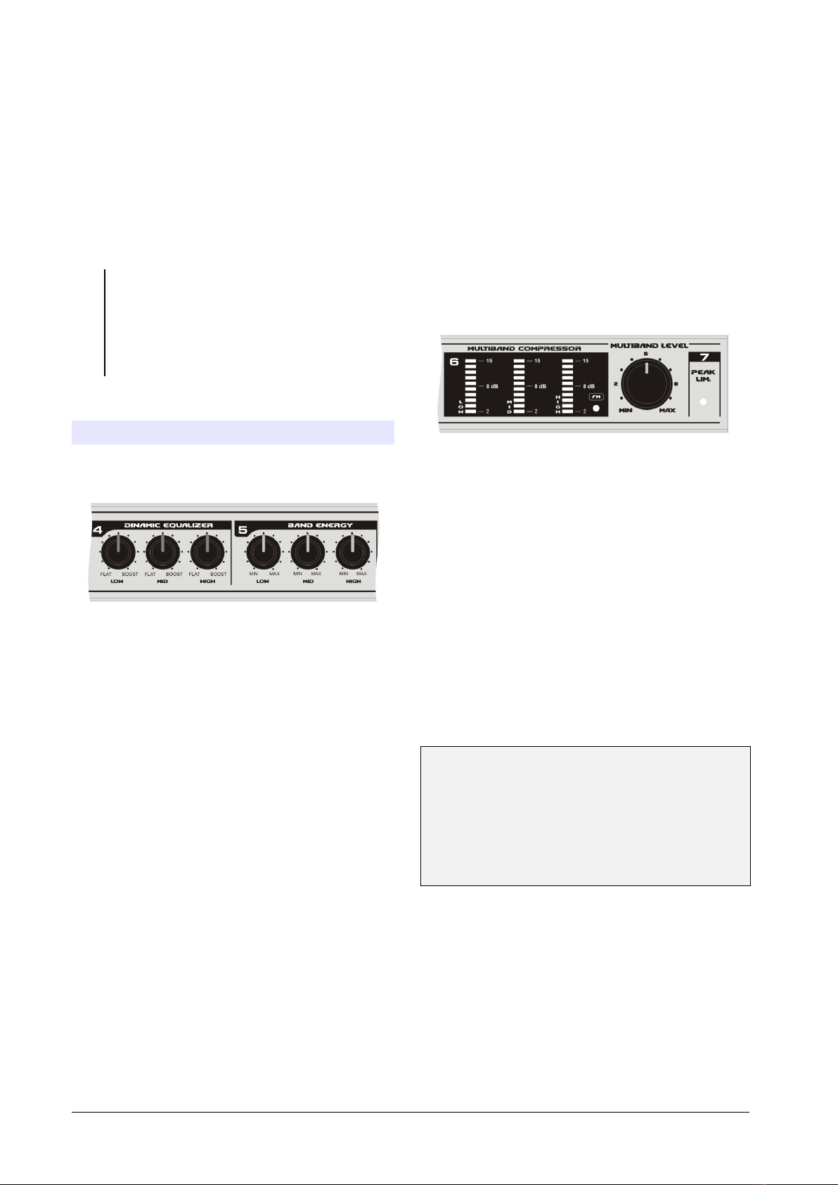
All adjustments are made from se en knobs located
in the front panel.
The stage Dynamic Equali er is a 3-bands
dynamic audio equalizer that allows reinforcing
certain frequencies, usually the bass, to ha e a
sound with ‘punch’, ideal for the car-stereos. Unlike
the con entional EQ’s, whose action is lost for high
le els of modulation, this EQ emphasizes its action
when higher is the modulation.
To adjust the dynamic EQ, make sure that the
multiband compressor is operating. For this, see the
LED’s meters located at the right; the first LED’s
must be illuminated.
In these conditions, turns the Dynamic Equalizer
knobs (Low, Mid and Hi). Turning the knobs to the
left, the response of the dynamic EQ will be flat.
Turning the knobs to the right, a boost in this band
takes place. When you boost a band, the action of
the compressor for this band increases.
NOTE: Dynamic Equalizer make changes o er the
attack times of mutiband compressor.
The Band Energy section increases the peaks
density for the band, achie ing high loudness
signals. This control changes the reco ery times of
the audio compressors. It must be settled according
to the musical style and the kind of sound that
you’re looking on-the-air: compact with high
loudness and “punch'’, turning the knobs to the right
(fast reco ery times); or more soft and smoothly,
with the knobs at the left (slow reco ery times).
Multiband Compressor is the core of the
processing system, constituted by 3 independent
audio compressors that works on 3 frequency
bands: Low, Mid and Highs.
The Multiband control changes the input gain of
the compressors. This control affects more
radically the output le el of the Audimax 362HD.
Turning this knob to the left you will obtain a
smoother sound, with little processing and therefore
with less energy. Turning it to the right, you will
increase the processing and the energy of the
sound.
Take in mind that with an excessi e processing you
will obtain a ery hard sound on the air, with high
energy, but too compressed (smaller dynamic
range) and with less definition (more clipping).
Normally a suitable le el is obtained when the
indicators LED’s of the multiband compressor act
without light the red LED.
Very important note: ( % ) *+
,*)-.)%%/'
!0%).'%12*
' %. / '3. % ( %
!.%%
-%.%)%/'
%B Audimax 362HD

Chapter 3
Chapter 3
D!C>1(!&!
D!C>1(!&!
NOTE: %)%'4
&5*,!!!)(
% *67/%!/
( % 0%
% )8 %! %
%&%96
3.1 A brief story...
From mid of the 1930 decade, when appears the
first compressors and expanders units, to the
present time, all chains of audio for broadcasting
incorporate de ices whose function is to alter the
dynamic range of the sound. The ad ance of the
technology impro es these de ices during the ‘70s.
The compressors, expanders and audio limiters
were gaining in efficiency and complexity. In the
beginning, its main parameters (attack and reco ery
times, thresholds, etc.) were fixed by design or by
the operator, through the de ice’s controls. In the
'70s, these functions begin to be automatic, based
on the characteristics of the audio signal, but ha ing
at the same time a control on their action to be able
to customize the sound.
When fi e or more de ices are grouped in a same
equipment, they begin to be denominated: AUDIO
PROCESSORS.
Since 1970, Solidyne introduces important
ad ances in this field, like the in ention of a control
technique based on FET’s with guided gate (see
publication in Re . Tel. Electrónica, September/70).
They follow di erse publications, ha ing particular
international rele ance the work published in
June/76 at the Journal of the Audio Engineering
Society, New York, U.S.A. where a new concept
was introduced, which persist to the present time:
PHSICOACUSTIC PROCESSING.
This new technique is the base for all the modern
audio processors for broadcasting use. The
necessity to process the phase to make
symmetrical the human oice wa eform is another
one of the techniques that Solidyne has introduced
internationally (see mentioned article AES). Today,
Orban, Omnia, Aphex, etc use our ideas.
The concept of psychoacoustic processing is simple
in essence, although of complex accomplishment.
It consists of analyzing the way in which the sound
is percei ed by our ear, considering di erse
in estigations and de eloped acoustic models.
The brain uses to process audio data, the
information that arri es through 30,000 ner ous
fibers, originating at the Basilar membrane. Then, it
will be possible to be computed the auditory
reactions and to be go erned all the aspects of the
audio processing. This way, the electronic system
works transforming the original signal into another
one, of greater energy and greater quality of sound.
Then, it will be possible to reduce the dynamic
range of the audio signals, to eliminate the peaks,
and e en, to clip them partially to increase its
energy.
If this were made directly, obeying to purely
electronic concepts of efficiency, the quality would
be degraded and the sound would be ery poor. If,
howe er, the psycho acoustic concepts are applied,
and factors like the aural masking, the pre and post
pulse inhibitions, the Hass effect, the reflections at
the ear pinna, the aural models of Dr Karjalainen,
etc; it will be possible to create a new generation of
processors that allow to important increases of
energy, increasing at the same time the sensation
of “Percei ed Sound Quality”.
At the light of these disco eries the
psychoacoustics processing was defined in these
terms:
PHSYCO ACOÚSTIC PROCESSING is the technique
that allows to increase the range of A or stereo
F transmission, by increasing the energy of the
audio signal, and also increasing the “quality of
sound” perceived by the listener.
Ne ertheless, it is fundamental throughout this
process, to maintain ery low the audio distortion
produced by harmonic and IM components. This
happens because the psychoacoustic processing
MODIFIES the wa eform of the complex signal of
audio, but IT DOES NOT DISTORT IT. Since the
distortion concept, in this context, implies the
existence of a sound that offends the ear, sounding
unnatural.
This is because the psychoacoustic processing
obtains that the ear accepts like of better quality
than the original one, to certain modifications of the
wa eform. But it does not mean an "anesthesia" to
the ear, to a oid percei ing the distortions due to
deficiencies in the quality of the electronic circuits of
the processors.
Considering that to obtain an excellent processing
is necessary, at the moment, to use between 7 and
10 stages of processors, the distortion of each
stage must be smaller than 0.01%. Greater
distortion alues, will lead inexorably to a
degradation of the sound quality. You must
remember that has been demonstrated (Journal of
AES, Vol. 29,4,p.243), that is possible to measure
distortions of 0.05% through a common
loudspeaker (distortion bigger than 3%). This
demonstrates that one distortion do not mask
another one. A practical rule is, then:
ALL DISTORTION INTRODUCED IN THE AUDIO
CHAIN OF THE TRANSMITTER, THAT EXCEEDS
Audimax 362HD %%

0.05%, COULD BE LISTENED BY THE AUDIENCE,
EVEN THROUGH RECEIVERS THAT HAVE VALUES
OF DISTORSION 50 TIMES GREATER.
This, of course, is not a no elty for the conscious
audio engineers around the World.
Therefore, the line of SOLIDYNE processors has
distortion alues smaller than 0,02%.
Few controls, easy adjustment...
The psychoacoustic processors created by
Solidyne, ha e 70% of their functions automatically
fit, under the control of the audio program. But they
also present the essential controls for customize the
sound of the radio, that you can adjust.
Audimax 362HD has a great ad antage: it does not
ha e critical adjustments. This means that in any
position of his controls always it sounds well. The
adjustment can be made then by inexpert people.
Simply taking all the controls to the center position,
you ha e an excellent sound on the air. From there
customize the sound so that the radio sounds as
you desired (this it is a question of personal taste).
3.2 Audimax 362HD overview
3.2.1 Introducon
The Audimax 362HD has 7 processing stages and
the stereo coder. Its main characteristic is the ease
of use, because it doesn’t require a specialized
technician to start up and to adjust the unit; and
neither it has the critical “Input le el” control, since
an automatic system adapts the input gain to the
output le el of any audio console, a oiding the more
frequent operational errors. His low cost is
appropriate for low-power FM radios, as well for
recording studio of high power radio stations. The
362-IT model is an excellent processor for
WEBcasting (radio on Internet).
Operating in a FM radio, the Audimax 362HD
increases the reach of the transmission,
impro ing the co ered area between 30 and 50%,
obtaining an impressi e audio quality that will
distinguish your radio station. The AudiMax sound
is smooth and warmth, with the classic
characteristics of the analogical processes of high
technology.
Audimax 362HD works with 3 bands and it’s fully
controlled by VCA (Voltage Controlled Amplifiers).
The stereo coder stage uses digital synthesis with
16X o ersampling, a technology de eloped by
Solidyne that guarantees ultra-low distortion and
high channel’s separation, not requiring any
readjustment during all its life utility. MPX output is
differential type, cancelling the residual humming.
3.2.2 Blocks Diagram
3.2.3 PROCESSING STAGES
Stage 1: Peak Asymmetry Canceller
:" HC (!5&!C1(5 >
&&!1H!
! ! C!& !! ( D
!& 54!1(>!H
& 1H 1 1>C
!&&!&!5&> &
(:"!115!CC!&
% Audimax 362HD

This creates an important reduction of the energy of
the audio signal, particularly when it pass through a
compressor, because the compressor sets its
compression le el for the greater peak, does not
concern its polarity. In this way, when a polarity is
fit to the 100%, the opposite polarity hardly
surpasses 50%, due to the asymmetry. The fact
that the music sounds louder than the human oice,
after pass through a compressor is a phenomenon
well known. This is because the musical sounds
are symmetrical, whereas the human oice is not.
In order to correct this problem, WITHOUT
INTRODUCING ANY ALTERATION AT THE
SOUND QUALITY, peak asymmetry canceller is
used.
This technique, based in a disco ery of the Dr
Leonard Kahn, acquires international alidity with
the work of Oscar Bonello, published at the Journal
of AES, Vol.24,5 in which it is described, for the first
time, the theory of its operation.
The peak asymmetry canceller is in essence an all-
pass network, a class of not minimum phase
network. That is: a network whose transference
function has zeros in the right semi plane. This
network has a full flat response to frequency; only
its phase response is function of the frequency.
This phase rotation, which must compliment ery
particular conditions, is responsible of the peak
symmetry of the audio signals. Signals that by their
nature are symmetrical (like most of the musical
instruments), are not modified by this processor.
This processor, by itself, allows to increase
between 3 and 5 dB the final power broadcast by
your transmitter (it is to say that it increases by a
factor of TWO the a erage power transmitted).
Numerous tests ha e been made in different
countries, to erify, in real conditions, these results.
Stage 2: Input Expander
The expander, pre ious to the compression
process, is an excellent resource to increase the
signal/noise ratio of the original program. This is
ad isable, since the compression process, when
reducing the high le el passages, consequently
increases the relati e le el of the passages of low
le el, and therefore the noise. This is a forced
consequence of the compression process that has
particular effect in the increasing of the ambient
noise of the microphones. To a oid this, Solidyne
processors incorporate a linear expander, pre ious
to the compressor stage.
The concept of linear expander implies an expander
that works within a ery wide range of signals,
below a threshold alue. That means it always
expands within that range, for any le el of signal.
That is to say that their cur e of transference,
based on the input le el, is a straight line (from
there the "linear" name). This implies that by each
10 dB that the input le el reduces, the expander will
reduce, for example, 13 dB. This happens for any
input alue, below the threshold. Then if the input is
reduced in 30 dB, the output will do it in 39 dB; that
is to say that the background noise has been
reduced in 9 dB. This way, the expander
compensates the increase of the noise that the
compressor, like undesired effect, will increase.
At this point, maybe you will be thinking that DOES
NOT HAVE SENSE to make an expander of the
signal and soon to compress it. You will think,
perhaps, that an effect cancels to the other. But it’s
not true for two reasons. First: the different attack
and reco ery times. Second: multiband
compressors ha e ele ated threshold, whereas the
linear expander has a ery low threshold and a
linear beha ior below the threshold. It means that
the actions do not cancel, because both processes
are not complementary.
The linear expander, to optimize its beha ior, has
instantaneous attack and a fast reco ery times.
Here is where the psychoacoustic concept “post-
pulse hearing inhibition” is used. This allows using
an expander with a quick reco ery time, so that the
ear does not percei e it. The broadband
compressor that follows the expander has a ery
slow reco ery time. Therefore, with impulsi e
signals, as the audio program, does not exist any
cancellation effect.
Another ad antage of using a linear expander
pre ious to the processing is that an excellent
audible sensation of dynamic range is obtained. In
fact, recent studies ha e demonstrated that the
audible sensation produced by the le el ariations
of an audio signal, is related to the changes
happened in the first 50 milliseconds, and is little
dependent of the reached final alue. This implies
that an expander in the short term is percei ed like
a great dynamic range, whereas the power
sensation (and e en the co erage area of the radio
transmitter) is related to the a erage energy, which
depends of the compression of the energy le el.
You can see that they are two concepts different.
With audio processors of con entional design, the
expander and the compression were antagonistic
concepts. This does not happen in the field of the
psychoacoustics processors.
Stage 3: Level Input Control
The Audimax 362HDHD has an automatic control
for the input gain. Manual adjustments are not
necessary. The AGC (Automatic Gain Control)
guarantee that the audio signal enters to the
delicate multiband compressors always with the
same le el, a oiding ariations on the transmitted
signal.
Audimax 362HD %/

The AGC is designed to work with input le els from
–10 dBu to +15 dBu, which qualifies to the AudiMax
to work with all types of audio consoles, from DJ’s
mixers to professional broadcasting consoles!
Stage 4: Mulband Compressors
The purpose of the multiband compressors is to
increase the percei ed loudness sensation. The
human oice and music will sound more solid, with
better dynamic balance. Still more, the increase of
the a erage energy of the audio signal is ery
considerable, increasing the co erage area of the
radio for A.M. and FM transmissions (for more info
isit www.solidynepro.com).
Multiband technology bases on the studies of
Ste ens (ref 1.2.3) about the loudness of each band
frequency and the studies of Zwicker (ref 4) about
its relation with the Critics Bands of the human ear.
The integration time of the ear to reach the
maximum loudness is of the order of 200
milliseconds (ref 5). This time must carefully be
incorporated to the controls of the loudness
compressors, to obtain the desired effect. The ear
will percei e a greater loudness when the band
compressors increase the relati e loudness le el.
The processor Orion 462 has frequency splitters
with Butterworth filters of 18 dB/octa e that di ides
the program signal in four frequency bands: low,
low-middle, high-middle, high. In this form, the
multiband compressor in independent form
processes each bank of frequencies. This way is
possible:
1. To increase the total energy, by the use of fast
compressors for bass and ultra-fast for treble. If the
bands were not di ided, the compressors with so fast
reco ery time would produce a disagreeable sound
effect; the percussion of low frequencies would
modulate the high notes. And the high notes of an
instrument would as well modulate the low tones, of
ioloncello, for example.
2. To increase the perceived loudness. This is
because most of the modulation capacity of a
transmitter is generally de oted to low frequency
signals, of less than 160 Hertz. Ne ertheless this
information contributes ery little to the loudness
sensation, due to the reduced sensiti ity of the ear
for those frequencies. Therefore is desirable to
increase the le el of the medium and high
frequencies. But this cannot be obtained by simple
equalizing, because the sound balance would be
destroyed. On the other hand, the peaks of high
frequency would saturate the transmitter. The
compression in separated bands allows increasing
between 6 and 12 dB the energy for high
frequencies without altering the tone balance; in
fact, the frequency response continues being flat.
3. To improve the audio quality. Processing
completely eliminate the "flat sound" sensation,
percei ed when a sonorous material is
compressed, by means of fast compressors. This
is obtained, additionally to the di ision in bands,
using attack times appreciably ele ated. This
allows that ery short peaks of the audio signal
arri e freely to the following processor (peak
clipper), that eliminates them, but maintaining the
psychoacoustic sensation of power associated with
the audio peaks.
Stage : Dynamic Equalizer
The Dynamic EQ is a 3 bands audio equalizer that
acts o er the threshold of the multiband
compressor.
This technology operates in 3 bands (low, middle
and high) modifying the density of energy (instead
the le el) of each band. Is formed by
complementary filters of 18dB/octa e carefully
designed to obtain flat response. This built-in
equalizer offers an enormous flexibility. In example:
is well-known that the use of EQ at the console
output has an ad erse effect in the sound quality,
since the more a frequency band is emphasized,
grater is the action of the audio compressor
(pre ious to the transmitter) for that band. Equalize
a band implies to unbalance the entire audio
spectrum. It doesn’t happen with DENSITY EQ,
since its action is coordinated with the following
stages. The boosting of a frequency band is
translated then in a correlati e modification of the
multiband compressor threshold, to carry out the
new equalization.
In this form, its action extends to the range of
sounds of ery high intensity, where the
con entional EQ’s are inefficient, due the excessi e
compression.
Stage 6: Energy Bands
Band Energy controls increase the peak density of
the audio bands, obtaining signals with ery high
loudness. Knobs act on the reco ery times of the
compressors. Each band ha e a different reco ery
time, of ariable range.
"Energy Bands" adjusts according to the music’s
style that the radio manages. Turning the controls to
the left you will ha e a smooth sound (long reco ery
times); whereas turning them to the right you
increases the energy for the bands, which will
produce a more “hard" sound with great "punch"
and "sharp" highs (fast reco ery times). As example
we say that for melodic music, classic (academic),
etc., in which there is no noticeable rhythmical
support, agrees not to emphasize too much the
Energy Band controls, that is to say, to use long
reco ery times. For Rock & Pop is ad isable to
increase the energy bands so that the sound has
more "punch".
% Audimax 362HD

Stage 7: Stereo Coder
The sum of the signals is sent to the stereo coder.
It uses digital technology to generate the MPX
signal. This technique, created by Solidyne, allows
to obtain a perfect coder with distortion 10 times
below the audibility threshold and channel
separation better than 75 dB.
It’s based on the o ersampling concept, that di ides
the audio signal in 16 samples that are processed
separately at 38 x 16 = 608 KHz. Due to this
ele ated sampling rate, the anti-alias filters works
o er 500 KHz, eliminating the “phase rotation” effect
at 53 KHz. With this new solution and the use of
ad anced technology in each part of the circuit,
residual components of distortion below -90 dB are
obtained.
It is described separately in this manual, the way to
do measurements and reception tests of the stereo
coder (see Chapter 4).
MPX processing
The studies about the modulation on an FM
transmitter indicate that when the transmitter is
modulated by stereo MPX signal appears a new
effect, not present on the original audio signal.
This effect, denominated in U.S.A. MPX
Interleaving (also known as peak correlation),
determines that the modulation peak in MPX does
not coincide with the modulation peak of the stereo
signal, considered in independent form.
This means, in simple terms, that if the peaks of
channels L and R are limited separately so that
MPX signal ne er o er modulate, during most of the
time, the modulation capacity of the transmitter will
be wasted. And this happens because signal MPX
is the sum of L+R but also includes the 38 KHz sub-
carrier. According to the relation of phase between
these three elements, there will be different peak
alues for the interlea ing. This phenomenon
indicates that is possible to increase the modulation
without increasing the de iation of 75 KHz of the
transmission, taking ad antage of the modulation
capacity that normally is wasted.
Audimax 362HD processor uses a MPX Processing
technology named Super Modulation. This
processing consists on a system that controls the
peaks, operating at 608 Khz, eliminating the peaks
in MPX base band signal and filtering them so that
there are not left residual components.
REFERENCES
1.- HD!>1H*!HK8H
(<%'
2.- H D 1!& 55 > !C 1)
1Q!&*C&.?H%)'H%?'.
3.- H@&!>!>1>&5Q
*!HK?H(.B/).B.H%?'8
4.- S"&:! J =I!( J Q &!5& 1"1 1
5H*!HK?H('<)''8H%?'8
.- C$>1H2!H(/?H11C0::!H!:H
%??B
6.- &! , 0#K0D + $
#@$*!>1!&CHKT
'+H%?8.
7.- &! , @ @D# @2@+D@ +
#@#H?1@ 5H,!0!&%??/
8.- &! ,H ,! 0: 3&! (! #U>6
1 @! !!& 1 &V5&H 01!1H
&!BBB
9.- &!,H 0511 !&1R&
@ !!>=0!D!H*!>1
!&CH"!:H0!&BB8
Audimax 362HD %'

Chapter 4
Chapter 4
J
JD&&(&4&5
D&&(&4&5
Input
XLR3 connector, self-adjusted le el
Le el: -10 dBu to + 15 dBu
Z= 600 / 10 Kohms, balanced
Output
Balanced, + 4 dBu Z= 600 / 10 Kohms, with de-emphasis
MPX Output
600/10 Kohms, factory set le el to
standard 4 Vpp. Differential output to cancel hum loops between
transmitter and studio ground
Frequency Response
20 - 16.000 Hz +/- 0,5 dB
measured below compression & limiter threshold
Harmonic Distortion
Below 0,02 % @ 30-15.000 Hz
Noise
Below - 90 dBA ref 100 % modulation
Stereo Separation
> 75 dBA
Subsonic Filter
Chebyshe 2nd order, 15 Hz
Asymmetry Cancelling
5:1 cancelling effect, using Khann-Bonello method
Expander
10:1 slope, 100 uS attack time
AGC (wideband)
VCA controlled, 30 dB range
Multiband Compressors
3 bands, 18 dB/octa e, linear phase crosso er
Compressors: 30 dB full range, 5:1 slope Automatic attack time / Release
controlled by Energy panel controls
IM Cancelled Clipper
IM attenuation > 30 dB below 250 Hz
Dynamic EQ
0 - 12 dB dynamic boost at Low, Mid and High Frequency
Processing Power
7 stages of processing de ices
Power
115 V / 230 V (rear switch selected)
50/60 Hz, 20 W
Dimensions
19" rack mount. Module one (44,4 mm)
Pilot tone stability
+/- 0,002 % (+/- 0,5 Hz)
STEREO CODER SPECIFICATIONS
Measured from internal Stereo coder
jumper to MPX out
Audio input
2 Vpp for 100 % MPX output (4 Vpp)
Frequency Response
15 Khz/5 order elliptic LP filter
20-15.000 +/- 1 dB
Attenuation at 19 Khz > 50 dB
Harmonic Distortion
Less than 0,01 % THD at 1 Khz
Below 0,015 % 20-10.000 Hz
Signal to Noise Ratio
Better than 85 dBA with reference to
100% modulation
Stereo Separation
Better than 50 dB @ 20-10.000 Hz
Typical > 60 dB at 1 Khz
38, 57, 76 & 95 KHz suppression
Below - 70 dB
%. Audimax 362HD
Table of contents
Other Solidyne Recording Equipment manuals