Solight V15 User manual
EN Digital Multimeter SOLIGHT V15
Thank you for purchasing this product.
Before using it for the first time, read this
manual carefully. Otherwise, you risk
danger to your health and damage to your
device.
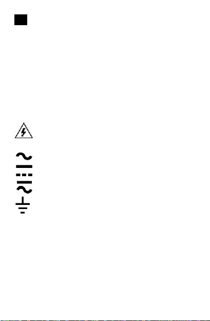
Important symbols
Warning! High voltage (danger of
accident)
(AC) alternating current
(DC) direct current
either DC or AC
earthing
Important safety instructions
A fundamental safety precaution when
using this device is to reduce the risk of fire,
electric shock and personal injury.
Therefore, make sure to observe the
following instructions:

1. Never use this device for any other
purpose or in any way other than that
described in the present manual,
otherwise the protection provided by
the device may be impaired.
2. Your finger or any other part of your
body must not touch the measuring
probes. Do not carry out
measurements with wet hands.
3. Use additional protective equipment if
you measure in areas of danger to life
and health.
4. Do not use the device if its body or
measuring probes are damaged. Do
not use in humid environment.
5. Before each measurement, check the
function of the main switch and make
sure it is set correctly.
6. When making a current measurement,
make sure the circuit is not live so that
you can connect the measuring
probes.
7. Do not carry out resistance and diode
measurements or circuit continuity
testing on a live circuit.
8. Do not exceed the selected range of
measured values on the rotary switch.

9. Take extra care when measuring live
on a circuit above 60V DC (direct
voltage) or 30V AC (alternating
voltage).
10. If a battery symbol appears on the
display, replace the battery to prevent
poor measurement results.
11. Use the device only indoor at
altitudes up to 2000m, temperatures
between 0°C and +40°C. Maximum
permitted humidity up to 40°C is 80%.
General specifications
•Display: LCD with maximum display
value 1999.
•Manual range adjustment
•Automatic negative polarity indication.
•Display zero setting: automatic
•Range excess indication: "1" or "-1"
•Indication of low battery voltage by
symbol
•Safety standards: CE EMC/LVD, CAT
II 600V, CAT III 250V, IEC1010
double insulation. Degree of pollution
2, overvoltage category II.

•Storage conditions: -10°C to -50°C,
humidity up to 85%
•Fuse: F 0.5A / 600V, 5 x 20mm
•Power supply: 2x AAA 1,5V alkaline
batteries
•Dimensions: W: 29 x L: 70 x H:
125mm, weight: approx. 128g incl.
batteries
•Sound signalization
Electrical specifications
Measurement accuracy is provided based
on the following formula: ±[(% of range) +
(last digit of the measurement)] at a
temperature of 23 ± 5°C and humidity of ≤
75%.

Direct voltage
Scope
Resolution
Accuracy
200mV
0.1mV
± (0.5% + 3
digits)
2000mV
1mV
± (0.8% + 5
digits)
20V
10mV
200V
100mV
600V
1V
± (1.0% + 5
digits)
Overload protection: 230V rms AC for
200mV range; 600V rms or 600V DC for
other ranges.
Alternating voltage
Scope
Resolution
Accuracy
200V
100mV
± 2% + 10
digit
600V
1V
Frequency range: 45 – 450Hz
Overload protection: AC or DC 600V rms.
Indication: Average value (rms or sine
wave)

Direct current
Scope
Resolution
Accuracy
2000μA
1μA
±1.8% + 2
digits
20mA
10μA
200mA
100μA
±2.0% + 2
digits
10A
10mA
±2.0% + 1
digits
Overload protection: fuse 0.5A/600V,
F10A/600V
Note: 10A within 10 seconds

Resistance
Scope
Resolution
Accuracy
200Ω
0,1Ω
± 1.0% + 10
digit
2000Ω
1Ω
±1.0% + 4
digits
20kΩ
10Ω
200kΩ
100Ω
2000kΩ
1kΩ
±1.0% + 4
digits
Maximum circuit voltage: 3V. Overload
protection: 15s max. 230V rms.
Diode and circuit continuity test
Icon
Description
Measuring
conditions
The display
shows the
approximate
value of the
diode cut-off
voltage
Current in reverse
direction - direct
current approx.
10μA.
Built-in buzzer
sounds when the
electric
resistance is less
than 50Ω
Circuit voltage
approx. 1.8V
Overload protection: 15s max. 230V rms.

Operating manual
Direct voltage measurement
1. Connect the red test lead to the
"VΩmA" socket, then the black lead to
the "COM” socket
2. Set the switch to the appropriate "DC
V" range. If you don’t know the
measured voltage, select the highest
range and gradually reduce it until
readability is reached.
3. Connect the test leads in parallel with
the measured circuit.
4. Read the displayed voltage from the
LCD including voltage polarity.
Note:
•Values "1" or "-1” on the display
indicate exceeded measuring range.
Choose higher measuring range.
•Do not measure circuits with a voltage
expected to be higher than 600V AC
or DC rms as this would damage the
multimeter electronics.
•Use extreme caution when measuring
high voltages

Alternating voltage measurement
1. Connect the red test lead to the
"VΩmA" socket, then the black lead
to the "COM” socket
2. Set the switch to the appropriate "AC
V" range.
3. Connect the test leads in parallel with
the measured circuit.
4. Read the indicated voltage and polarity
from the LCD.
Note: The same notes as in "Direct voltage
measurement” above apply
Direct voltage measurement
1. Connect the black lead to the “COM”
socket. When measuring current up to
200mA, connect the red lead to the
"VΩmA" socket. To measure currents
from 200mA to 10A, connect the red
lead to the "10A" socket.
2. Set the switch to the appropriate "DC
A" range. If you don’t know the
measured current, select the highest

range and gradually reduce it until
readability is reached.
3. Connect the test leads in series with
the measured circuit.
4. Read the measured current on the
display.
Note:
•Values "1” or "-1” on the display
indicate exceeded measuring range.
Choose higher measuring range.
•The maximum input current is 500mA
or 10A depending on what socket the
measuring lead is connected to. A
0.5A/600V fuse protects the circuit
measuring currents from 200mA to
10A. When measuring 10A, do not
exceed the measuring time of 10
seconds.
Resistance measurement
1. Connect the red test lead to the
"VΩmA" socket, then the black lead to
the "COM” socket
2. Set the switch to the appropriate "Ω"
range.
Popular Multimeter manuals by other brands


Gossen MetraWatt
Gossen MetraWatt METRAmax 6 operating instructions

PeakTech
PeakTech 4000 Procedure of calibration

YOKOGAWA
YOKOGAWA 90050B user manual

Gossen MetraWatt
Gossen MetraWatt METRALINE DMM16 operating instructions

Fluke
Fluke 8846A Programmer's manual

Tempo Communications
Tempo Communications MM200 instruction manual


