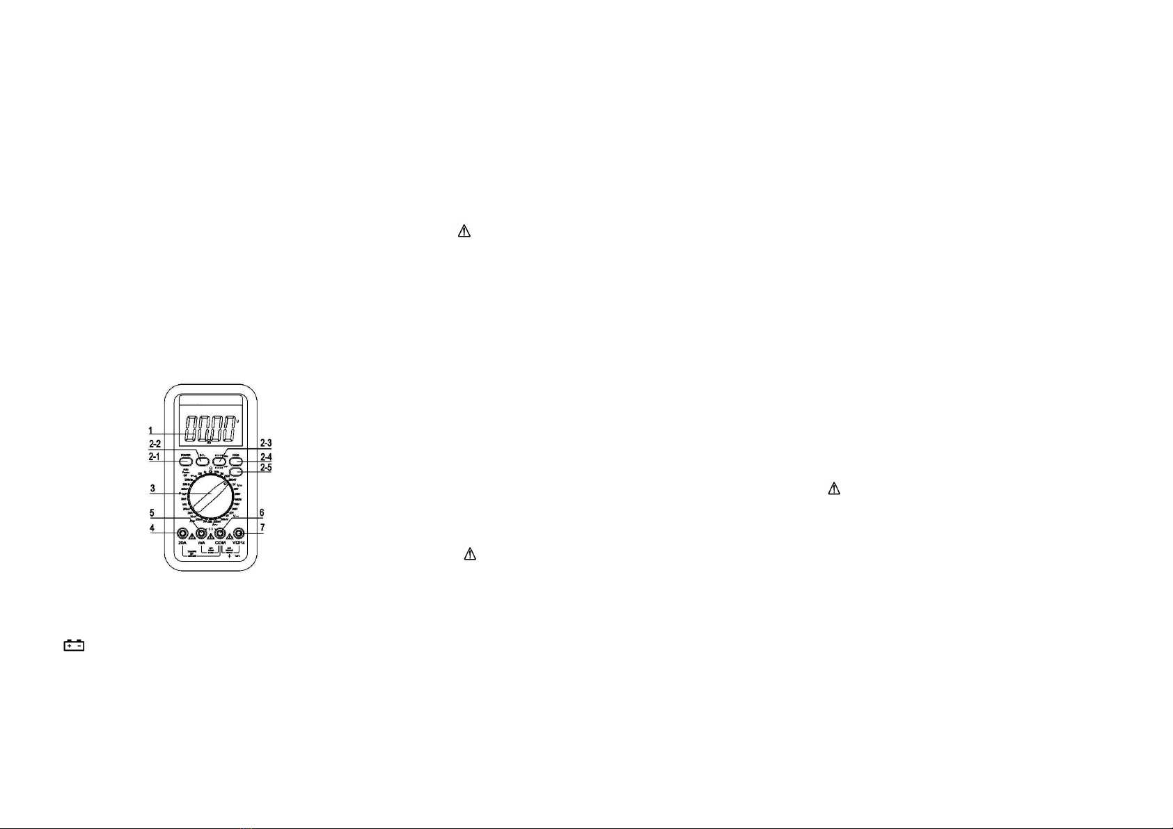
Victor VC9806+ User manual

4 1/2 DIGITAL MULTIMETER OPERATION MANUAL
1.INTRODUCTION
This instrument is a high performance, compact, rugged, battery operated, 4½ digital
multi-meter for measuring DC and AC voltage, DC and AC current, Resistance and diode,
Capacitance and Fre uency, Transistor, Diode and Continuity test. The Dual-slop A/D
converter uses CMOS technology for auto-zero, polarity selection and over-range
indication. Full overload protection is provided. Because of its outstanding features, it is
most suitable for use on production line or lab, R & D, maintenance and repair work.
2.SPECIFICATIONS
2.1 GENERAL SPECIFICATIONS
Display : 4½ digit LCD, Max. 19999 counts with unit indication
Polarity : Automatic negative polarity indication.
Zero adjustment : Automatic.
Measuring method : Dual-slop A/D converter
Sampling rate : 2-3 times/second
Over range indication : Only the MSD “1" display.
Max. Common mode voltage : 500V DC/AC RMS
Low battery : The “ ” is display.
Safety standards : EMC/LVD. The meter is up to the standards of IEC1010
Pollution Degree 2, Over voltage category or double insulation .Ⅱ Ⅱ
Operating environment : Temperature (0 to 40 ), humidity<80%RH.℃ ℃
Storage environment : Temperature (-10 to 50 ), humidity<80%RH.℃ ℃
Power : Single, standard 9 volt battery. NEDA 1604IEC6F22
Dimension : 192mm(H)X95mm(W)X48mm(D)
Weight : Approx. 455g(including 9V battery)
Accessories : Operation manual, Conform card, Test leads(Red & Black 1 pair),
Shock-proof cover, Gift box, etc.
2.2 ELECTRICAL SPECIFICATIONS
Accuracy is ±(percentage of reading + number of digit) at 23±5 ,<75%RH.℃
DC Voltage
Range Accuracy Resolution
200mV ±(0.05%+3) 10uV
2V 100uV
20V 1mV
200V 10mV
1000V ±(0.1%+5) 100mV
Input impedance: 10MΩ
Overload protection: 200mV range: 250VDC/AC RMS
2-1000V rang: 1000VDC/AC RMS
AC Voltage
Range Accuracy Resolution
200mV ±(1.0%+25) 0.1mV
2V
±(0.8%+25)
1mV
20V 10mV
200V 100mV
750V ±(1.0%+25) 1V
Input impedance : 2MΩ
Overload protection: Range 200mV: DC 250V or AC peak value.
Other ranges: DC 1000V or AC peak value
Fre uency response: below 200V range: 40-400Hz
750V range: 40-200Hz
Indication: Average (rms of sine wave)
Resista ce
Range Accuracy Resolution
200Ω ±(0.2%+10) 0.01Ω
2kΩ ±(0.2%+5) 0.1Ω
20kΩ 1Ω
200kΩ 10Ω
2MΩ 100Ω
200MΩ ±
【(5%(reading-10.00)+30】10kΩ
Open circuit voltage: Less than 3V
Overload protection :250V DC/AC RMS
DC Curre t
Range Accuracy Resolution
200uA ±(0.5%+4) 0.01uA
2mA 0.0001mA
20mA 0.001mA
200mA ±(0.8%+6) 0.01A
20A ±(2.0%+15) 0.001A
Max measuring voltage: 200mV
Max input current: 20A(max. up to 15seconds)
Overload protection:Fast 0.2A/250V fuse, 20A range has not fuse.
AC Curre t
Range Accuracy Resolution
200mA ±(1.5%+25) 0.1mA
20A ±(2.5%+35) 10mA
Max measuring voltage: 200mV
Max input current: 20A (max. up to 15seconds)
Overload protection:0.2A/250V self-resume fuse, 20A range has not fuse.
Fre uency response: 40-200Hz
Indication: Average (rms of sine wave)
Capacita ce
Range Accuracy Resolution
20nF ±(4.0%+50) 10pF
2uF 1000pF
200uF 10nF
Measuring fre uency: 400Hz
Overload protection: 36V DC/AC RMS; 630mA/250V
Freque cy
Range Accuracy Resolution
20kHz ±(1.5%+25) 10Hz
200kHz 100Hz
Overload protection: 250V DC/AC RMS (max. up to 15 seconds)
Diode Test
Range
Description
Test Condition
Display read approx. forward
voltage of diode
Forward DC Current approx.
1mA. Reversed DC voltage
approx. 3V.
Buzzer sounds if resistance
Between terminals V/Ωand COM
is less than about 70Ω.
Open circuit voltage is approx.
3V
Overload Protection: 250V DC/AC RMS
Tra sistor hFE Test
Range Description Test Condition
hFE Display read approx. forward
Voltage (0-1000) of transistor under test
(ALL TYPE)
Base Current approx.
10uA, Vce approx. 3V

4-1.Fro t pa el
1.LCD:display the measured value
2-1 Power switch:turn on or off the power
2-2. Backlight key: turn on or off the power
2-3. hFE testing terminal:for measuring
transistor hFE
2-4. HOLD key:press the key down, the
measured value will be hold and“ H ”
signal appears; press it down again,“ H ”
signal disappears and out of the HOLD mode.
2-5.Continuity buzzer key
3.Knob switch: for changing function and range
4. Testing terminal for 20A current
5. Testing terminal for less than 200mA current and conductance
6. Common ground
7. Terminal for Voltage, resistance, and fre uency testing
3.OPERATION
1.Check 9-volt battery by setting the ON-OFF switch to ON. If the battery is weak, a
sign will appear on the display. If this does not appear on the display, proceed as
below. See MAINTENANCE if the battery has to be replaced.
2.The mark, or sign next to the lead jacks, is for warning that the input voltage or current
should not exceed the indicated values.
This is to prevent damage to the internal circuits.
3.The function switch should be set to the range that you want to test before operation.
3.1 DC a d AC Voltage measureme t
1. Connect the BLACK test lead to “COM” jack and RED test lead the “V/Ω” jack.
2. Set the FUNCTION switch to desired DCV or ACV position.
3. Connect the probes across the source or load under measurement.
Note:
1) If the voltage ranges is not know beforehand set the FUNCTION switch to a high
range and work down, until obtain the most accurate reading.
2) When only the figure "1" is displayed, over range is being indicated and the
FUNCTION switch must be set to a higher range.
3) : Do not apply more than DCV1000V/AC700Vrms to the input. Indication is
possible at higher voltages but there is danger of damaging the internal circuitry,
to covert function and range switch, test leads must leave test dot
4) Use extreme caution to avoid contact with high voltage circuits when measuring high
voltage.
3.2 DC a d AC Curre t measureme t
1. Connect the BLACK test lead to “COM” jack and RED test lead the “mA” jack (max
200mA.)
2. Set the FUNCTION switch to desired current range position.
3. Connect the probes in series with the current source to be measured.
4. For current measurement from 200mA to 20A follow generally the above procedure
but connect the RED test lead to "20A" jack.
Note:
1) If the current range is not know beforehand, set the FUNCTION switch to a high
range and work down. Until obtain the most accurate value.
2) When only the figure "1" is displayed over range is being indicated and the
FUNCTION switch must be set to a higher range.
3) : The max input current is 200mA,or 20A depending upon the jack used (Test time
less than 15 seconds). To covert function and range switch, test leads must leave
test dot.
Excessive current will blow the fuse so that must be replaced.
The 20A range has not protected by a fuse.
4) The max terminal voltage drop (burden voltage) is 200mV.
3.3 Resista ce measureme t
1. Connect the BLACK test lead to “COM” jack and RED test lead the “V/Ω” jack.
2. Set the FUNCTION Switch to desired resistance range position.
3. Connect the probes across circuit to be tested.
Caution: Ensure that the circuit to be tested is "dead".
Note:
1) If the resistance value being measured exceeds the max value of the range selected,
and over range indication will be displayed ("1"). Select a higher range, for
resistance of approx. 1MΩand above, the meter may take a few seconds to
stabilize. This is normal for high resistance readings.
2) When the input is not connected, i.e. at open circuit, the figure "1" will be displayed
for the over range condition.
3) When checking in-circuit resistance, be sure the circuit under test has all power
removed and that all capacitor are fully discharged.
4) Don't input voltage. This is to prevent damage to the internal circuit.
3.4 Capacita ce measureme t
1. Setting function switch to F position.
2. Short test capacitance for full discharge.
3. Connect the test capacitor to the input Cx sockets, noting the polarity connections
when re uired.
Note:
1) If the capacitance value being measured exceeds the max value of the range selected,
and over range indication will be displayed ("1"). Select a higher range.
2) Before insert the capacitor into Cx socket, the LCD display may not be zero, the
residual figures will be decreased gradually and could be disregarded, because
measurement result can override this figure, without affecting the accuracy.
3) : Do not connect an external voltage or current to the measuring terminals.
Capacitors should be discharged before insert into Cx socket.
4) Unit: 1uF=103nF 1nF=103pF
3.5 Freque cy measureme t
1. Connect test leads or shield cable to "COM" and "V/ " jack.
2. Set the function switch to the 20kHz range position, and connect test leads or cable
across the source load under test.
Note:
1) Do not apply more than 250V DC/AC rms to the input. Indication is possible at
voltage higher than 10VAC rms, but readings may be out of specification.
2) In noisy environment, it is preferable to use shield cable for measuring small
signal.
3) Use extreme caution to avoid contact with high tension circuits when
measurement high voltage.

3.6 hFE measureme t
4 Setting function switch to hFE position.
5 Determine whether the transistor is NPN or PNP and locate the Emitter. Base and
collector leads. Insert the leads into the proper holes in the socket on the front panel.
6 The display will read the approximate hFE value at the test condition Base Current
10uA, Vce approx. 2.8V.
3.7 Diode a d co ti uity Test
1. Connect the BLACK test lead to “COM” jack and RED test lead the “V/Ω” jack..
(Note: The polarity of the red test probe is “+”).
2. Set the FUNCTION switch to “ ” position.
3. Connect the test leads across the diode under measurement, display shows the
approx. forward voltage of this diode.
4. Connect the test probes to two points of circuit, if the resistance is lower than approx.
70Ω. Buzzer sounds.
Note:
1) When the input is not connected, i.e. at open circuit, the figure "1" will be displayed.
2) There is a milliamp current flow through the diode under test.
3) The meter displays the forward voltage drop in millivolts and overload when the
diode is reversed.
4. WARNING
1. When measuring voltage ensure that instrument is not connected or switched to a
current or resistance range, or to the diode check. Always ensure that the correct
terminals are used for the type of measurement to be made.
2. Use extreme care when measuring voltage above 50V, especially from sources where
high energy is existed.
3. Avoid making connections to “live” circuits whenever possible.
4. When making current measurements ensure that the circuit not “live” before opening
it in order to connect the test leads.
5. Before making resistance measurements or diode test, ensure that the circuit under
test is de-energized.
6. Always ensure that the correct function and range is selected. If in doubt about the
correct range to use, start with the highest and work downwards.
7. Extreme care should be taken when using the instrument to conjunction with a
current transformer connected to the terminals if an open circuit occurs.
8. Ensure that the test leads and probes are good condition with no damage to the
insulation.
9. Take care not to exceed the over-load limits as given in the specification.
10. FUSE FOR REPLACEMENT MUST BE OF THE CORRECT TYPE AND
RATING.
11. Before opening the case of the instrument to replace battery or fuse, disconnect the
test leads from any external circuit, set the POWER switch to “OFF” position.
5. CARE AND MAINTENANCE
5.1Care for your multi-meter
Your Digital Multi-meter is an example of superior design and craftsmanship. The
following suggestions with help you care for the multi-meter so you can enjoy it for year.
1) Keep the multimember dry. If it gets wet, wipe it dry immediately. Li uids can
contain minerals that can corrode electronic circuits.
2) Use and store the multi-meter only in normal temperature environments.
Temperature extremes can shorten the life of electronic devices, damage batteries, and
distort or melt plastic part.
3) Handle the multiyear gently and carefully. Dropping it can damage the circuit boards
and case and can cause the multi-meter to work improperly although the holster can
provide enough protection.
4) Keep the multi-meter away from dust and dirt, which can cause premature wear of
parts.
5) Wipe the multi-meter with a damp cloth occasionally to keep it looking new. Do not
use harsh chemicals, cleaning solvents, or strong detergents to clean the multi-meter.
6) Use only fresh battery of the re uired size and type. Always remove old or weak
batteries.
They can Leak chemicals that destroy electronic circuits.
5.2 Mai te a ce
1) 9-Volt battery replacement
a. Ensure the instrument is not connected to any external circuit. Set the selector
switch to OFF position and remove the test leads from terminals.
b. Remove the screw on the bottom case and lift the bottom case.
c. Remove the spent battery and replace it with a battery of the same type.
2) Fuse replacement
a. Ensure the instrument is not connected to any external circuit. Set the selector
switch to OFF position and remove the test leads from terminals.
b. Remove the screw on the bottom case and lift the bottom case.
c. Replace the fuse with same type and rating: 5x20mm, 200mA/250V, fast-blow
fuse or as the replacements.
Other Victor Multimeter manuals

Victor
Victor VC921 User manual

Victor
Victor 81D User manual

Victor
Victor 70D User manual

Victor
Victor VC890D User manual

Victor
Victor VC9807A+ User manual

Victor
Victor VC9808+ User manual

Victor
Victor VC70D User manual

Victor
Victor VR-9807A User manual

Victor
Victor VC9808 User manual

Victor
Victor 6000counts User manual