CAUTION:DO NOT INPUT VOLTAGE AT THIS RANGE!
2-3-11. Transistor hFE DATA TEST
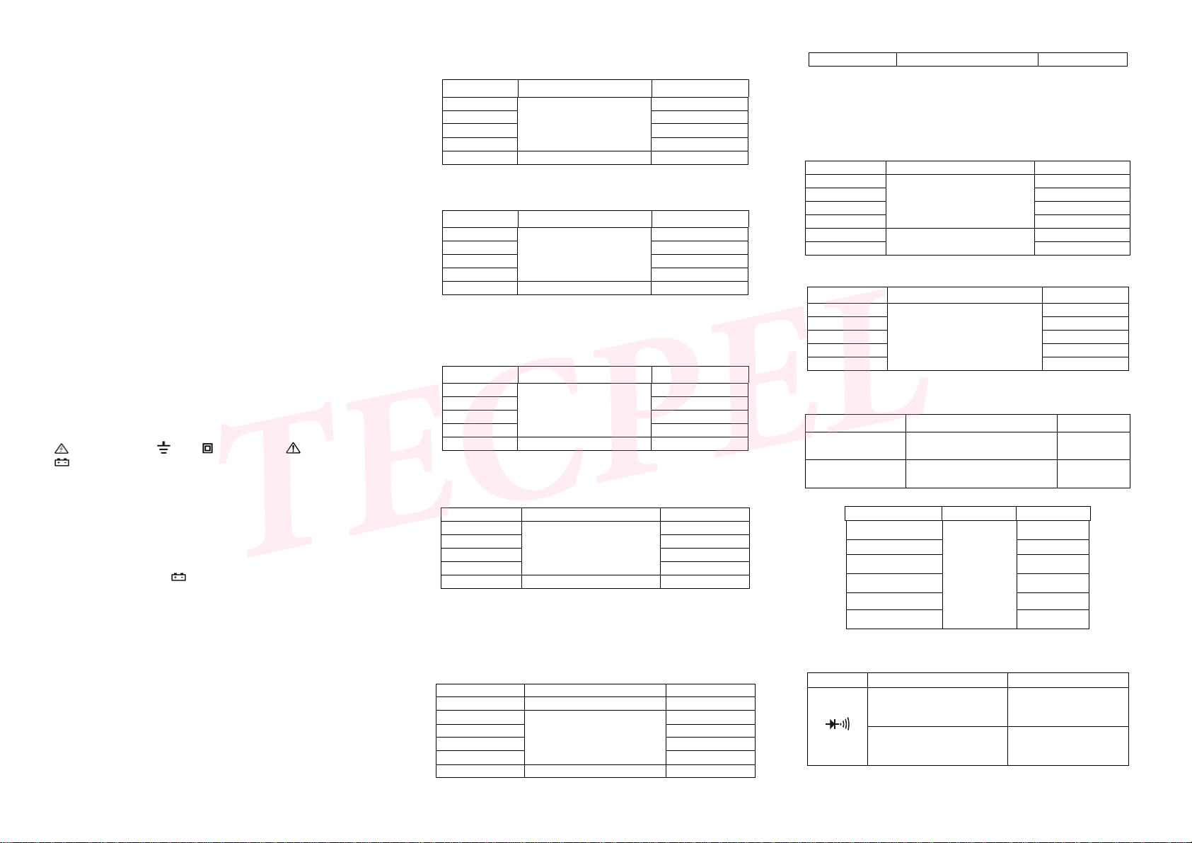
Range Displaying range Test condition
hFE NPN or PNP 0 ~ 1000β Basic current is approx.
10uA , Vce is about 3V
4. OPERATION
4-1.Panel description
1. LCD: display the measuring value and unit.
2. Press “REL/MAX/MIN”, then you can test the
relative magnitude. If you hold the “REL/MAX/MIN”
for more than 2s, you can test the Max and Min
value.
3. Transistor input jack
4. Backlight and function key; Diode/buzzer and
frequency range, when press ”HOLD/B/L”, you can
do the function change; When under other range, this
is the hold key; press “HOLD/B/L” key for more than
2s, the backlight will on/off.
5. Power on/off
6. Switch: change the function or the range.
7. 200mA current and inductance input jack
8. 20A/2A current test jack
9. Inductance, temperature, “-“common input jack
10. Voltage, resistance, diode, capacitance, frequency, temperature, “+” input jack.
SEE THE FIG.
4-2.Voltage measurement
1. Apply the black test lead to “COM” terminal and the red one to “V/Ω/Hz” terminal.
2. Setup the Knob on a proper range “V”. If the voltage range is unsure beforehand,
please set it on the max., then measure diminishingly to reach a resolute value.
3. Press the DC/AC key down to AC mode to measure AC voltage. Oppositely,
resile the key to DC mode to measure DC voltage.
4. Connecting the test leads reliably with the tested circuit, the voltage value will be
displayed on LCD. While testing a DC voltage, the reading is voltage and polarity of
the point connected by the red lead.
NOTE:
1. While the reading is “OL”,the voltage is beyond the present range. Now you need
to set the knob to the higher.
2. Do not input a voltage over DC 1000V or AC 750V. Please keep the test leads off
the circuit while switching the function or range, or after finished your testing.
3. Be carefully while measuring a high voltage. DO NOT touch the circuit.
4-3.Current measurement
1. Apply the black test lead to “COM” terminal and the red one to “mA” (Max 200mA)
or “20A”(Max 20A) terminal.
2. Set the knob to a proper range “A”. If the current under tested is unsure
beforehand, please set it on the max., then measure diminishingly to reach a
resolute value.
3. Press the DC/AC key down to AC mode to measure AC current. Oppositely,
resiling the key to DC mode to measure DC current.
4. Connecting the leads with the tested circuit in series, the current value is
displayed on LCD. While testing a DC current, the reading is the value of current
and polarity of the point connected by the red lead.
NOTE:
1.If the LCD displays “OL”,it means the current is over range. Now you need to set
the knob to the higher.
2.Max. input current is 200mA or 20A(subject to where the red test lead apply to),
too large current will blow the fuse. Be sure the test is less than 10 seconds when
test 20A current. Please keep the leads off the circuit while switching the function
and range knob.
3. Do not input more than DC 36V, AC 25V between the current jack and “COM”
jack.
4-4.RESISTANCE MEASUREMENT
1. Apply the black lest lead to “COM” terminal and the red one to “V/Ω/Hz” terminal.
2. Set the knob to a proper resistance range, and connect the leads crossly with the
resistor under tested.
NOTE:
1. The LCD displays “OL” while the resistance is over the selected range. The knob
should be adjusted to a higher range.
2. When test low resistance, test leads will bring internal resistance, in order to get a
accurate readings, you can mark the short circuit value of the test leads, then
subtract it from the value of the low resistance.
3. When measuring in line resistor, be sure that the power is off and all capacitors
are released completely.
4. Do not input any volt at resistance range.
5. When measuring value is over 1MΩ, the reading will take a few seconds to be
stable. It’s normal for high resistance measuring.
4-5.CAPACITANCE MEASUREMENT
Apply the knob to proper capacitance range, and insert the capacitor under tested
into “V/Ω/Hz” and “COM” terminal, be wary of polarity if necessary.
NOTE:
1. If the capacitance under tested is over the max. value of selected range, LCD
displays “OL”, thus, should set the knob to a higher range.
2. It’s normal that there is a remained value on LCD before capacitance
measurement when at the range 20nF and you can subtract it from the value.
3. When measuring at large capacitance range, if capacitor is crept badly or broken,
LCD displays a value and it’s unstable.
4. Release the capacitor completely before measuring.
4-6.INDUCTANCE MEASUREMENT
Set the knob to a proper inductance range and insert the inductor to “mA” and
“COM” terminal.
NOTE:
1. The LCD displays “OL” while the tested inductance is over the selected range.
Thus, the knob should be set to a higher range.
2. Range “mH” is auto change of 2mH/20mH/200mH, and range “H” is the auto
range of 2H/20H.
3. Do not input voltage at this range.
4-7. FREQUENCY MEASUREMENT
1. Apply test leads or shield cable to “COM” and “V/Ω/Hz” terminal.
2. Set the knob to frequency range, connect test leads or cable crossly to signal
source or tested load.
NOTE:
1. When input over 10V RMS, reading is workable but accuracy is not guaranteed.
2. It is better to use shield cable to measure small signal at noisy environment.
3. Be careful when measuring high volt circuit.
4. Do not input voltage over DC 250V or AC peak value.
4-8. TRANSISTOR hFE
1. Set the knob to “hFE” range.
2. Verify the transistor under tested is NPN or PNP, insert emitter, base and
collector to proper jack.
4-9. DIODE AND CONTINUITY TEST
1. Apply the black test lead to “COM” terminal and the red one to “V/Ω/Hz” terminal
(the polarity of red lead is “+”).
2. Set the knob to range, connect test leads to the diode under tested, the
red test connect to diode positive polarity, the reading is the approx. value of diode
forward volt drop.
3. Apply test leads to two points of tested circuit, if the inner buzzer sounds, the
resistance is less than (50 ± 20) Ω.
NOTE: Do not input voltage at this function.
4-10.DATA HOLD/ BACKLIGHT
Except Diode, Buzzer and Frequency function, at all other functions, if you press
“HOLD B/L”, it will show “HOLD” symbol on the display, and the present value will
be keep on it too, and if you press the key again, the symbol will disappear. If you
press the key for more than 2s, it will be the backlight on/off.
4-11.AUTO POWER OFF
After stop working for 15 minutes, the meter will be into sleep mode. Press
“POWER” key can back to work.
Press “REL/MAX/MIN” key and at the same time press the “POWER” the “APO”
symbol will disappear, now you already closed the function of auto power off.
5.MAINTENANCE
Do not try to modify the electric circuit.
5-1. Keep the meter away from water, dust and shock.
5-2. Do not store and operate the meter under the condition of high temperature,
high humidity, combustible, explosive and strong magnetic place.
5-3. Wipe the case with a damp cloth and detergent, do not use abrasives and
alcohol.
5-4. If do not operate for a long time, should take out the battery to avoid leakage
When signal displays, should replace the battery following the steps
5-4-1 Unlock the button and remove the battery case.
5-4-2 Take out the old battery and replace the new one. It’s better to use alkaline
battery for longer life.
5-4-3 Fit on the battery case, lock the button and put on the holster.
5-5 Replace fuse :When replacing fuce, please use another same type and
specification fuse.
6. If the meter does not work properly, check the meter as following:
Fault Solution
No reading on LCD
●Power off--- Pls turn on the power
●Holding key---PLs set a correct mode
●Replace battery
The signal appears ●Replace battery
No current or temperature input ●Replace fuse
Error Value ●Replace battery
601E-9805-002A