Solimar Air Knocker Series User manual

KNR-30-DI / KNR-40-DI KNR-60-DI / KNR-80-DI KNR-100-DI
KNR-20
KNR-20-SS
KNR-30 / KNR-40
KNR-30-SS / KNR-40-SS
KNR-60 / KNR-80
KNR-60-SS
KNR-100
Since 1985
Instruction Manual
AIR KNOCKER SERIES
KNR-15-SS

32
• The Air Knocker is designed to prevent materials from adhering to or blocking flow in process
equipment by using forced air. Do not use the Air Knocker for any other purpose.
• Care has been taken to ensure the safety of the Knocker. Be sure to read this instruction
manual and note the warning and caution messages before using the Knocker.
• The following symbols represent warning and caution messages to be observed when using
the Knocker to prevent injury or damages to users or other persons.
Refers to a hazard that may cause death or serious injury.
Refers to a hazard that may cause slight or medium injury.
WARNING
TO PREVENT DEATH:
• After installing the Knocker, make sure to attach the fall prevention wire to it to
prevent it from falling due to percussion during operation.
• In the event that the Knocker falls, be sure to replace the fall prevention wire even if
it appears to be undamaged.
• Do not connect the electric control devices (Knocker control board or three-way
solenoid valve) for the Knocker to a power source which is not equipped with a
breaker for preventing electric shock.
CAUTION
TO PREVENT INJURY OR DAMAGES:
• When removing the piping tube, please be sure to close the air supply from the
control equipment and to release the air pressure which remains in the Knocker. If
the tube is removed while air pressure still remains, the Knocker will operate, and
there is a possibility of an unexpected injury.
• Securely weld Knocker base to the vessel so that the Knocker does not fall due to
percussion during operation.
• If the vessel metal thickness is too thin, weld a reinforcing plate onto it to prevent
the mount plate from being damaged as a result of impact during operations.
WARNING
CAUTION
Safety Precautions
• Be sure to read this instruction manual carefully before using the Knocker.
• Handle the Knocker appropriately and inspect it to maintain its performance.
• Keep this manual for future reference.
Safety Precautions 2
Warning 2
Caution 2
Introduction 3
Safety 4
Caution (For personal protection during operation) 4
Caution (For longer service life) 5
Names of Parts 6
Installation 8
Piping 11
Test Operation and Settings Before Use 15
Inspection 15
Replacement Period for Consumables 16
Troubleshooting 16
Specifications 17
Dimensions 18
Introduction
Contents
54
Safety
CAUTION
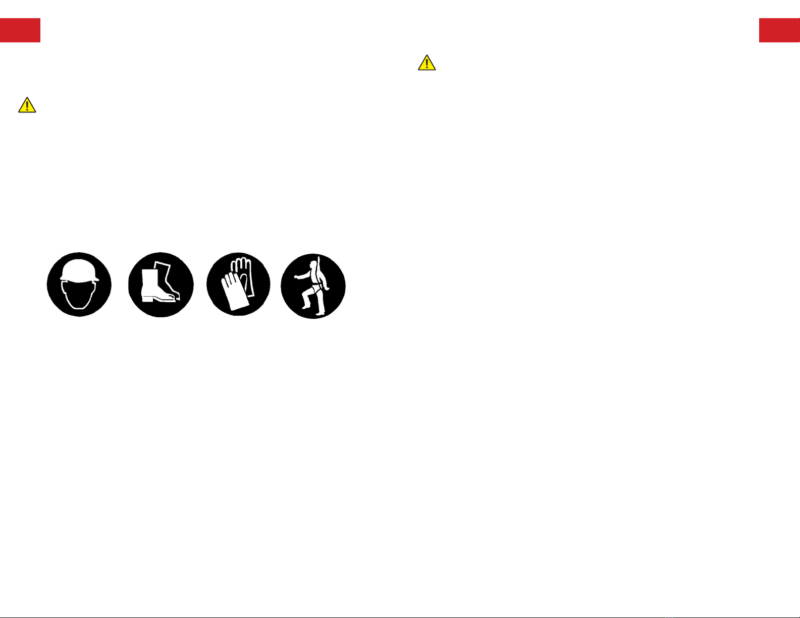
FOR PERSONAL PROTECTION DURING OPERATION:
• Put on a safety helmet, safety boots, safety gloves and a safety belt, before any
installation work is started.
• Conduct all required lock-out, tag-out or similar required procedures prior to inspection
or repair.
• When using the fall prevention wire to prevent Knocker from falling, be sure to secure
shackle with appropriate tie to prevent shackle screw from loosening from percussion
during operation.
CAUTION
FOR LONGER SERVICE LIFE:
• When installing the air line, include a filter or filter/regulator prior to the Solenoid
valve to minimize dust getting into the Solenoid valve, which may inhibit the Knocker
from operating properly.
• Make sure the force of impact does not exceed the maximum level, as excessive
impact may damage the vessel it is mounted on.
• When applying continuous impact at short cycles, allow an interval of at least one
second. An interval of less than one second may lead to damage or operation
problems.
• Only start air lines after checking that there is no foreign substance, chips, or slag
on the piping materials.
• Flush with the air pressure of 44 psi or more, to clean any debris or contamination
in the piping.
• Use air that passed through an air filter 5 micrometers or less. Moisture or dust in
line will potentially cause poor operation and air leakage.
• The line should connect to the IN side in the direction of the flow and to the IN port
displayed on the product.
• Do not use in an area with corrosive explosive gas.
• When using a sealant, be careful to keep from inside the line, and seal to prevent
external leaks. When wrapping sealing tape around the screw part, wrap the tip of
the screws leaving 2 to 3 threads. Also, when using a liquid sealant, coat leaving 2
to 3 threads. Do not coat the female screws of the equipment. Tighten and check
for air leaks.
• In cold areas, please protect against freezing. (Air should not freeze)
• Avoid placing a heavy load on the lines.
• Operation air should contain some moisture or light oil. Operating using dry air may
shorten the product’s life cycle.
Safety
Helmet
Safety
Boots
Safety
Gloves
Safety
Belt
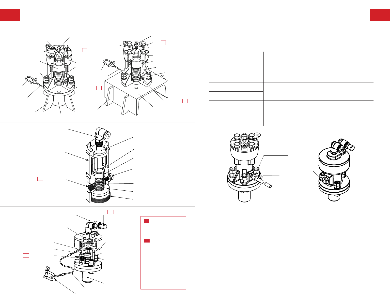
76 Names of Parts
#1 Using relay piping,
remove the blank plug
and insert a relay piping
tube in the outlet.
#2 When using a
Knocker where exhaust
air must be directed
away from installation
site, please screw a
tube connector into the
Knocker’s exhaust hole,
and make exhaust air
discharge outside with
an extension tube. A
sintered metal exhaust
filter may also be used.
KNR Models KNR-DI Models
KNR-15-SS
Extension Tube / Tube Connector Option
Model (KNR-) Dia. of Exhaust
Hole Screw
I.D. of
Recommended Tube
Max. Distance of
Extension Tube
15-SS 1/8 NPT 1/4” 130 ft.
20 / 20-SS 1/8 NPT 1/4” 130 ft.
30 / 30-DI /30-SS
1/4 NPT 5/16” 130 ft.
40 / 40-D I / 40-SS
60 / 60-DI / 60-SS 3/8 NPT 3/8” 130 ft.
80 / 80-DI 1/2 NPT 1/2” 130 ft.
100 / 100-DI 3/4 NPT 1/2” 130 ft.
When Discharge Exhaust Outside When Use Exhaust Filter
Exhaust filter
Tube connector
Extension tube
Push-one elbow
C
y
linder
Mushroom valve
Piston
Piston ring
Spring
Exhaust port
Impact plate
Inner base
Bolt M5
Mushroom valve
Wire assembly
Shackle
Push-one elbow Plug
Spring
Exhaust port
Double nut
Cylinder
Base assembly
Piston ring
Piston
#2
#1
#2
Push-one elbow
C
y
linder
Mushroom valve
Piston
Piston ring
Spring
Exhaust port
Impact plate
Inner base
Bolt M5
Mushroom valve
Wire assembly
Shackle
Push-one elbow Plug
Spring
Exhaust port
Double nut
Cylinder
Base assembly
Piston ring
Piston
#2
#1
#2
Wireassembly
Shackle
Hardlocknut
Tubeconnector
Airsupplyandexhaustopening
Plug#1
Mushroomvalve
Airtank
Cylinder
Piston
Exhausthole#2
Plug #1
Tubeconnector
Airtank
Piston
Exhausthole#2
Base
Reinforcingrib
Cylinder
Shackle
Wireassembly
Hardlocknut
Airsupplyandexhaustopening
Baseassembly
Reinforcingrib
KNR-20
KNR-20-SS

98
2. WELDING THE REINFORCING PLATE:
• If the vessel wall thickness is too thin, weld a reinforcing plate onto it. Welding procedure should use
all-around welding so that no gap arises between the vessel and the reinforcing plate. Leave one spot
unwelded for bleeding air. If no spot is left unwelded for bleeding the air, the air creates a cushion,
dampening the effect of impact.
• A large impact force is transferred to the reinforcing plate at the time of operation. In order to avoid
failure, install as instructed.
Reinforcing Plate Size (inches)
Model (KNR-) Square Type Round Type ΦAΦBC
30 / 30-SS / 30-DI □6 × t1/8 Φ6 × t1/8
5/8
3/4
2
40 / 40-SS / 40-DI □8 × t1/8 Φ8 × t1/8 3
60 / 60-SS / 60-DI □12 × t3/8 Φ12 × t3/8
2
3 1/2
80 / 80-DI □16 × t3/8 Φ16 × t3/8
1
4 3/4
100 / 100-DI □20 × t1/4 Φ20 × t1/4 3 3/8 5 1/2
Welding
Installation
Welding
3/8 inch 3/8 inch
C C
Reinforcing Plate
Air deflation
ΦB ΦB
KNR - DI
Welding
Air deflation
3/8 inch 3/8 inch
ΦA
Reinforcing Plate
ΦA
KNR
1. INSTALLING POSITION
INSTALLING POSITION
For small cone,pyramid hopper. For large cone,pyramid hopper.
In case of clinging on the surface
of wall and the inside pipe.
In case of bad fluid materials.
L
1/3L
L
1/2L
L
1/2L
L
1/2L
L
L
1/3L
1/4L
L
1/3L
L
1/3L
INSTALLING POSITION
For small cone,pyramid hopper. For large cone,pyramid hopper.
In case of clinging on the surface
of wall and the inside pipe.
In case of bad fluid materials.
L
1/3L
L
1/2L
L
1/2L
L
1/2L
L
L
1/3L
1/4L
L
1/3L
L
1/3L

1110
<Attach to flat surface><Attach to curved surface>
Long reinforcing ribs
Base assembly
Reinforcing plate
(Not required for KNR 20 / 20-SS)
Hopper
Per
p
endicular line of the ho
pp
er
Attaching surface Attaching surface
3. WELDING THE BASE ASSEMBLY AND REINFORCING RIB:
• Cut the reinforcing rib to match the configuration of the part to which it is to be mounted.
• Orient the holes in the base so that exhaust port of Knocker faces downward.
• Use all-around welding to weld the base assembly and make sure that the bolt holes on the right and
left sides are symmetrical.
KNR-DI Models KNR Models
KNR Model: Install Reinforcing Rib
Install to Plane Surface Install to Curved Surface
Reinforcing rib
Cut as adjust curved surface
Baseassembly
Reinforcingrib
Reinforcing
palate
Baseassembly
Reinforcingrib
Reinforcing
palate
Baseassembly
Reinforcingrib
Reinforcing
palate
Baseassembly
Reinforcingrib
Reinforcing
palate
ORIENTATION BASE ASSEMBLY
Please make sure that the holes in the vessel and the base are
correct so that the exhaust port of the Knocker faces downward.
KNR 20
KNR 30 /40 /60 /80

1312
4. MOUNTING THE KNOCKER:
When attaching Knocker unit and base with bolt set, pay attention to
the torque to prevent loosening by the impact of the Knocker.
Wire Assembly
Clamp Torque Nut Size
Model (KNR-) 20 30 40 60 80 100
Nut Size M6 M8 M12 M14 M16 M20
Tightening
Torque
(lbf • ft)
Lower Nut 4.0 8.0 26.0 42.0 62.0 123.0
Upper Nut 4.0 6.0 18.0 29.0 44.0 86.0
Model (KNR-) Wire Diameter Wire Length Shackle
15-SS
1/16
12
5/32
20 /20-SS 6
30 /30-DI /30-SS
3/32
7
1/4
40 /40-DI /40-SS 14
60 /60-DI /60-SS
1/8 17
80 /80-DI
100 /100-DI 3/16 20 5/16
• To prevent falling, suspend the Knocker by the wire and the shackle.
• Adjust the position of the metal fittings so that the wire assembly does not loosen.
Knocker Bolt Set
* The washer is not attached to KNR-20/KNR-20-SS.
The bolt set is unnecessary in KNR-15-SS.
* The fall prevention wire is an option. (KNR 15-SS)
Knocker
Bolt set
Upper nut
Lower nut
Spring washer
*1 Washer
Bolt
Base assembly
Knocker
Bolt set
Upper nut
Lower nut
Spring washer
*1 Washer
Bolt
Base assembly
Hanging metal fittings
Wire assembly
The wire assembly is
an option.
Shackle
Wire assembly
Exhaust port of
the knocker body
becomes downward
Wire assembly fixes with
this bolt.
Shackle
Exhaust hole of the knocker
body becomes downward
Wire assembly
Prescribed Dimensions
Prescribed Dimensions
Model (KNR-) Dim X
30-DI 2
40-DI 3
60-DI
3.5
80-DI
100-DI
Dim X
5. PRESCRIBED DIMENSIONS FOR THE KNR-DI MODEL MOUNTING:
If not using the base assembly provided, make sure that the dimensions of the part to which the
Knocker is mounted and the base mounting part meet the prescribed dimensions listed below.
Effective Length: 9.5mm
t (mm) L
Less than 4mm 1M10 × 14
From 4 to less than 6 M10 × 16
From 6 to less than 8 M10 × 18
KNR-15-SS:
• The KNR-15-SS type uses M10 bolts.
• Please strictly observe the torque specs for bolts.
• Bolt size and material: M10 SUS or M10 SS
• Clamp torque: 12.5 lb•ft•
L: length of bolt t: thickness of plate
An additional washer with thickness of at
least 2mm must be used with wall thickness
less than 2mm
Bolt M10
(inches)
(inches)

1514
Piping
• Select either standard or relay system piping per the examples below.
• When only one system is used with the control board (HKA and EKE models), place a
blind stopper in the unused system.
• In the control board (HKA and EKE models), the Knocker can be connected to line A or
line B, but note that the pressure accumulation and percussion operations are reversed
on one system.
1. EXAMPLE IN STANDARD PIPING: A/B/C
A. When using a three-way solenoid valve:
B. When using the HKA and EKE model exclusive control board:
C. When using the air operation controller KNR-CONTROL AOC model:
5/16 OD
KNR-CONTROL AOC
OFF
ON
When using the air operation controller KNR-CONTROL AOC
Air Knocker
Exhaust
Filter Regulator
Compressor
Control panel
Power Source
5/16 OD
A line
B line
Exhaust
When using the HKA, EKE exclusive control panel
Hopper
Air Knocker
Filter Regulator
Compressor
2. TUBE LENGTH IN STANDARD PIPING
• Make air lines as short as possible to maximize the impact force.
• The maximum length of a piping tube changes with model, air pressure,
and control unit, and may decrease Knocker effectiveness by 10 to 20%.
• When adding another pipe, the length of the tube from the branch point to each Knocker
should be equal.
• Avoid extreme bending and adding extra lines. It may affect operation and impact force
especially in units furthest from the air supply.
• It is recommended to set the minimum tube pressure at 44 psi to maintain stable
performance. Impact force can be maintained by increasing air pressure.
• When arranging the piping between the Knocker and the control devices, use nylon or
urethane tube which has a OD of 5/16 in.
A. When using the solenoid valve:
B. When using the HKA and EKE model
exclusive control board (per system):
C. Maximum Tube Length (ft) between KNR-CONTROL AOC and Knocker:
Model (KNR-) Tube Length (ft)
15-SS / 15 6.5
20 / 20-SS / 20 6.5
30 / 30-SS / 30-DI 6.5
40 / 40-SS / 40-DI 9.75
60 / 60-SS / 60-DI 26.25
80 / 80-DI 32.75
100 / 100-DI
80 / 80-DI
100 / 100-DI
40 / 40-SS / 40-DI
60 / 60-SS / 60-DI
30 / 30-SS / 30-DI
20 / 20-SS
15-SS
66
49
32
16
0
Pressure (PSI)
Tube length (feet)
When using solenoid valve
44 58 73 87 102
Pressure (PSI)
80 / 80-DI
100 / 100-DI
40 / 40-SS / 40-DI
60 / 60-SS / 60-DI
30 / 30-SS / 30-DI
20 / 20-SS
15-SS
262
197
131
66
044 58 73 87 102
Tube length (feet)
When using the HKA, EKE model exclusive control panel (per system)
When using with three-way solenoid valve
Compressor
Filter Regulator
Timer1 Complex timer or Switch
Timer2
Air Knocker
Hopper
OUT IN
EXH
1716
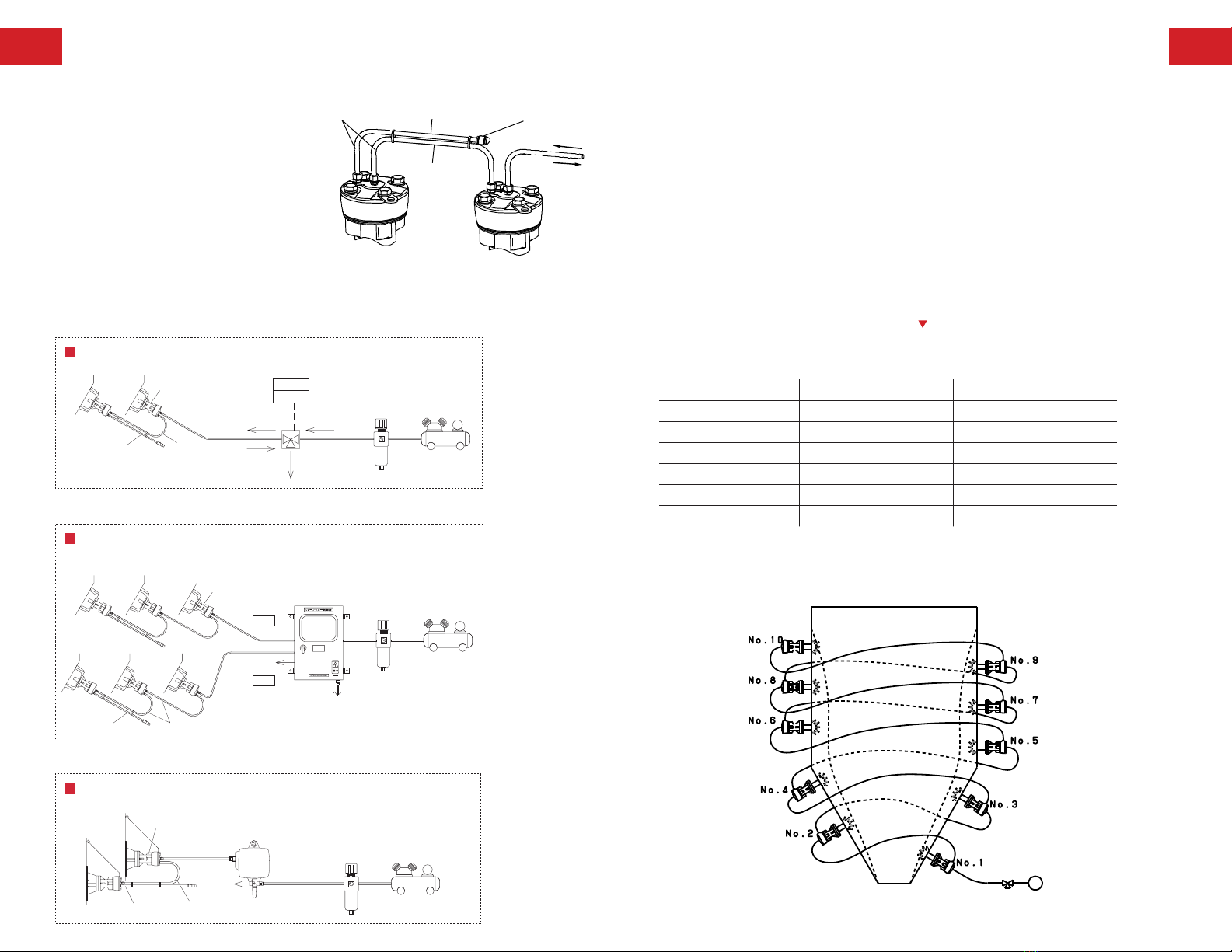
3. EXAMPLE IN RELAY SYSTEM PIPING: D/E/F
• Relay system piping method that connects two or
more Knockers in series. This method is connecting
a relay tube from air tank of the Knocker (cross
valve side) to air supply and exhaust opening of
another Knocker.
• When using relay system piping, Knocking action
starts in order from a Knocker that is located
in cross valve side to other Knockers. The
maximum number of Knocker that can be used
is regulated by the type of control.
• When arranging relay piping, please set the
actuation of the solenoid valve at 1 second or more. When the tube length of relay piping becomes
long and/or the number of relay pipes increase, please extend actuation of the solenoid valve.
D. When using the three-way solenoid valve model (maximum 5 units):
E. When using the HKA and EKE model exclusive control board (maximum 10 units per system):
F. When using the air operation controller KNR-CONTROL AOC model (maximum 3 units):
Dummy tube
Relay tube
Tube cap
Intake
Exhaust
Knocker
K
nocker
No.2 No.1
Make the length of the
p
i
p
in
g
tubes e
q
ual
5/16 OD
When using the HKA, EKE exclusive control panel
Hopper
Air Knocker
Relay tube
Dummy tube
Hopper
A line
B line
Exhaust
Power Source
Control panel
Compressor
Filter Regulator
Relay tube
5/16 OD OUT
Dummy tube
When using with three-way solenoid valve
Hopper Air Knocker Timer1
Timer2
Compressor
Filter Regulator
Complex timer or Switch
IN
EXH
KNR-CONTROL AOC
OFF
ON
5/16 OD
When using the air operation controller KNR-CONTROL AOC
Exhaust
Compressor
Filter Regulator
Air Knocker
Relay tube
Dummy tube
4. TUBE LENGTH OF RELAY SYSTEM PIPING AND AIR PRESSURE
• In relay system piping, compressed air in the relay tube is also used for operation air of the Knocker.
Accordingly, the air pressure is not to exceed the regulated valve. (Refer to length of relay tube in
relay system piping and air pressure)
• Use 5/16 OD nylon or urethane tube when arrange piping between Knockers and control
equipment. (Please use 1/4 OD tube for KNR-20.)
• Arrange tube length to the first Knocker as referenced in standard piping, section 2.
• It is recommended to connect a piece of dummy tube (that is same length as the relay tube) to the
terminal Knocker, so the knocking force of every Knocker is equal. (Refer to Section 3. Example of
relay system piping - pg. 13)
• In order to prevent an air leak, please equip the end of the dummy tube with a cap.
• In relay system piping, the knocking force increases when the tube length is extended but it will effect
the durability of the Knocker unit.
• Length of connecting tube (relay tube) for 2nd and other Knockers are dependent on the type of
Knocker. Length between is not to exceed the maximum length. Also, make the length as even as
possible to balance knocking force. (Refer to table)
Knocking force at value listed above is equivalent to the knocking force at maximum air
pressure (102 psi) in standard piping
Start Knocking in Order from No. 1
(From Lower to Upper)
Length of Relay Tube in Relay System Piping and Air Pressure
Model (KNR-) Relay Tube Length (ft) Working Pressure (PSI)
20 / 20-SS / 20 3.25 or less 44 or above
30 / 30-SS / 30-DI 3.25 or less 44 or above
40 / 40-SS / 40-DI 16.5 or less 58 or above
60 / 60-SS / 60-DI 16.5 or less 73 or above
80 / 80-DI 32.75 or less 73 or above
100 / 100-DI 32.75 or less 80 or above

1918
Test Operation and
Settings Before Use
After mounting and piping the Knocker, run a test operation and complete the settings in
accordance with the following procedure:
1. Set the air pressure to 44 psi. (14.5 psi at relay piping)
2. Set the most suitable air pressure in the regulated range by increasing the air pressure
of the regulator 5 psi apiece.
Note: The farther the Knocker is from the regulator, the lower the pressure at the Knocker compared to the
pressure indicated at the regulator. In such a configuration, set the pressure slightly higher.
Inspection
Inspect the following items at least once every three months to minimize trouble during operation:
1. Are any nuts or bolts loose?
2. Are any welded parts cracked?
3. Have any contaminants gotten into the Knocker?
4. Is there any abnormal wear on the cylinders or pistons?
5. Is there any spring damage?
6. Is there any damage to safety wire assembly?
Replacement Period
For Consumables
Replace consumables as set out in the following table:
Note: Contact the branch, sales office or designated service center closest to you for repair or overhauling of the Knocker
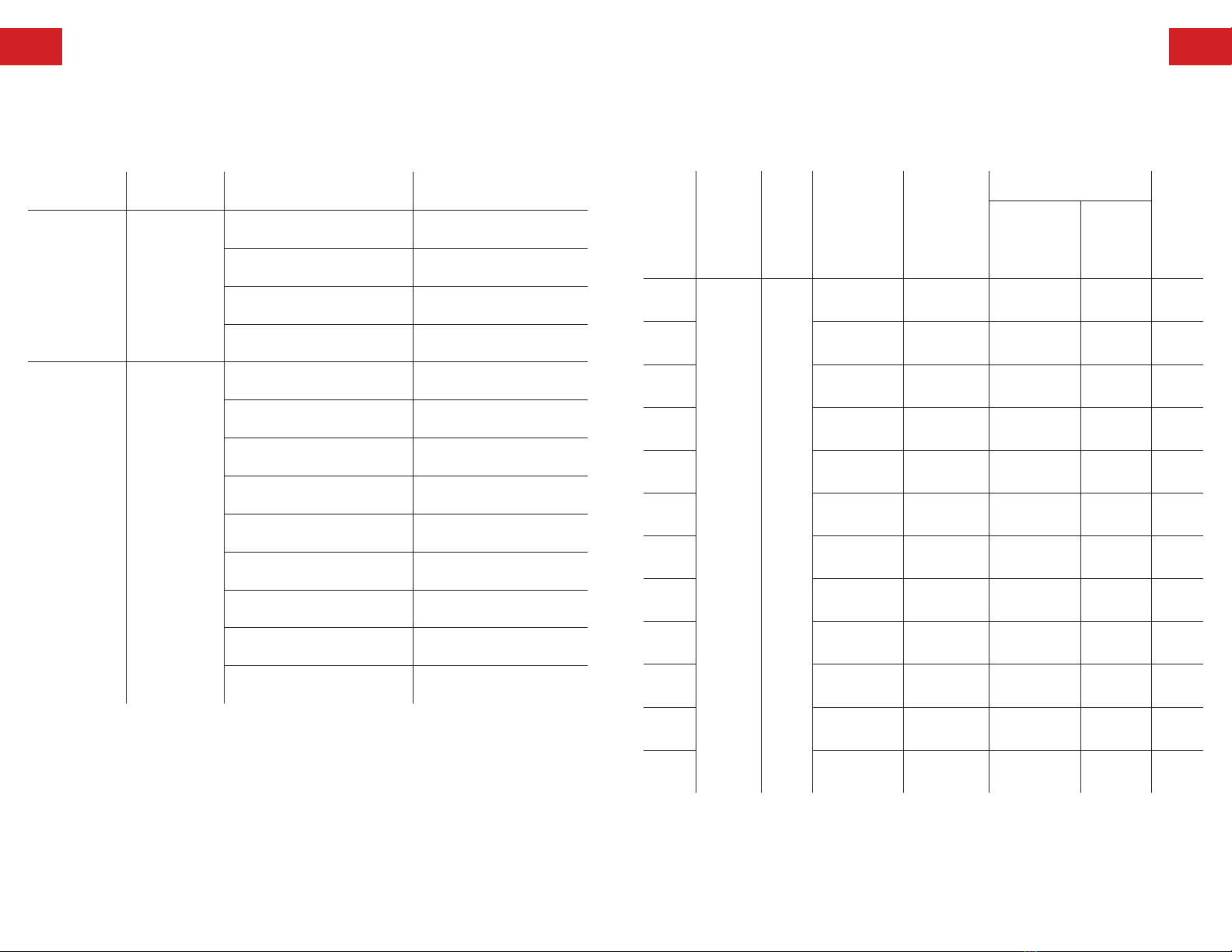
Part How to determine the replacement period
from visual and audible signs
Replacement
Period
(Average)
Mushroom
Valve
Determine according to the amount of wear,
scratches and cracks (visual)
1,000,000
Strokes
Piston Determine according to the amount of wear (visual) 1,000,000
Strokes
Spring Determine according to the amount of wear
and operation conditions (Visual and audible)
1,000,000
Strokes
Spring Determine according to the amount of wear
and operation conditions (Visual and audible)
1,000,000
Strokes
Impact plate
(KNR-15-SS) Judge in the wear condition of the tip part (visual) 500,000
strokes
2120
Troubleshooting
Simple diagnosis by checking audible and visual signs and signs detectable by touch.
Phenomenon Sign Cause Action
Chatter Low Impulsive
Force
The air pressure is low Increase the air pressure
The three-way valve is defective Repair or replace the valve
The spring is damaged Replace the spring
Foreign matter has
got into the cylinder Clean the cylinder
No Percussion No Percussion
The air pressure is low Increase the air pressure
The three-way valve is defective Repair or replace the valve
The spring is damaged Replace the spring
Foreign matter has got
into the cylinder Clean the cylinder
The tube is bent Improve the piping
The tube is too long Improve the piping
The cylinder is worn Replace the cylinder
The piston is worn Replace the piston
The mushroom valve is worn or
damaged
Replace the
mushroom valve
Specifications
List of Models:
Model
(KNR-)
Working
Pressure
(PSI)
Stroke
Cycle
(cycle/
min)
Air
Consumption
(cf/cycle)
Stroke
Energy
(lbf • ft)
Impulsive Force
Weight
(lb)*
ft • lbf/s
Converts
into
Hammer
pound
(lb)
15-SS
44 - 102 1 - 60
0.001 - 0.002 2.0 - 4.6 2.2 -3.6 Below 0.4 0.95
20 /
20-SS 0.001 - 0.004 3.2 - 6.1 4.3 - 5.8 Below 0.6 1.8
30 /
30-SS 0.002 - 0.005 4.1 - 9.7 8.7 - 13.0 Below 1.0 3.1
40 /
40-SS 0.005 - 0.013 6.8 - 16.4 18.8 - 28.9 1.0 - 1.5 7.7
60 /
60-SS 0.012 - 0.027 15.2 - 36.1 49.9 - 76.7 1.5 - 3.0 20.5
80 0.021 - 0.049 33.3 - 80.4 109.9 - 171.4 3.0 - 8.0 32.0
100 0.034 - 0.080 60.8 - 148.3 217.0 - 339.2 6.0 - 15.0 75.1
30-DI 0.002 - 0.005 4.1 - 9.7 8.7 - 13.0 Below 1.0 4.6
40-DI 0.005 - 0.013 6.8 - 16.4 18.8 - 28.9 1.0 - 1.5 12.3
60-DI 0.012 - 0.027 15.2 - 36.1 49.9 - 76.7 1.5 - 3.0 28.9
80-DI 0.021 - 0.049 33.3 - 80.4 109.9 - 171.4 3.0 - 8.0 40.6
100-DI 0.034 - 0.080 60.8 - 148.3 217.0 - 339.2 6.0 - 15.0 78.3
*Weight includes base.
2322
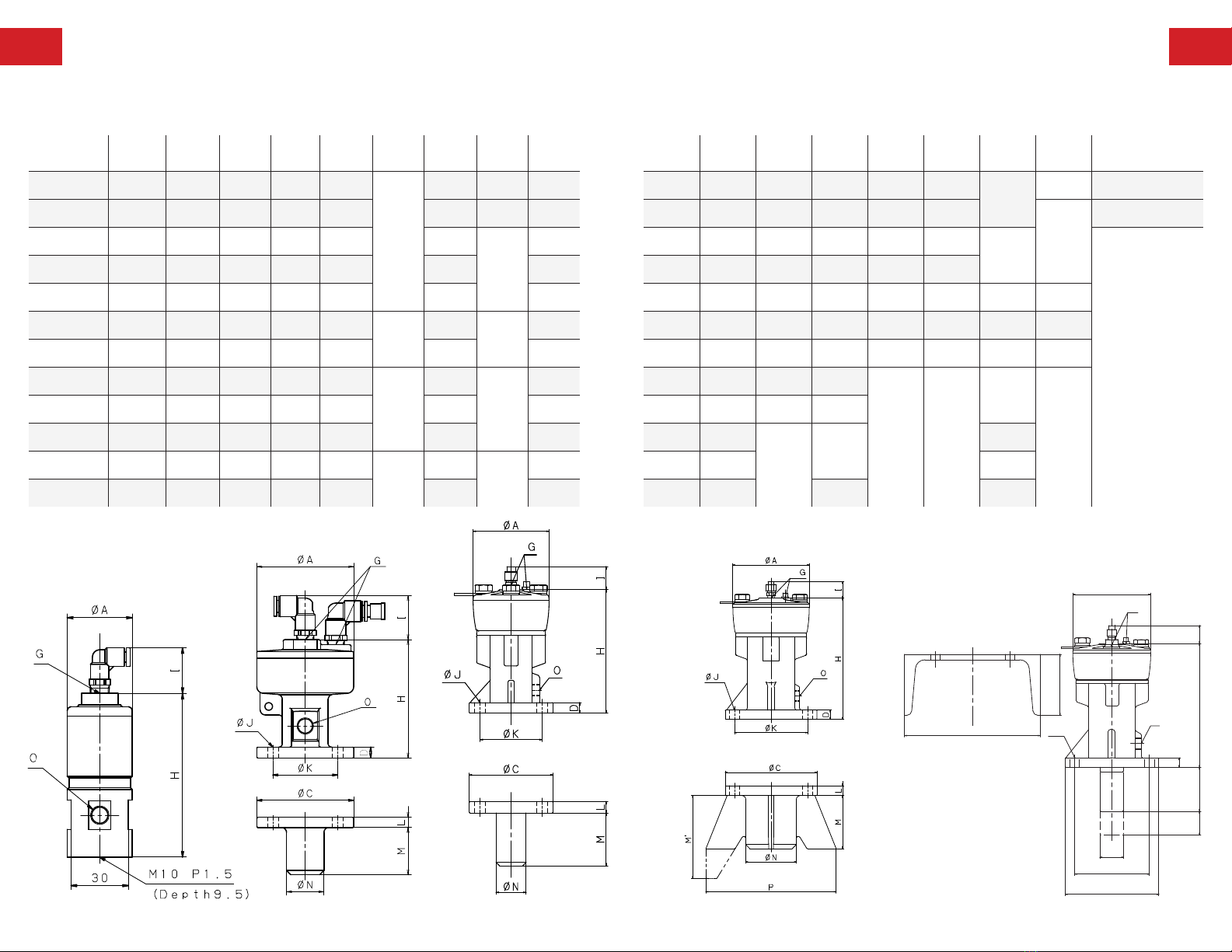
Dimensions
Model
(KNR-) ΦAΦCDΦEF G H I ΦJ
15-SS 1.34 –– –– –– ––
1/8”
NPT
3.39 (.94) ––
20 / 20-SS 2.25 2.25 0.25 - - 2.75 (1.02) 0.25
30 / 30-SS 2.59 2.75 0.31 - - 3.73
(0.98)
0.33
40 / 40-SS 3.39 3.73 0.47 - - 5.52 0.48
60 / 60-SS 4.53 5.44 0.55 - - 7.2 0.58
80 / 80-SS 5.75 5.83 0.63 - - 1/4”
NPT
8.73
(1.11)
0.67
100 6.89 8.19 0.78 - - 10.63 0.83
30-DI 2.59 2.75 0.31 0.59 1.5
1/8”
NPT
3.73
(0.98)
0.33
40-DI 3.39 3.73 0.47 0.92 2.17 5.52 0.48
60-DI 4.53 5.44 0.55 1.38 2.56 7.2 0.58
80-DI 5.75 5.83 0.63 1.88 2.36 1/4”
NPT
8.73
(1.11)
0.67
100-DI 6.89 8.19 0.78 2.14 1.97 10.63 0.83
F
L
ΦE
ΦC
M
ST
D
H I
G
ΦA
O
ΦJ
ΦK
F
L
ΦE
ΦC
M
ST
D
H I
G
ΦA
O
ΦJ
ΦK
ΦKST L M M" ΦNO W Tube Size
–– –– –– –– –– ––
1/8” NPT
–– Φ1/4 × Φ1/8
1.73 -0.23 1.11 -0.86
-
Φ1/4 × Φ1/8
2.17 -0.31 1.38 -1.09
1/4” NPT
Φ5/16 × Φ1/4
2.75 -0.52 2.36 -1.34
4.33 -0.59 3.16 4.72 33/8” NPT 7.72
4.72 -0.7 3.55 4.53 31/2” NPT 8.5
6.69 -0.91 4.53 5.31 4.5 3/4” NPT 12.13
2.17 0.67 1.97 3.94
- -
1/4” NPT
-
2.75 0.98 2.95 5 .91
4.33 1.38
3.55
7.88
3/8” NPT
4.72 1.58 1/2” NPT
6.69 1.97 9.84 3/4” NPT
M"
means curve
surface
dimension
KNR-15 Models KNR-20 Models
RKVS15
RKVS20
RKVS15
RKVS20
KNR-60/80/100 Models KNR- DI ModelsKNR-30 / KNR-40 Models
RKVS30・40
RKVS60
RKVS30・40
RKVS60
(inches)

Solimar Pneumatics | Minneapolis, MN 55432 USA | 1.800.233.7109 | P: 763.574.1820
Solimar, Solimar-USA and the Radial Ridge Design are trademarks of Solimar Pneumatics
Since 1985
This manual suits for next models
16
Table of contents
Popular Industrial Equipment manuals by other brands


Loepfe
Loepfe YarnMaster Zenit instruction manual

AVK
AVK 870 Series Installation, operation and maintenance manual

Seifert
Seifert 851200034-BZBG user manual

ABB
ABB HT574957 original operation manual

AGC
AGC ProFlow Pro3-XP Operation and maintenance manual

PCB Piezotronics
PCB Piezotronics J353B32 Installation and operating manual


