BobsCNC QUANTUM MINI User manual

Assembly Manual
Rev 1.0
MINI

1
Welcome to the Family.
We’re excited that you purchased the Quantum MINI CNC
Router Kit from BobsCNC, and we know you’re just as excited
to put it together. This manual gives you step by step
instructions to ensure your success in assembling the
Quantum MINI and provides all the information you need to
get your machine up and running.
Before beginning the assembly, take all the time you need to
completely review the manual. It’s good to be familiar with
the entire assembly process before diving in. Be sure to
check out the recommended tools you’ll need for the
assembly.
Welcome to the BobsCNC family. It’s time to… Unleash Your
Creativity!
Version 0.37

2
Contents
Information/Warning Boxes.........................................................................................................................5
Safety Precautions and Warnings..............................................................................................................6
Getting Started..................................................................................................................................................7
Required Tools:.............................................................................................................................................7
To Assemble the Quantum CNC Kit.....................................................................................................7
To Operate the BobsCNC Quantum CNC Router, you need will need:..................................7
Recommended for the electronic setup include: ............................................................................7
Assembly Recommendations: .....................................................................................................................8
Belt Drive.............................................................................................................................................................9
Wood Components (Included with Kit)...............................................................................................9
Required Hardware.....................................................................................................................................9
Illustrated Step by Step Instructions................................................................................................. 10
X Frame Instructions .................................................................................................................................... 16
Required Wood Components.............................................................................................................. 16
Required Hardware.................................................................................................................................. 17
Illustrated Step by Step Instructions................................................................................................. 17
Z Spindle Mount Assembly: ...................................................................................................................... 24
Required Wood Components.............................................................................................................. 24
Required Hardware.................................................................................................................................. 25
Illustrated Step by Step Instructions................................................................................................. 26
Y Carriage Assembly and Z Assembly................................................................................................... 38
Required Wood Components.............................................................................................................. 38
Required Hardware.................................................................................................................................. 39
Illustrated Step by Step Instructions ................................................................................................. 41
Gantry Assembly............................................................................................................................................ 59

3
Required Wood Components.............................................................................................................. 59
Required Hardware.................................................................................................................................. 60
Illustrated Step by Step Instructions................................................................................................. 61
Final Assembly................................................................................................................................................ 88
Required Wood Components.............................................................................................................. 88
Required Hardware.................................................................................................................................. 88
Illustrated Step by Step Instructions................................................................................................. 90
T-Slot Spoilboard ........................................................................................................................................125
Wood Components ...............................................................................................................................125
Required Hardware................................................................................................................................125
Illustrated Step by Step Instructions...............................................................................................125
Completed Views ........................................................................................................................................130
Tramming.......................................................................................................................................................132
Clamping System ........................................................................................................................................134
Wood Components (Included with Kit)..........................................................................................134
Required Hardware................................................................................................................................134
Congratulations! You Just Completed the Assembly of Your BobsCNC Quantum CNC
Router, Mini...................................................................................................................................................135
Appendix ........................................................................................................................................................136
Firmware Values......................................................................................................................................136
Quantum Washer Size Table..............................................................................................................137

4
BobsCNC Quantum Specifications
The assembled footprint:
Length: 38" (965 mm)
Width: 40" (1016 mm)
Height: 22" (559 mm)
Assembled Weight: 35 lbs.
Cutting Area:
X: 16" (407 mm)
Y: 16" (407 mm)
Z: 3.8" (98 mm)
Safety is always the First Priority. Always wear proper
protective equipment and use "safety sense" when
assembling and operating your Quantum Series CNC
Router.
5
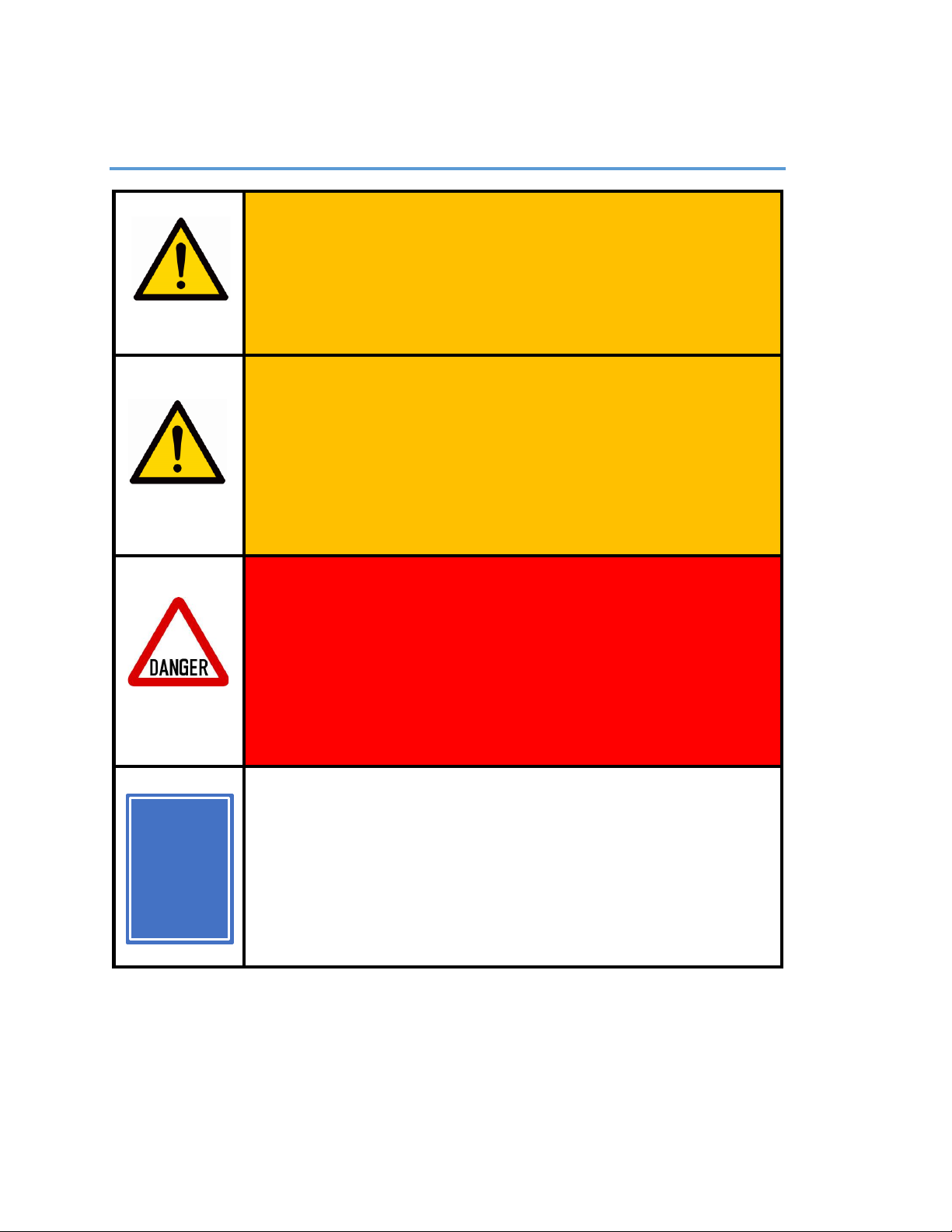
Information/Warning Boxes
CAUTION Indicates a possible risk of
injury that can result from failure to follow
this instruction
WARNING Indicates the possible
damage to the machine, its components,
the work piece, or injury that can result
from failure to follow this warning.
DANGER Indicates a serious risk of
bodily harm, injury and death. This is a
serious warning and should not be
ignored. Any work must be carried out
with extreme caution.
TIPs Contains helpful information,
shortcuts, and hints to simplify assembly
and make machine operation easier and
safer.
TIP
T

6
Safety Precautions and Warnings
BobsCNC Routers have a 110 v. Power Supply and use bits that spin at 30,000
rpm with cutting edges that are sharp and hazardous. The operator must
understand the potential hazards and is responsible to take appropriate
safety precautions before operating the Router.
•Only use extension cords rated for 20 amps plugged into a dedicated
outlet.
•Inspect the machine before every use for maintenance issues: loose
fasteners, belts, etc.
•Do not operate the machine with dull or damaged router bits.
•Always unplug machine after each use and when cleaning the router or
changing router bits.
•Remove rings, bracelets, watches, necklaces before using the machine.
•Wear snug fitting clothing and/or roll up long sleeves to prevent snagging.
•Use appropriate personal protective equipment (PPE) when operating
machine including safety glasses and hearing protection.
•Keep hands, hair, and clothing away from the moving parts of the
machine.
•Do not operate the machine when under the influence of alcohol or
prescription medications.
•Make certain the workpiece is clamped securely in place before starting
the machine.
•Never leave the machine running unattended.
•Children must be supervised by adults when operating the machine.
•Do not operate the machine in the presence of flammable materials.
•Keep floors clean, dry, and free of debris to eliminate slip and/or trip
hazards.
•Have a suitably rated fire extinguisher on hand when the machine is in
operation.

7
Getting Started
Required Tools:
To Assemble the Quantum CNC Kit
Metric Socket Set
#1, #2 and #3 Phillips Screw Drivers
Needle Nose Pliers
Set of Metric Allen Wrenches
Pliers
Utility Knife
Clear Nail Polish or Locktite™
Scissors
Blue Painter’s
Tape
To Operate the BobsCNC Quantum CNC Router, you need will need:
Computer with control software for GRBL.
Materials for Projects.
1/4” Shaft Router bits.
Recommended for the electronic setup include:
Multimeter to correctly connect the Power Supply and to set the
current for the Stepper Motors (a great tool for general electronic
trouble shooting).

8
Assembly Recommendations:
Use a large, flat, clean work surface for assembling your Quantum
Mini.
All Screws (unless noted) should be installed snug, then rotated 1-2
½ turns.
Apply LOCTITE™or clear fingernail polish to all M4 X 16 mm Machine
Screw that are used to secure plywood pieces. Machine Screws that
are secured with Lock Nuts do not need LOCTITE™.
Light sanding of the wood components may be performed if desired.
Painting or applying stain with a clear coat will provide extra
protection to the wood components.
Clean the rails with acetone to remove rust preventative and apply a
light coat of PTFE (Teflon®) lubricant.
We recommend using strips of 1-inch blue painters’ tape behind the
T-Slots to help hold the Nuts in place during assembly.
Lock Nuts are never used to secure components that have T-Slots.
They are only used to mount components where the Nut is not
held in a T-Slot.
CAUTION This kit contains numerous small
components that pose a choking risk for small
children and pets. Keep kit pieces in a secure
location out of the reach of small children and
pets.

9
Belt Drive
Wood Components (Included with Kit)
Part #
Description
Qty
Photo
QR2
XY Stepper Motor
Mount
3
Required Hardware
Part #
Description
Qty
Photo
H86
Flanged Bearing
F635Z
12
H48
M5 x 30 Machine
Screw
6
H49
M5 Lock Nut
6
H50
Idler Fender
Washer
12
H89
Small Black
Washer
12
H84
GT2 Pulleys
3
H37
M3 x 10
12
H88
M3 Washer
12
CB11
Stepper Motor
3

10
Illustrated Step by Step Instructions
Step 1 Preparing the Stepper Motors for Mounting
Step 1a Align one of the Set Screws of the GT2 Pulley
(H84) to the flat surface of the Stepper Motor
(CB11) Shaft. Snug the Set Screw so that it
engages the shaft but still allows the Drive
Pulley to slide down the shaft.
Flat Surface of Shaft
Set Screw

11
Step 1b Use an Idler Fender
Washer (H50) as a
shim and gently
slide the Drive Pully
down to the surface
of the Washer.
Fully tighten the Set
Screw against the
flat. Tighten the
second Set Screw.
Remove the Idler
Fender Washer. The
gap between the
bottom of the Drive
Pulley and the
Stepper Motor
housing will be approx. 1.25mm. Repeat for all three
Stepper Motors.

12
Step 2 Mounting the Stepper Motors
Step 2a Build four Idler Bearing Assemblies using
one (H48) M5 x 30 Machine Screw, two
(H86) Flanged Bearings, and two (H50)
Idler Fender Washers in the sequence
shown below.
Be sure the head of the Machine Screw
fits against the Bearing flange and the
other is mounted so that both flanges
are oriented outboard from each other.
Step 2b Insert the threaded shaft of Bearing
Assembly though the XY Stepper Motor
Mount (QR2) and secure with a M5 Lock
Nut (H49).

13
Repeat to install the remaining Idler
Assembly.
Step 2c Align the mounting holes of the Stepper
Motor with holes in the X, Y Stepper
Motor Assemblies.

14
Secure the Stepper Motor to the Stepper
Motor mount with four M3 x 10 Machine
Screws (H37) with M3 Washers (H88).
NOTE: When viewed from the back, the Stepper Motor wires of
each Motor are oriented in three directions. The wires of the Y
Stepper Motor are centered between the Flanged Bearing and
run upward. The wires of the X1 and X2 Stepper Motor wires run
one to the left, the other to the right as shown below.

15
NOTE: When properly installed, the flanges of the Flanged
Bearings will frame the teeth of the Drive Pulley (see below).
Drive Pulley
Flanges
16
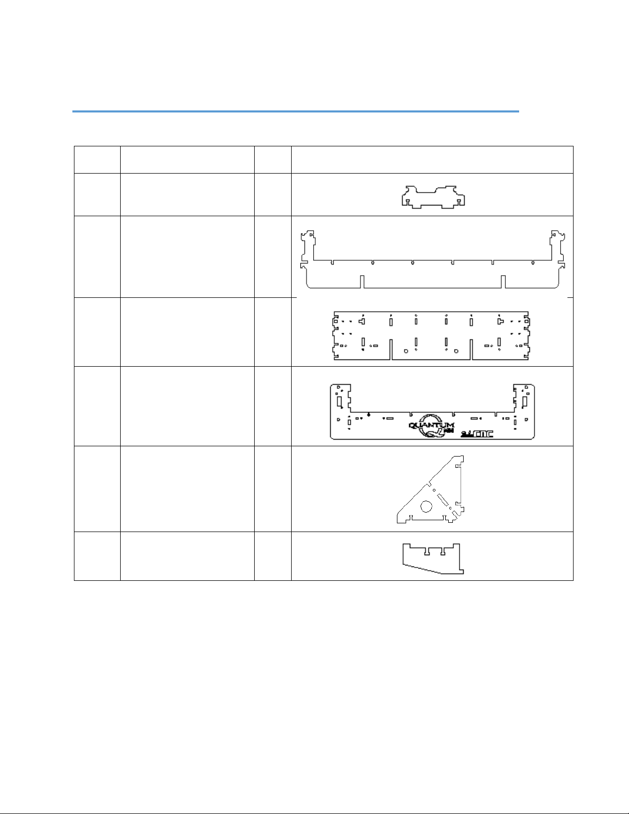
X Frame Instructions
Required Wood Components
Part #
Description
Qty
Photo
QX1M
Rail Support
8
QX4M
Frame Mid Support
2
QX5M
Frame Side Support
2
QX6M
Frame End Support
2
QX8
Frame Corner Support
4
QX11
Belt Support
4

17
Required Hardware
Part
#
Description
Qty
Photo
H14
M4 x 16 Machine
Screw
60
H15
M4 Nut
60
Illustrated Step by Step Instructions
Step 1 Build the Side Assemblies.
IMPORTANT: The long, open slots in the Frame Side
Support (QX5M) are oriented toward the bottom of
the X Frame Assembly.
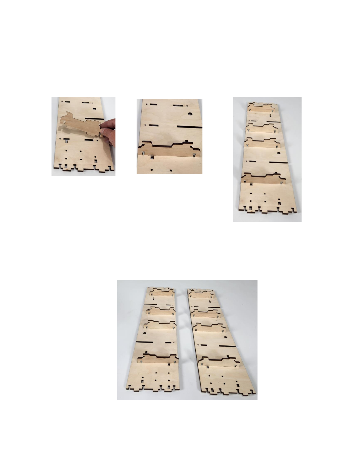
18
Step 1a Insert the tabs of four Rail Support (QX1M) in
the slots of the Frame Side Support (QX5M) and
secure each with two M4 x 16 Machine Screws (H14)
and Nuts (H15).
Step 1b Repeat to complete the other Side
Frame Support
19
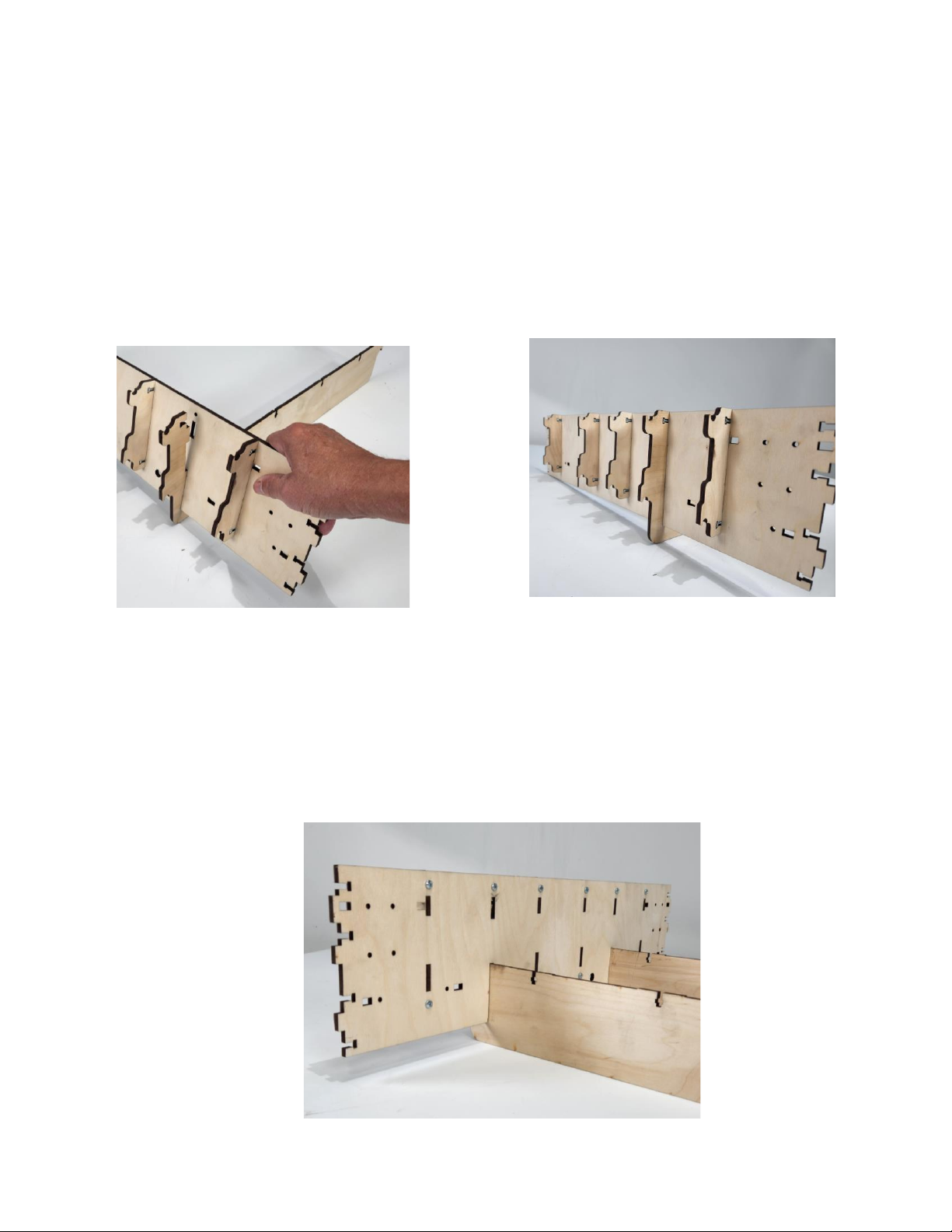
Step 2 Slide the open slot of the Frame Side over the Outer
Frame Mid Support (QX4M). Insert the tabs of the
Outer Frame Mid Support into the upper slot of the
Frame Side Support and secure with one M4 X 16
Machine Screw and Nut as shown.
Step 2a Repeat the steps to install the
second Outer Frame Mid Support
as shown.
This manual suits for next models
2
Table of contents
Other BobsCNC Industrial Equipment manuals


Popular Industrial Equipment manuals by other brands

Flowserve
Flowserve Limitorque Accutronix MX Maintenance & Spare Parts Manual

nosted
nosted Igland 42 owner's manual

Asco
Asco 5350 user guide

Walther prazision
Walther prazision 91489 Working Instruction

Siemens
Siemens RUGGEDCOM APE Series Configuration manual

ipf electronic
ipf electronic OT18 4 Series manual


