AGC ProFlow Pro3-XP User manual

AGC Model Pro3-XP
Operation and Maintenance Manual


Table of Contents
Scope:........................................................................................................................1
Receiving and Inspection:..........................................................................................1
Drawing Package:......................................................................................................2
Frame Placement:......................................................................................................3
Frame Connections:...................................................................................................5
Normal Operation:......................................................................................................6
Opening the Heat Exchanger:....................................................................................7
Operator Maintenance:...............................................................................................8
Parts List:...................................................................................................................9
Pro3-XP Frame Components............................................................................10
Pro3-XP Rail Size Chart....................................................................................11
Pro3-XP Tiebolt Assembly ................................................................................12
Pro3-XP Terminal Assembly.............................................................................13
Pro3 Plate and Frame Gaskets.........................................................................14
www.agcheattransfer.com
Western
3109 NE 230th Avenue
Fairview, OR 97024
+1.503.774.7342
++1.800.715.8820
FAX +1.503.774.2550
Central
8400 Lakeview Parkway
Suite 700
Pleasant Prairie, WI 53158
+1.847.301.6890
+1.888.489.8820
Eastern
10129 Piper Lane
Bristow, VA 20136
+1.703.257.1660
+1.800.825.8820
FAX +1.703.330.7940


1
Scope:
This manual is a supplement to the AGC Heat Transfer ProFlow plate heat exchanger manual. We
recommend you read the ProFlow manual first because it will provide you with a basic understanding of
plate heat exchangers and define the technical terms used in this document. The information provided
within this manual describes the installation, operation, and maintenance of the AGC Heat Transfer Pro3-
XP heat exchangers.
Please read this manual carefully before installing your heat exchanger. Pay particular attention to
the safety instructions and the initial startup procedures. Failure to follow all safety recommendations could
result in injury to the operator or cause damage to the heat exchanger.
Receiving and Inspection:
Each AGC heat exchanger is assembled and fully tested at the factory prior to shipping. Once the
unit has successfully passed all tests it is prepared for shipping. Every AGC heat exchanger is thoroughly
inspected to ensure it is in perfect condition before leaving the factory. Upon arrival, carefully inspect your
new heat exchanger for any damage that may have occurred during shipping. If the press was damaged
during shipping make sure it is annotated on the shipping documents. Also, report any damage to AGC
immediately. To aid you in describing where any damage may have occurred, figure one shows the major
components of a typical Pro3 frame with one terminal.
Figure 1
Major Frame Components

2
Normally, Pro3-XP frames are shipped with the plates installed. As a result the press and plates
can weigh several thousand pounds. We recommend only qualified forklift operators should lift and
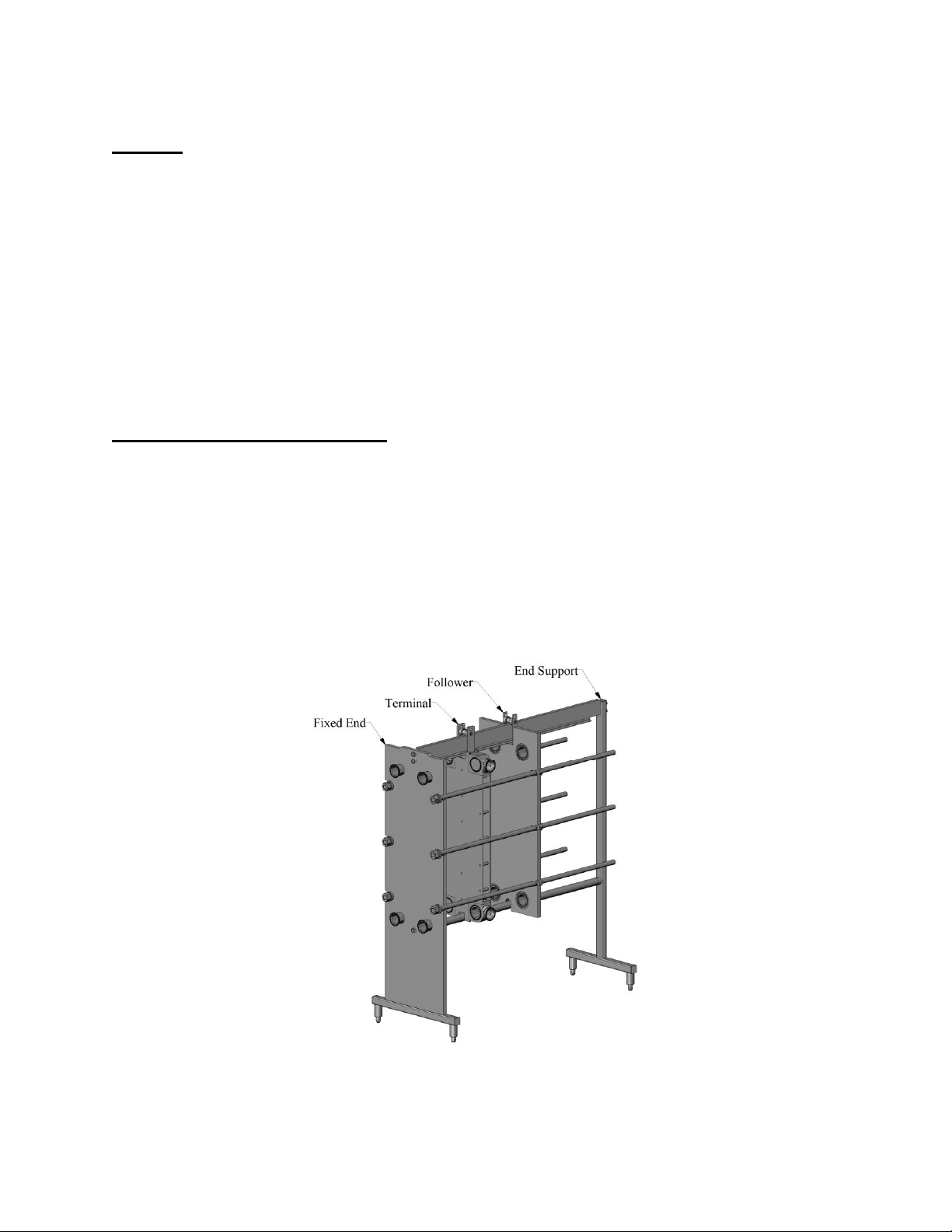
position the unit. It should be noted that the high leg frame, also known as the Pro3-XPH, can be top heavy
and could tip if they are not moved properly.
Drawing Package:
Every frame is shipped with a drawing package. This drawing package contains important
information that is specific to your heat exchanger. If you cannot find the drawing package, contact AGC
Heat Transfer or your local AGC distributor to obtain a replacement prior to installing the heat exchanger.
The drawing package is a collection of several important documents related explicitly to your heat
exchanger. The first of these is the streaming diagram. Two copies of the streaming diagram are included.
One copy has been laminated to protect it. This copy is intended to be used by production and maintenance
personnel when installing and/or servicing the heat exchanger. The remaining copy should be kept on file
in a safe place in the event the production copy is lost or damaged. The streaming diagram (also referred
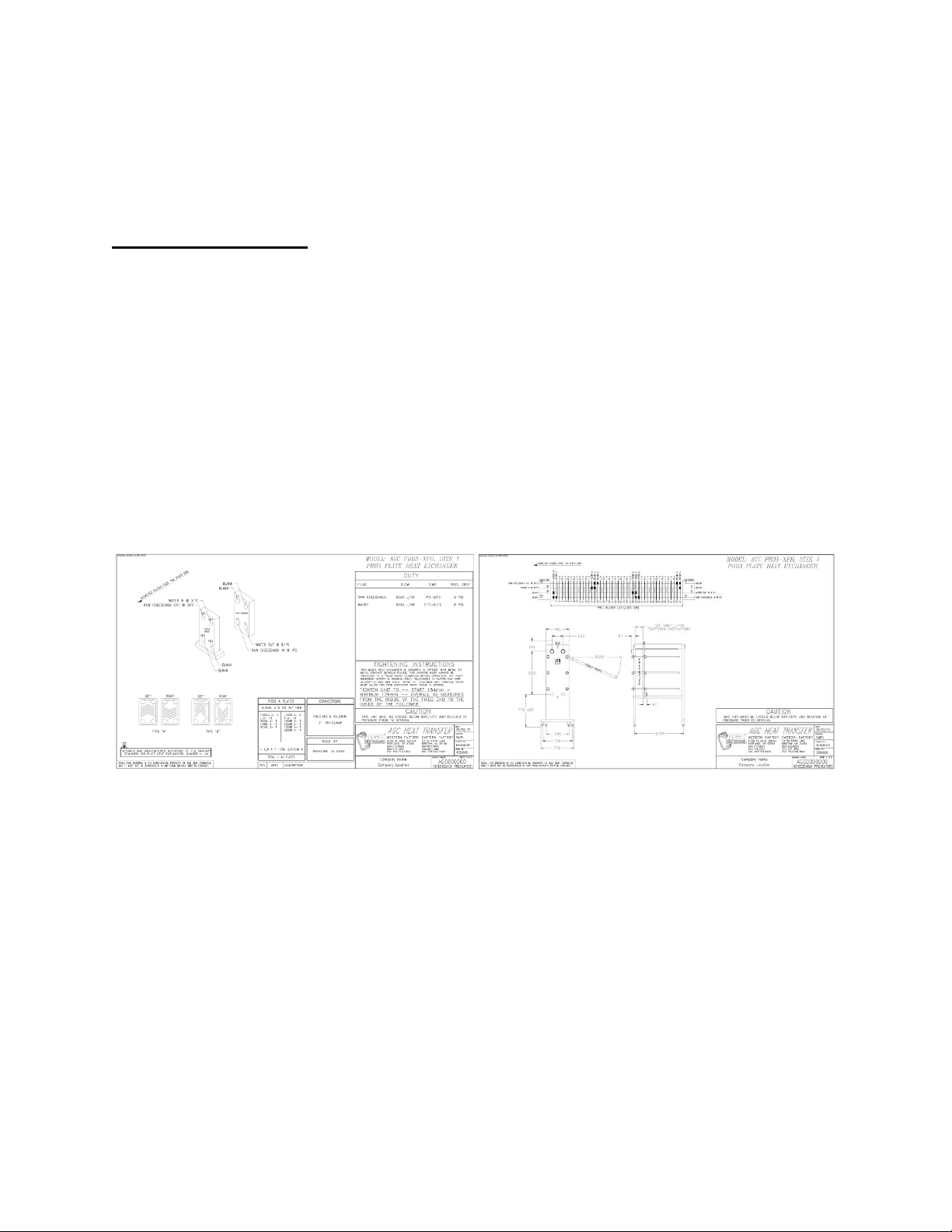
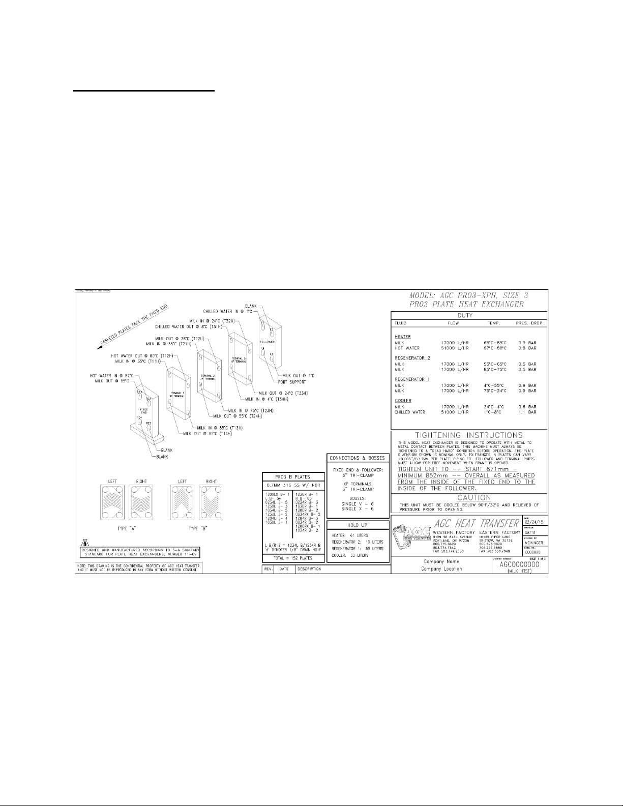
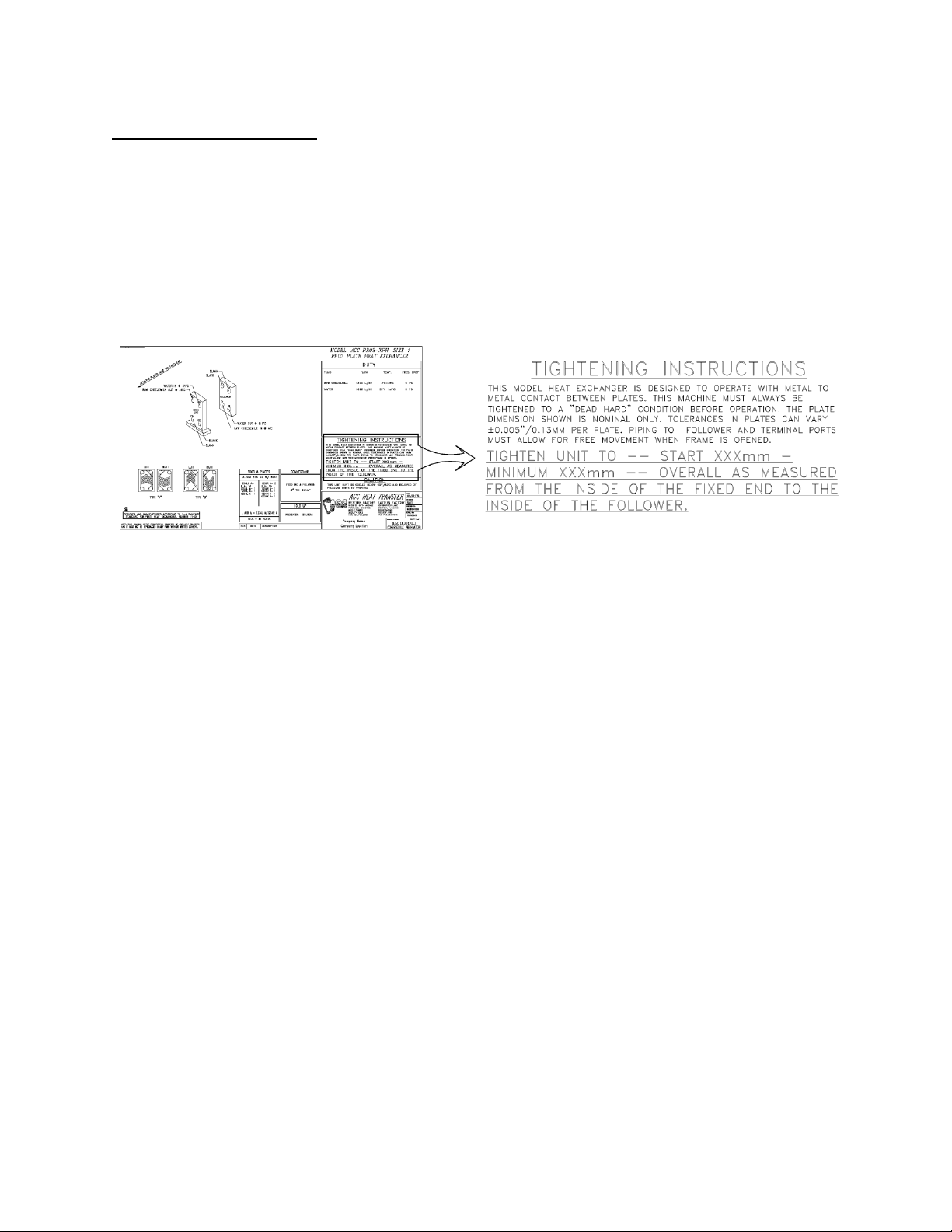
to as the drawing) describes all the characteristics of the heat exchanger. Figure 2 shows a typical two page
streaming diagram.
Figure 2
Typical Streaming Diagram
Page one shows the unit serial number, the duty, plate type, plate count, gasket type, connection
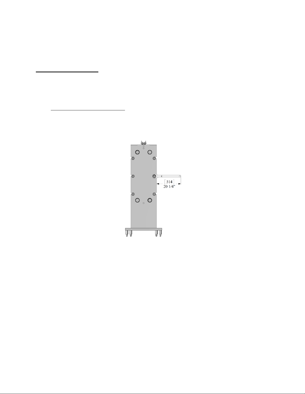
type, connection size, and the tightening dimension. Revisions are also listed on page one. Page two of
the drawing shows how the fluids pass through the heat exchanger. (The ProFlow manual describes how
to read this flow diagram). If the unit is small, such as the unit in figure two, a front and side view of the
heat exchanger will be shown as well. For larger units the front and side views are shown on page three or
page four.
The second document in the drawing package is a plate punching diagram. This diagram will show
you how to identify each Pro3 plate either by its configuration number (stamped at the top of each plate) or
by looking at the plate noting which ports have been opened. Since the Pro3 plate is a vertical flow plate,
each plate can be used for either a right or left hand plate. The ProFlow manual explains how these plates
are used in greater detail.

3
The final document in the drawing package is the ProFlow manual. The ProFlow manual has
information about the AGC Heat Transfer product line and a more in-depth discussion about plate heat
exchangers in general.
Frame Placement:
Locate the Pro3-XP frame on a firm flat surface capable of supporting the press and all of its
contents when full. If possible, the frame should remain strapped to the shipping skid until it is near its
final location. Once the press is positioned cut the metal bands holding it to the shipping skid and, using
an appropriately sized lifting strap, carefully lift the press off the skid. The top rail can be used as a lifting
point. Never lift the pressby the tiebolts. These bolts are in slots and are not designed to support the weight
of the frame for lifting. When locating the heat exchanger, ensure that adequate space is left around the
frame for maintenance and for plate installation/removal. Also include enough space to allow the AGC Fat
Boy™wrench to fully swing. See figure 3.
Figure 3
Wrench Space Requirement
The Pro3-XP and Pro3-XPH frames are equipped with adjustable ball feet. These feet are adjusted
by turning the base clockwise to lower and counterclockwise to raise the press. The ball feet should be
adjusted so the ports are level from side to side. Figure 4 shows a spirit level placed across the ports to
establish level.

4
Figure 4
Port Leveling
Once the ports are level, the heat exchanger should be adjusted so it will drain properly. This is
done by adjusting the ball feet to establish a slope from end to end. Figure 5 shows a press adjusted to drain
forward to the fixed end.
Figure 5
Frame Adjusted to Drain to Fixed End
Consult your onsite Plant Engineer or Project Manager to determine how much slope and which
direction (toward the fixed end or follower) is appropriate for your installation.

5
Frame Connections:
Careful planning during the installation of your new heat exchanger will help ensure years of
trouble free operation. All piping connections should be well supported and carefully aligned with the ports
on the heat exchanger. Misaligned pipes or pipes that are not properly supported can lead to connection
failures or cracks in the welded joints. When laying out a new installation, include enough breaks in the
piping so service and maintenance can be completed easily. The piping connected to the follower should
be configured with joints that are easy to remove so the follower can be fully retracted. This will provide
enough space for clear inspection of the heat exchanger plates. The streaming diagram will show where all
external connections should be made. Figure 6 shows page one of a typical streaming diagram for a multi
section heat exchanger.
Figure 6
Typical Streaming Diagram
Notice that all ports have labels that clearly state what is to be connected to each one.

6
Normal Operation:
The Pro3-XP series heat exchangers are tiebolt style frames. This means the press is closed by
using 6 tiebolts to compress the plates. For this type of frame it is important for each tiebolt to take an
equal share of the load. After your heat exchanger is in place you should check the compressed dimension
if the plates were shipped installed. The dimension for your heat exchanger is listed on the first page of
your streaming diagram. Figure 7 shows where the tightening dimension is located on the drawing. If the
plates were shipped in a separate crate refer to the ProFlow manual for instructions on installing them.
Figure 7
Tightening Instructions
Most new plate packs will seal at the start dimension. As the plates and gaskets wear it may be
necessary to compress or close the press further. You should never exceed the minimum dimension shown
on the streaming diagram. If your press is closed to the minimum dimension and leaks are noticed contact
AGC Heat Transfer for technical assistance. Closing the press beyond the minimum dimension could cause
permanent damage to the plates, frame, or both. When measuring the compressed dimension it is a good
practice to take the measurement in several locations on the inside of the fixed end and follower as shown
in figure 8.

7
Figure 8
Tightening Location and Sequence
Measure top and bottom as well as front and back. The heat exchanger is designed operate at its
top efficiency when it is closed to a metal to metal condition. This means the rubber plate gaskets are fully
compressed and the plates contact points are fully engaged with each adjacent plate. In this condition, the
plate gap is uniform and the plate is fully supported. To maintain this condition all tiebolts should be
tightened equally and in sequence. Following the sequence shown in figure 8, tighten each tiebolt in small
increments so the follower remains parallel to the fixed end. As the press approaches the start dimension
smaller increments at each bolt will make for easier closing.
After the press is closed and all connections are made to the heat exchanger the unit is ready to be
pressure checked. Consult the onsite plant engineer or project manager for the correct procedure on
pressure testing the press.
Opening the Heat Exchanger:
Before opening this or any other heat exchanger you must verify the temperature in the unit is
below 90° F and that the unit has been relieved of all internal pressure. Failureto follow this safety warning
could result in serious injury to the operator or damage to the plates and gaskets. All pipes/connections
should be disconnected from the heat exchanger before the tiebolts are loosened.
Prior to opening the press, inspect the tiebolts to ensure they are free from dirt or excessive dust
and that lubrication is present on each. Opening or closing the tiebolts without lubrication may cause
permanent damage to the tiebolt. Small increments on each bolt will make the process easier and prevent

8
damage to the press or any of its parts. The tiebolts should be loosened using the same sequence as for
tightening. See figure 8 for the bolt sequence. As with tightening, the closer the unit is to the minimum
dimension the more torque will be required on the Fat BoyTM wrench. Once the plates are completely
uncompressed, the tiebolts can be lifted from their slot. Handle the tiebolts with care so the threads are not
damaged. The follower can now be moved back toward the end support and the plates can be inspected or
removed.
Operator Maintenance:
All AGC Heat Transfer heat exchangers are designed to require minimal operator maintenance. As
long as the unit is operated within the pressure and temperature limits the only maintenance required is
routine cleaning, lubrication and inspection. We recommend the unit be leak checked annually using the
PlateCheckTM field service provided by AGC Heat Transfer. This service is performed onsite by factory
trained service engineers. The PlateCheckTM service provides a thorough inspection of all parts of the heat
exchanger. After the service is complete, a detailed written report is provided on the condition of the heat
exchanger. This preventative maintenance service greatly reduces unscheduled down time by keeping the
heat exchanger in peak operating condition.

9
Parts List:
Replacement parts for any AGC Pro3-XP frame can be ordered from AGC Heat Transfer or from
your local AGC Distributor. Most parts are in stock and can be shipped within 24 hours from the time we
receive your order. Some parts have been revised so it is important to have your unit model and serial
number available when placing an order for spare or replacement parts. Most of the field replaceable parts
are listed in this manual. If the part you need is not listed on the following pages contact your local AGC
distributor or the AGC Heat Transfer Factory.
Contact information is provided below or visit our website for more information:
www.AGCHeatTransfer.com
Western
3109 NE 230th Avenue
Fairview, OR 97024
+1.503.774.7342
++1.800.715.8820
FAX +1.503.774.2550
Central
8400 Lakeview Parkway
Suite 700
Pleasant Prairie, WI 53158
+1.847.301.6890
+1.888.489.8820
Eastern
10129 Piper Lane
Bristow, VA 20136
+1.703.257.1660
+1.800.825.8820
FAX +1.703.330.7940

10
Pro3-XP Frame Components
*Note: All rails shipped without bolts and washers unless specifically ordered.
Item
Quantity
Part Number
Description
1
1
11012310
Pro3-XP Fixed End
2
1
See Chart
Pro3-XP Upper Rail
3
1
See Chart
Pro3-XP Bottom Rail
4
1
11012330
Pro3-XP Follower
5
1
11012340
Pro3-XPH End Support
6
6
See Chart
Pro3-XP Tie Bolt Assembly

11
Rail Size
Rail Length
Upper Rail Part Number
Lower Rail Part Number
1
1118 [44”]
11012365
11014700
2
1701 [67”]
11012366
11014703
3
2311 [92”]
11012367
11014704
4
2921 [115”]
11012368
11014705
Pro3-XP Rail Size Chart

12
Item
Quantity
Part Number
Description
1
1
See Chart
Tie Bolt Base
2
1
SG114C
Bronze Nut
3
1
11013002
Thrust Washer
4
1
EW203202
Thrust Bearing
5
2
11012377
Pro3-XP Tie Bolt Bushing
Pro3-XP Tie Bolt Size Chart
Tie Bolt Size
Overall Length
Tie Bolt Base Part Number
Complete Assembly Number
1
1118 [44”]
11012374
11012370
2
1701 [67”]
11012375
11012371
3
2311 [91”]
11012376
11012372
4
2921 [115”]
11012377
11012373
Note: To order a complete tiebolt assembly use assembly number for desired size.
Pro3-XP Tiebolt Assembly

13
Pro3-XP Terminal Parts
Description
Part Number
Pro3-XP Terminal without Roller
11012350
Pro3-XP Terminal Roller with Pin
11012335
Pro3 Port Boss V Configuration
11018516
Pro3 Port Boss X Configuration
11018515
Pro3 Port Boss with 2” Pressure Switch
11018518
Pro3 Port Boss Blank
11018520
Pro3 Port Boss Thru
11018513
*Note: Port Bosses shown with tri-clamp ferrules. Other connections are available on request.
Pro3-XP Terminal Assembly
(All Pro3 Tiebolt Frames)

14
Pro3 Plate and Frame Gaskets


rest"™
TM
Western
3109 NE 230th Avenue
Fairview, OR 97024
+1.503.774.7342
+1.800.715.8820
FAX +1.503.774.2550
Central
8400 Lakeview Parkway
Suite 700
Pleasant Prairie, WI 53158
+1.847.301.6890
+1.888.489.8820
Eastern
10129 Piper Lane
Bristow, VA 20136
+1.703.257.1660
+1.800.825.8820
FAX +1.703.330.7940
Table of contents
Other AGC Industrial Equipment manuals