SDI-12 User Guide for AquaVent
Page 7
2 AquaVent Independent Recording Option
The AquaVent logger has the ability to record and store readings in its internal
memory, independent from the SDI-12 network, while connected to an SDI-12
master. Before connecting the AquaVent to the SDI-12 master, it can be
programmed and started using Solinst Levelogger PC Software (see Figure 3-1).
All standard sampling options provided by Solinst Levelogger PC Software are
available while the AquaVent is operating as an SDI-12 sensor. The AquaVent
logger can be set to record at a user-defined sampling rate; event, linear, and
scheduled sampling modes are available. This allows the AquaVent logger to
provide back-up data if the SDI-12 network fails. The AquaVent logger stores
the data in its internal memory, until it is downloaded.
If you program the AquaVent logger at a similar interval to the SDI-12 recorder,
it may require an occasional measurement retry by the recorder if the AquaVent
happens to be busy at that moment. You can change the schedule of either to
ensure this does not happen.
Each time the SDI-12 master asks the AquaVent for a current reading, the
Wellhead batteries are used to transmit the information from the logger to the
Wellhead. The AquaVent logger will also be using the batteries if programmed
to record independently – draining the batteries more quickly.
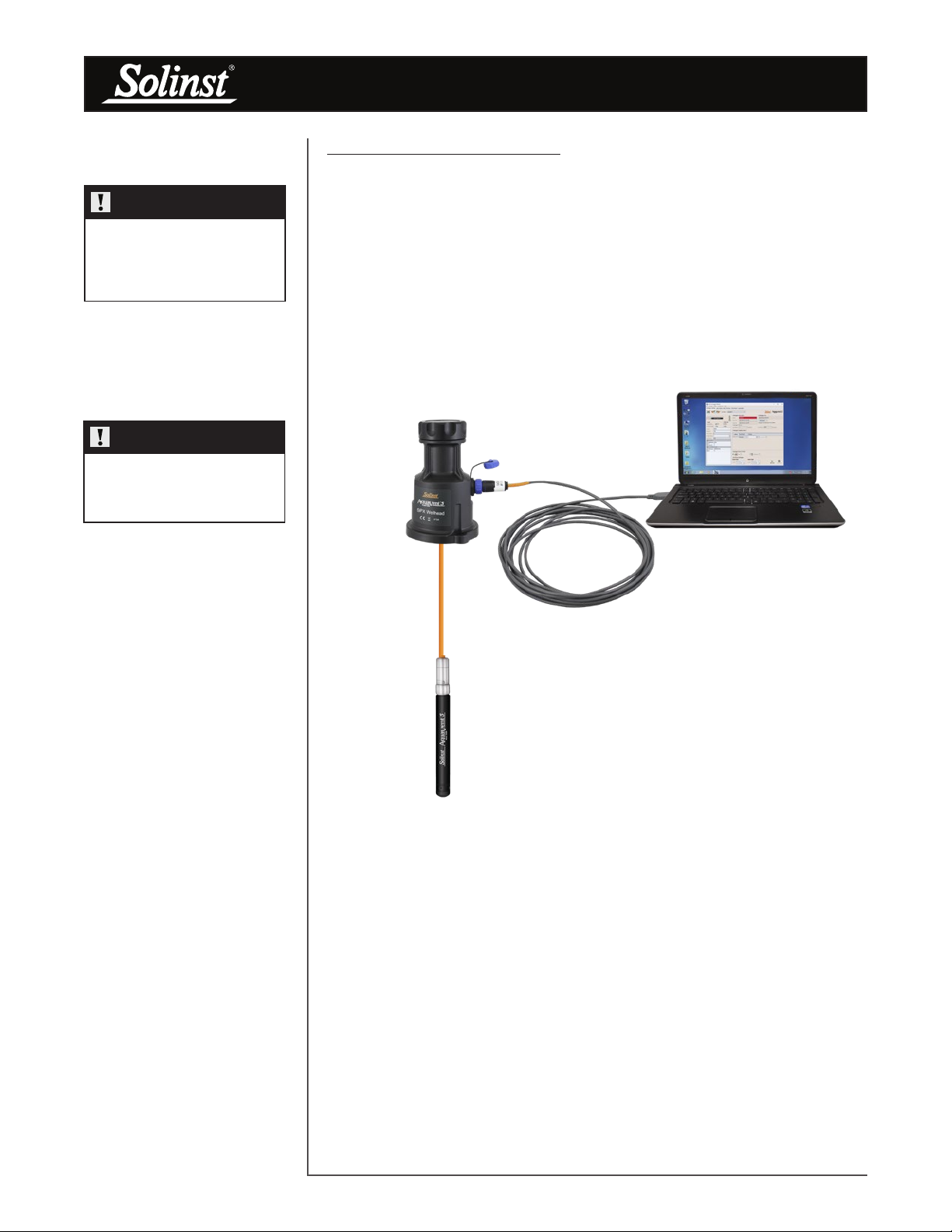
2.1 Data Downloading and Programming in Field
If the AquaVent logger has been programmed to record on its own independent
schedule, data can be downloaded from the AquaVent using a laptop and
USB Connector Cable in the field (see Figure 3-1). Temporarily disconnect the
AquaVent from the SDI-12 Connector Cable, preferably in between recordings
by the SDI-12 master. Connect a laptop and download the independently
recorded data.
If the AquaVent is disconnected from the SDI-12 network, and the SDI-12
master tries to communicate with the AquaVent, the SDI-12 master and the rest
of the sensors in the network are not disrupted.
After the data download is complete, the AquaVent is easily connected back into
the SDI-12 network without disruption. The AquaVent is automatically verified
when reconnected (see Section 4.2).
NOTE
See the Vented Dataloggers User
Guide for detailed AquaVent
operating instructions.
NOTE
Once you are finished
programming your AquaVent,
unplug the USB Connector Cable
from the Wellhead. The Wellhead
only communicates with the SDI-
12 network when just the SDI-12
Connector Cable is connected.
NOTE
The Wellhead batteries will drain
more quickly if the AquaVent logger
is also set to record independently.
NOTE
Other downloading options
are available using the Solinst
Levelogger App and DataGrabber.
See separate operating instructions.