When possible, recharge your batteries when they about 50% discharged or earlier. This
gives the batteries a much longer life cycle than recharging when they are more deeply
discharged.
Our inverter has a battery low voltage shutdown around 20Vdc.With moderate to heavy
loads, this will protect against over-discharging the battery. if the inverter is running only
light loads it is advisable to recharge before the inverter low voltage shutdown point is
reached.
For more information on maintaining batteries, consult your battery's manufacturer.
For information about our battery chargers, please contact us.
The battery s back up time depends on the battery capacity(Ah)and your appliances
power (Watt)
The method to calculate the operation time is :
Battery capacity(Ah) x input back up / loads power(W)
For example:
Battery capacity= 150Ah
Input Voltage= 12V
Loading power= 600W
(150Ah x 12V)/600W= 3H
This section describes the most common problems you may encounter with the operation
of the inverter along with resolutions.
If you encounter problems other than what is described in this section, contact customer
supporting center.
16.1 COMMON PROBLEMS
16.1.1 Buzz in Audio Equipment
Some inexpensive stereo systems may emit a buzzing noise from their loudspeakers when
operated from the inverter. This occurs because the power supply in the audio System
does not adequately filter the modified sine wave produced by the inverter.
The only solution is to use a sound system that has a high quality power supply.
16.1.2 Television Reception
When the inverter is operating, it can interfere with television reception on some
channels. If interference occurs, try the following:
14.RECHARGING BATTERIES
15. BATTERY’S CAPACITY CALCULATION
16.TROUBLE SHOOTING
1. Make sure that the chassis ground screw on the rear of the inverter is solidly connected
to the ground system of your vehicle or home.
2. Make sure that the television antenna provides an adequate ( snow-free ) signal and
that you are using good quality cable between the antenna and the television.
3. Keep the cables between the battery and the inverter as short as possible, and twist
them together with two to three twists per foot. ( this minimizes radiated interference
from the cables.)
Move the television as far away from the inverter as possible.
Do not operate high power loads with the inverter when the television is on.
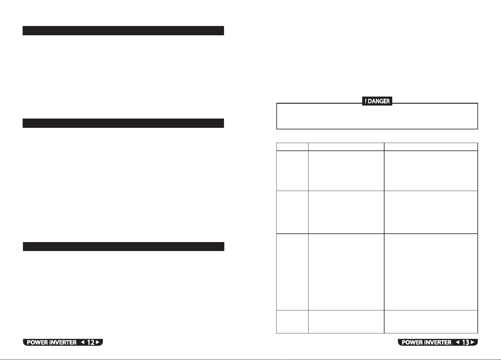
ELECTRICAL SHOCK HAZARD
Do not disassemble the inverter. It does not contain any user-serviceable parts.
Failure to follow these instructions can result in death or serious injury.
Problem Possible Cause Solution
Low output
voltage
No output
voltage.
Both the
power
light and fault
light are off
No output
voltage.
Fault light
is on
Low battery
alarm stays on
Poor DC wiring, Low battery poor
battery condition
Low input voltage
High input voltage
Thermal shutdown
Unit overload
Output is short circuited
The inverter is off.
No power to the inverter.
The inverter could have been
connected with reverse DC input
polarity
You are using a voltmeter that
cannot accurately read the RMS
voltage of a modified sine wave.
Low input voltage and the load is
close to maximum allowable power
Use a true RMS reading voltmeter such as
the Fluke87.
Check the connections and cable to see if
the battery is fully charged.
Recharge the battery if it is low.
Reduce the load.
Recharge the battery, check the connections
and cable. Make sure the
inverter is connected to a correct battery
(24V inverter for 24V batteries bank) Allow
the unit to cool off. Reduce the load if
continuous operation is required. Improve
ventilation. Make sure the inverter s
ventilation openings are not obstructed.
Reduce the ambient temperature. Reduce
the load. Make sure the load does not
exceed the inverter s output rating.
Remove the short circuit
Turn the inverter on.
Check the wiring to the inverter and to
the battery selector switch (if installed).
The inverter has probably been damaged.
Return the unit, damage caused by reverse
polarity is not covered by the warranty
Use proper cable size and lengths and make
solid connections
Charge the battery Install a new battery
16. 2 TABLE 1 TROUBLESHOOTING REFERENCE