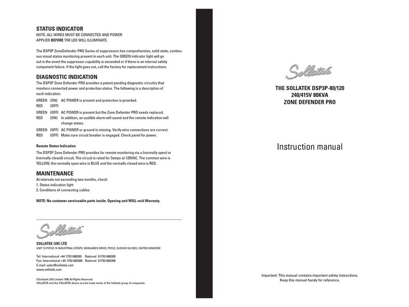
Sollatek DSP-D User manual

THE SOLLATEK DISTRIBUTION SURGE PROTECTOR
DSP-D, DSP-S, DSP-M RANGE
AC Panel Transient Voltage Surge Suppressors
INSTRUCTION MANUAL
Important: This manual contains important safety instructions.
Keep this manual handy for reference.
TM
DSP-M
THREE PHASE
DSP-S
THREE/SINGLE PHASE
DSP-D
THREE PHASE
THREE PHASE

2
Without doubt, power interruptions cause major problems for home and business
computing. An unpredictable power supply can lead to worrying problems such as
surges, spikes, lightning strikes, brown-outs, power-cuts (black-outs), power-back
surges, mains over-voltage, and complete failure - all of which can damage electrical
and electronic equipment. If any of these should occur, there’s a strong chance you
will suffer
from loss of critical data, lowered productivity and even damage to your
expensive equipment.
Sollatek encompasses a wide range of power protection products for use in many
different industries where clean, regulated mains power is critical to their continued
operation.
For more information on our range of power protection products, contact us now.
SOLLATEK (UK) LTD
UNIT 10 POYLE 14 INDUSTRIAL ESTATE,
NEWLANDS DRIVE, POYLE,
SLOUGH SL3 0DX,
UNITED KINGDOM
Tel: International +44 1753 688300 National 01753 688300
Fax: International +44 1753 685306 National 01753 685306
E-mail: [email protected]
www.sollatek.com
TM
The
DSP-D
range offers high capacity protection in industrial applications, ten-mode
protection and a max surge handling capabilities of 80kA, 120kA or 160kA per phase.
Ensuring protection at distribution boards, lighting systems and equipment panels and
cabinets. Featuring; solid-state diagnostics, LED indication of protection level status,
IP66 and UL 1449 rated. International three phase supply versions only.
The
DSP-S
range with ten-mode protection, maximum surge handling capacity of 90kA
per phase, when used in conjunction with a Sollatek DSP-M series at the main service
entrance provides the ultimate in complete high-capacity surge suppression. Requiring
no operator intervention, LED indicators allow each MOV network to be constantly
monitored. Remote monitoring by means of normally closed contacts. IP66 and UL 1449
approved. Single / three phase versions for all international supply voltages.
Designed for main service entrance locations, the
DSP-M
range gives ten-mode
protection, surge max surge current of 150kA or 180kA per phase. Visual or remote
warning alerts the operator of varistor network failure while a redundant unit keeps
protecting the site, even after a direct strike. Silicon avalanche diode versions are
available (DSP-150-SD) incorporating both SAD and MOV technology for a lower limiting
voltage. Remote monitoring by means of normally closed contacts. IP66 and UL 1449
approved. Three phase versions for all international supply voltages.
Contents
Sollatek DSP-D Series
p.3
Sollatek DSP-S Series
p.4
Sollatek DSP-M Series
p.6
Power problems p.10
Comparison chart p.11
THE SOLLATEK DISTRIBUTION SURGE PROTECTOR (DSP)
INTRODUCTION

3
SOLLATEK DSP-D SERIES
SOLLATEK DSP-D SERIES
AC Panel Transient Voltage Surge Suppressors
AC Panel Transient Voltage Surge Suppressors
INTRODUCTION
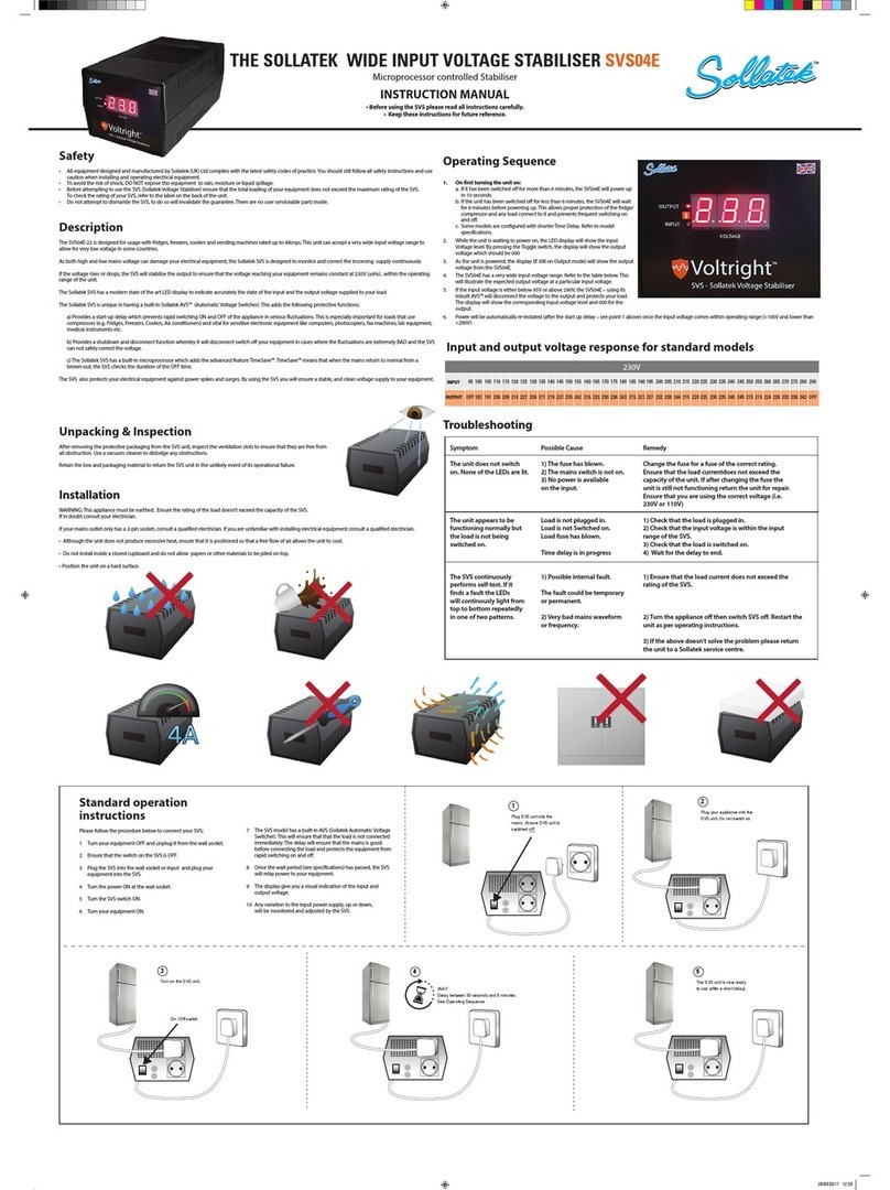
This document explains how to install the Sollatek DSP-D Series of AC Panel Surge
Protective Devices.
INSTALLATION INSTRUCTIONS
The suppressor should be mounted on or near the panel as close as possible to the
wire connection point. The suppressor has three mounting possibilities: surface, fl ush
or close nipple. In all three mounting possibilities connect the BLACK #12 AWG solid
wires to the phase conductors, connect the WHITE #12 AWG solid wire to the neutral
bus and connect the GREEN #12 AWG solid wire to the ground bus. At the installation
stage, cut each conductor AS SHORT AS POSSIBLE. Avoid large loops of wire and
sharp bends in the wires. Bind all connecting cables tightly together throughout the
wire run from the Sollatek DSP-D to the panel.
MOUNTING
Close Nipple Mounting:
Choose a location on the panel that will give the most direct connection to the phase
conductors and neutral-ground busses. Use a pre-existing ½ inch conduit knock-
out or drill a new ½ inch conduit hole in the panel. Remove the conduit nut from the
Sollatek DSP-D and slide the wires and conduit nipple into the panel. Reconnect the
conduit nut to the Sollatek DSP-D.
CAUTION: the conduit connection is plastic, DO NOT OVER-TIGHTEN. Connect wires
as described above.
Surface Mounting:
Choose a location near the panel that will give the most direct connection to the phase
conductors and neutral-ground busses. Use a pre-existing ½” conduit knock-out or
drill a new ½” conduit hole in the panel. Remove the conduit nut from the Sollatek DSP-
D Series and slide the wires and conduit nipple into the panel. A short piece (less than
3”) of plastic conduit may have to be added to the Sollatek DSP-D. Connect either the
close nipple on the Sollatek DSP-D or the short additional piece of conduit to the panel.
Use the four 0.20” mounting holes on the Sollatek DSP-D Series and secure it to the
wall using appropriate hardware (not supplied). Connect wires as described above.
Flush Mounting:
The fl ush mount Sollatek DSP-D Series is installed into a suitably sized hole in the wall.
This hole needs to be large enough for the body of the suppressor, yet not exceed the
fl ush mount plate mounting holes. Choose a location near the panel that will give the
most direct connection to the phase conductors and neutral-ground busses. Use a
pre-existing ½” conduit knock-out or drill a new ½” conduit hole in the panel. Remove
the conduit nut from the Sollatek DSP-D Series and slide the wires and conduit nipple
into the panel. A short piece (less than 3”) of plastic conduit may have to be added
to the Sollatek DSP-D Series. Connect either the close nipple on the Sollatek DSP-D
Series or the short additional piece of conduit to the panel. Use the four mounting holes
on the Sollatek DSP-D Series fl ush plate and secure it to the wall using appropriate
hardware (not supplied). Connect wires as described above.
INCORRECT INSTALLATION WILL IMPAIR THE EFFECTIVENESS OF AC PANEL SURGE
PROTECTORS. Particularly important is the length and routing of the connecting
leads.
STATUS INDICATOR
NOTE: ALL WIRES MUST BE CONNECTED AND POWER APPLIED BEFORE THE LED
WILL ILLUMINATE.
The Sollatek DSP-D Series of suppressors has comprehensive, solid state, continuous
visual status monitoring present in each unit. The GREEN indicator light will go out
in the event the suppressor capability is exceeded or if there is an internal safety
component failure. If the light goes out, call the factory for replacement instructions.
Panel LED Mount Models only:
Specifi c Sollatek DSP-D Series models have the
capability of panel indication. Drill a 0.280” hole in the panel in the desired location.
Maximum panel thickness is 0.125”. Remove the lens from the LED holder and snap
it into the panel. While holding the lens in place, snap the LED holder onto the lens.
Use the supplied wire nut to connect the wires, matching the color codes on the
suppressor to those on the LED holder.
REMOTE STATUS INDICATION
Each Sollatek DSP-D Series has remote indication of the protector status. This is
available as a normally closed dry contact. To utilize this feature, connections are
made to the pair of stranded RED #18AWG wires. If this loop opens, it indicates a
failure of the Sollatek DSP-D Series. Call the factory for replacement instructions. If
remote indication is not used, RED wires can be cut and taped off.
MAINTENANCE
At intervals not exceeding two months, check:
1. Status indication lights
2. Conditions of connecting cables and terminals
NOTE: No customer serviceable parts inside. Opening module WILL void warranty
CONNECTION DIAGRAMS
Note: Circuit breaker (15-30A) is optional

INTRODUCTION
This document explains how to install the Sollatek
DSP-S AC Panel Surge Protection Devices.
INSTALLATION INSTRUCTIONS
Warning: Terminals marked L1, L2, L3, N, GND
(where relevant) must be connected respectively to
phase(s) neutral and ground. Failure to comply may result in danger or damage. See
corresponding diagrams for proper connections.
INSTALLATION DESCRIPTION
Sollatek DSP-S units are connected in parallel (or in “shunt”) across the supply to be
protected. The connecting cable does not carry the supply current, only the current
associated with suppressing the transient overvoltage.
MOUNTING
The units should be mounted as close as possible to the panel to be protected. See
Connecting Lead lengths opposite. Conduit, preferably metallic, is to be installed from
the suppressor to the panel. Drill holes in the Sollatek DSP-S enclosure only in the
designated areas as shown in recommended cable dressing illustrations (page 6).
Mount the unit in the appropriate location using the mounting holes provided on the
enclosure.
FLUSH MOUNT
The fl ush mount Sollatek DSP-S is installed into a suitably sized hole in the wall.
Remove the four snap-in screw covers and remove the cover, temporarily disconnect
the cover ground wire. Choose a location such that the recessed part of the Sollatek
DSP-S enclosure can be fi xed to a wall stud or suitable upper or lower support. Be
sure that the Sollatek DSP-S enclosure is fl ush with the wall. Follow the standard
instructions for location and connecting leads. Reconnect the cover ground wire and
install the cover plate. Replace the four snap-in screw covers.
INCORRECT INSTALLATION WILL IMPAIR THE EFFECTIVENESS OF THE AC PANEL
PROTECTORS. Particularly important is the length of the connecting leads (see
opposite).
STATUS INDICATORS
The DSP-S units have comprehensive, continuous visual status monitoring present on
each module. NOTE: Indicator windows do NOT illuminate.
Status Full Reduced No No Power To
Indicated Protection (Standby) Protection Protector
Indication Both Windows One Window Both Windows Both Windows
Windows Show Green Shows Black Show Black Show Green
LED Green Green Green Green
Indicator LED Lit LED Lit LED Out LED Out
Note: 240V 3 Phase Delta Systems and 480V 3 Phase Delta Systems do not have LED
indication.
REMOTE INDICATORS
A remote indication of the reduced protection
state is available as a normally open or normally
closed dry contact. Pluggable connectors must be
wired as shown below.
WARNING: of high neutral to ground voltage On
certain models, a RED warning light is provided.
Should this light glow RED at any time, consult
a qualifi ed electrical contractor to check the
integrity of the building wiring. This RED light does
not indicate suppressor failure; however, a RED
glowing light is indicative of potentially hazardous
site wiring.
CONNECTING LEADS
Connect the suppressor as shown in the installation diagram. Refer to diagrams below
for recommended cable dressing. Connect the terminals within the suppressor to the
load side of 30A breakers within the panel.
RECOMMENDED WIRE GAUGE
Minimum of 10 AWG. Maximum of 4 AWG ( for ease of dressing)
LENGTH OF CONNECTING LEADS
The longer the connecting leads between the the DSP-S and power panel, the higher
the residual transient voltage.
RECOMMENDED MAXIMUM: 500mm (19”). IDEALLY: 250mm (10”)
Each 250mm increase in cable length; increases clamping voltage by 25V per 1000A
surge current discharged.
• BIND THE PHASE NEUTRAL AND GROUND CONDUCTORS TIGHTLY, OVER THE
ENTIRE RUN FROM THE SUPPRESSOR TO THE SERVICE PANEL.
• ALWAYS USE THE SHORTEST LENGTH OF CONNECTING CABLE POSSIBLE.
4
pluggable connector
pluggable connector
customer
customer
supplied
wires
normally closed
normally open
end
end
view of
view of
module
module
SOLLATEK DSP-S SERIES
AC Panel Transient Voltage Surge Suppressors
power/
protection
LED
indicator
indicator
windows
RECOMMENDED CABLE DRESSING

5
Sollatek DSP3P-S90 Confi guration and Schematic Connection Diagrams
120/208V THREE PHASE 4W WYE
240/415V THREE PHASE 4W WYE
277/480V THREE PHASE 4W WYE
220/380V THREE PHASE 4W WYE
Sollatek DSP3P-S90 Confi guration and Schematic Connection Diagrams
240V THREE PHASE 3W DELTA
480V THREE PHASE 3W DELTA
277/480V THREE PHASE 3W DELTA
Note: these models have no LEDs
Sollatek DSP1P-S90 Confi guration and Schematic Connection Diagrams
240V or 120V SINGLE PHASE 2W
Maintenance
At intervals not exceeding two months, check:
1. Status indication lights
2. Conditions of connecting cables and terminals
Module Replacement
WARNING
: Before opening the access panel, ensure that the AC supply has been disconnected.
Unplug the remote contact connector at the top of the module. Remove the mounting nuts at the top and bottom of the module. The protection module can now be removed.
WARNING
: Replace the defective module with a module having the same color label and voltage rating.
Installation of the replacement module is the reverse of the above procedure. Final step, check that all cable connections are secure and nuts are tightened. Do not overtighten.
NOTE
: No customer serviceable parts inside. Opening module will void warranty.

6
INTRODUCTION
This document explains how to install the Sollatek
DSP-M Series of AC Panel Surge Protection
Devices.
INSTALLATION INSTRUCTIONS
Warning: Terminals marked L1, L2, L3, N, GRD (where
relevant) must be connected respectively to phase(s) neutral and ground. Failure to
comply many result in danger or damage. See corresponding diagrams for proper
connections.
INSTALLATION DESCRIPTION
Sollatek DSP-M units are connected in parallel (or in “shunt”) across the supply to be
protected. The connecting cable does not carry the supply current, only the current
associated with suppressing the transient overvoltage.
MOUNTING
The units should be mounted as close as possible to the panel to be protected. See
opposite on Connecting Lead lengths. Conduit, preferably metallic, is to be installed
from the suppressor to the panel. Drill holes in the Sollatek DSP-M enclosure only in
the designated areas as shown in recommended cable dressing illustrations (below).
Mount the unit in the appropriate location using the mounting holes provided on the
enclosure.
INCORRECT INSTALLATION WILL IMPAIR THE EFFECTIVENESS OF THE AC PANEL
PROTECTORS.
Particularly important is the length of the connecting leads (see section opposite).
STATUS INDICATORS
The Sollatek DSP-M units have comprehensive, continuous visual status monitoring
present on each module.
Status Full Reduced No No Power To
Indicated Protection (Standby) Protection Protector
Indication Both Windows One Window Both Windows Both Windows
Windows Show Green Shows Black Show Black Show Green
LED Green Green Green Green
Indicator LED Lit LED Lit LED Out LED Out
Note: 240V 3 Phase Delta Systems and 480V 3 Phase Delta Systems do not have LED
indication.
REMOTE INDICATORS
A remote indication of the reduced protection state is available as a normallyopen or
normally closed dry contact.
WARNING: HIGH NEUTRAL TO GROUND VOLTAGE
On certain models, a RED warning light is provided. Should this light glow RED at any
time, consult a qualifi ed electrical contractor to check the integrity of the building
wiring. This RED light does not indicate suppressor failure, however a RED glowing
light is indicative of potentially hazardous site wiring.
CONNECTING LEADS
Connect the suppressor as shown in the installation diagram. Refer to diagrams
below for recommended cable dressing. Connect the terminals within the suppressor
to the load side of 60A breakers or fuses withing the panel. See specifi c connection
diagrams for more details and markings on unit if provided.
RECOMMENDED WIRE GAUGE
Minimum of 8 AWG
Maximum of 4 AWG (for ease of dressing)
LENGTH OF CONNECTING LEADS
The longer the connecting leads between the DSP-M and power panel the higher the
residual transient voltage.
RECOMMENDED MAXIMUM: 19” (500mm)
IDEALLY: 10” (250mm)
Each 10” (250mm) increase in cable length, increases clamping voltage by 25V per
1,000A surge current discharged.
• BIND THE PHASE NEUTRAL AND GROUND CONDUCTORS TIGHTLY OVER THE
ENTIRE RUN FROM THE SUPPRESSOR TO THE SERVICE PANEL.
• ALWAYS USE THE SHORTEST LENGTH OF CONNECTING CABLE POSSIBLE.
SOLLATEK DSP-M SERIES
AC Panel Transient Voltage Surge Suppressors
indicator
windows
power/
protection
LED
indicator
windows
RECOMMENDED CABLE DRESSING

7
Sollatek DSP3P-M Confi guration and Schematic Connection Diagrams
120/208V THREE PHASE 4W WYE
Sollatek DSP3P-M Confi guration and Schematic Connection Diagrams
120/240V THREE PHASE 4W HIGH LEG DELTA
Note: L2 is designated as the "high leg"
Sollatek DSP3P-M Confi guration and Schematic Connection Diagrams
240V THREE PHASE 3W DELTA

Sollatek DSP3P-M Confi guration and Schematic Connection Diagrams
277/480 THREE PHASE 4W WYE
220/380 THREE PHASE 4W WYE
240/415 THREE PHASE 4W WYE
Sollatek DSP3P-M Confi guration and Schematic Connection Diagrams
480V Three Phase 3W Delta
8
Maintenance
At intervals not exceeding two months, check:
1. Status indication lights
2. Conditions of connecting cables and terminals
Module Replacement
WARNING
: Before opening the access panel, ensure that the AC supply has been disconnected.
Unplug the remote contact connector at the top of the module. Remove the mounting nuts at the top and
bottom of the module. The protection module can now be removed.
WARNING
: Replace the defective module with a module having the same color label and voltage
rating.
Installation of the replacement module is the reverse of the above procedure. Final step,
check that all cable connections are secure and nuts are tightened. Do not overtighten.
NOTE
: No customer serviceable parts inside. Opening module will void warranty.

POWER PROBLEMS AND THEIR ASSOCIATED CAUSES
All electrical and electronic equipment, connected to the mains supply is at
risk of being damaged from spikes, surges, lightning, brown-outs, power-
cuts (blackouts), power back surges, and over-voltage.
The following is a summary of the main types of power problems, causes
and how these affect electrical and electronic equipment.
Spikes/Surge:
Very short, (one millisecond) event of very high surge in voltage to thousands of volts and amps. Spikes are common in all parts of the world and
repeated exposure to spikes will damage electronic equipment and corrupt data.
What causes it?
Switching on/off of nearby equipment, lightning, motors starting etc.
RFI (Radio Frequency Interference)/Noise:
High frequency disturbances that occur within a short period of time (milliseconds). RFI & noise are very common in
all parts of the world and are the main cause of data corruption.
What causes it?
Generated by high frequency noise from nearby equipment like TV, radio equipment, transmitters, mobile phones, switching on/off of certain
loads, fluorescent lights, motor speed controls, light dimmers.
Over-Voltage:
Long duration (milliseconds, seconds, minutes, hours or days) rise in the voltage above acceptable limits. Depending on the level of the over-
voltage, the damage can be instantaneous, severe and irreparable.
What causes it?
On return of mains supply after power cuts, under-sized utility oscillating between periods of brown-outs and over-voltage or accidental (e.g.
accidental connection between two phases).
Brown-Out:
Long duration of low voltage (milliseconds to seconds, minutes, hours or days). Very common in parts of the world especially where the power
utilities are over-stretched. Prolonged and frequent brownouts cause the equipment to malfunction or not work at all. Repeated episodes are certain to cause
damage. Motors and compressors (and therefore fridges, freezers, coolers, air-conditioners and pumps) are especially at risk. In time, damage is certain.
What causes it?
Most commonly an over-stretched utility, especially in areas of poor power distribution infra-structure and remote areas. Common in dry
seasons where water is used for electricity generation.
Lightning:
Direct or nearby strikes can cause minor problems or severe disturbances and damage. Lightning produces spikes/surges, over-voltage or power
cuts.
What causes it?
The surge is generated by either a direct hit, or indirectly striking underground or overhead lines and transmitting high surges to connected
equipment in nearby buildings.
Power-cuts:
Common in many countries in the world, especially in areas of frequent voltage problems. Sudden loss of power can cause damage ranging from
corruption of data to mechanical faults as equipment is stopped while in operation.
What causes it?
Power or sub station failure, breakdown in the distribution network, or simply a plug being pulled out accidentally.
Power-Back Surges:
These typically occur when power returns after a power-cut and connected equipment receives a surge of electricity at an over-voltage
level, which can be very damaging (see above).
What causes it?
Power back surges are created by the utility, when it restores supply at an above normal voltage in order to compensate for the demand as
connected equipment re-starts simultaneously.
Telecom surges, spikes and lightning:
Short term, high voltage and current phenomena occurring on the telephone lines. Can cause irreparable damage to any
piece of equipment connected to the incoming line. The telephone line itself may even be damaged or destroyed in severe cases.
What causes it?
Telecom spikes are caused by lightning striking either the telephone line directly or an object near it.
9

SOLLATEK PRODUCT RANGE COMPARISON CHART
The following chart gives an overview of most of the Sollatek range of products and the protection they offer.
10

©Sollatek (UK) Limited 1996 All Rights Reserved.
SOLLATEK and the SOLLATEK device are the trade marks of the
Sollatek group of companies.
DSP-D, DSP-S, DSP-M RANGE
Dec 05 Version 1.0
SOLLATEK (UK) LTD
UNIT 10 POYLE 14 INDUSTRIAL ESTATE,
NEWLANDS DRIVE, POYLE,
SLOUGH SL3 0DX,
UNITED KINGDOM
Tel: International +44 1753 688300 National 01753 688300
Fax: International +44 1753 685306 National 01753 685306
E-mail: [email protected]
www.sollatek.com
TM
This manual suits for next models
5
Other Sollatek Surge Protector manuals
