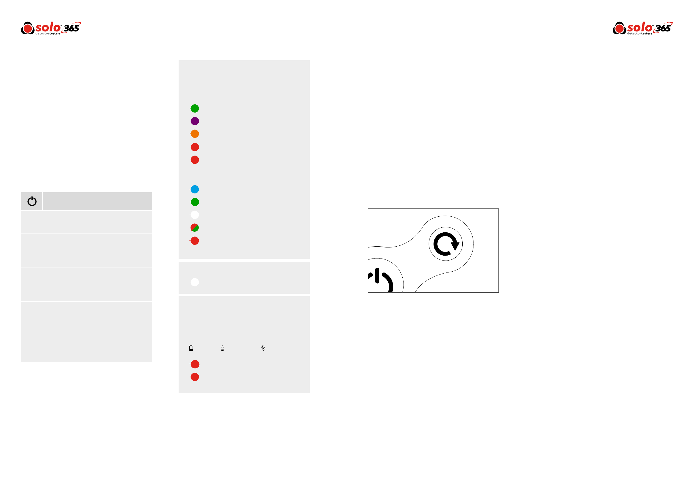
4.4 LED Indicator Reference Chart
Solo 365 has three additional LEDs to show the
status of the battery, smoke cartridge and the smoke
generator. Warnings are indicated as follows:
*After 2 minutes of testing or clearing, Solo 365 will
timeout indicated by alternate Green/Red ashing sta-
tus indicator LEDs. Exit timeout by lowering Solo 365.
Power On
Test Finish:
Testing:
Clearing:
Carefully place Solo 365 over the detector and
ensure that the detector is central in the cup.
Carefully place Solo 365 over the detector and ensure that the
detector is central in the cup.
Smoke is generated and if the detector is functional it will be
activated.
Clearing blows air into the detector to remove smoke. This
operation does not clean the internal parts of the detector. Once
detector is cleared lower Solo 365.
Status Indicator LEDs
Solo 365 indicates events as follows:
Consumable LEDs
Torch LED
When Idle:
When Active:
12 www.solo-tester.com
Battery Cartridge Generator
Flashing Red: Consumable low
Solid Red: Consumable empty
Slow ashing Green: Power on
Fast ashing Blue: Testing normally
Slow ashing Red: Consumable low
Fast ashing Green: Clearing ready
Fast ashing Red: Consumable low
Main status indicators ash fast Blue*
Main status indicators ash fast Green*
Main status indicators ash fast White*
Solid Red: Consumable empty
Fast ashing White: Clearing mode
Solid White: LED auto torch
Slow ashing Red/Green:Timeout in
testing or clearing modes
Solid Purple: System fault
Flashing Orange: Delayed start
4.3 Carrying Out a Simple Test
Smoke generation will begin automatically once the smoke
detector enters the cup.
1) Raise Solo 365 up to the detector to be tested
2) Status indicator LEDs will ash fast blue once the
detector enters the cup
3) Detector will enter alarm once sufcient smoke
has been generated
4) Lower Solo 365
5) Status indicator LEDs will ash green
NOTE: For the best results the detector should be fully
within the cup. Solo 365 may be used in ceiling voids and
oor voids provided the detectors can be accessed safely.
The unit should not be forced through narrow gaps. If
the unit will not pass through a gap easily with the cup
orientated 90° to the normal position there is a possibility
it could become trapped.
|
|
|
|
|
|
|
|
|
|
|
|
|
|
|
|
|
|
|
|
|
|
|
|
|
|
|
|
|
|
|
|
|
|
|
|
|
|
|
|
|
|
|
|
|
|
|
|
|
|
|
|
|
|
|
|
|
|
|
|
|
|
|
|
|
|
|
|
|
|
|
|
|
|
|
|
|
|
|
|
|
|
|
|
|
|
|
|
|
|
4.5 Delayed Start
On occasion it may be necessary to test detectors that do
not easily t into the Solo 365 smoke cup or are obstructed
in some way. To allow testing of such detectors or aspirating
smoke detection systems, Solo 365 has the facility to allow
a 20 second delayed start of a test.
• This feature can be activated by pressing the
function button on the front of the unit (Fig. 5)
momentarily (<1 second). The status indicators
will ash orange for 20 seconds allowing time to
reach the detectors/aspirating pipes.
• The status indicator LEDs will ash fast blue indicating
smoke generation for 20 seconds during which time
Solo 365 should be in proximity to the detector and/or
aspirating sample point.
• After 20 seconds of smoke generation the unit returns
to idle state and the status indicator ashes slow green.
13
www.solo-tester.com
4.6 Clearing a Detector
Once activated any lingering smoke can be cleared from
the detector using the ‘Clearing mode’. Air is blown around
the detector – clearing any lingering smoke via the vent in
the cup.
1) After the detector activates lower Solo 365 so the
detector is clear from the cup
2) The Status Indicator LEDs will ash fast green
3) Raise the unit over the detector again whilst the
status indicator LEDs are ashing fast green
4) The Status Indicator LEDs will ash fast white –
indicating clearing mode
After clearing, the unit will return to idle state ready for the
next test.
NOTE: Clearing mode is not available when using the
delayed start feature.
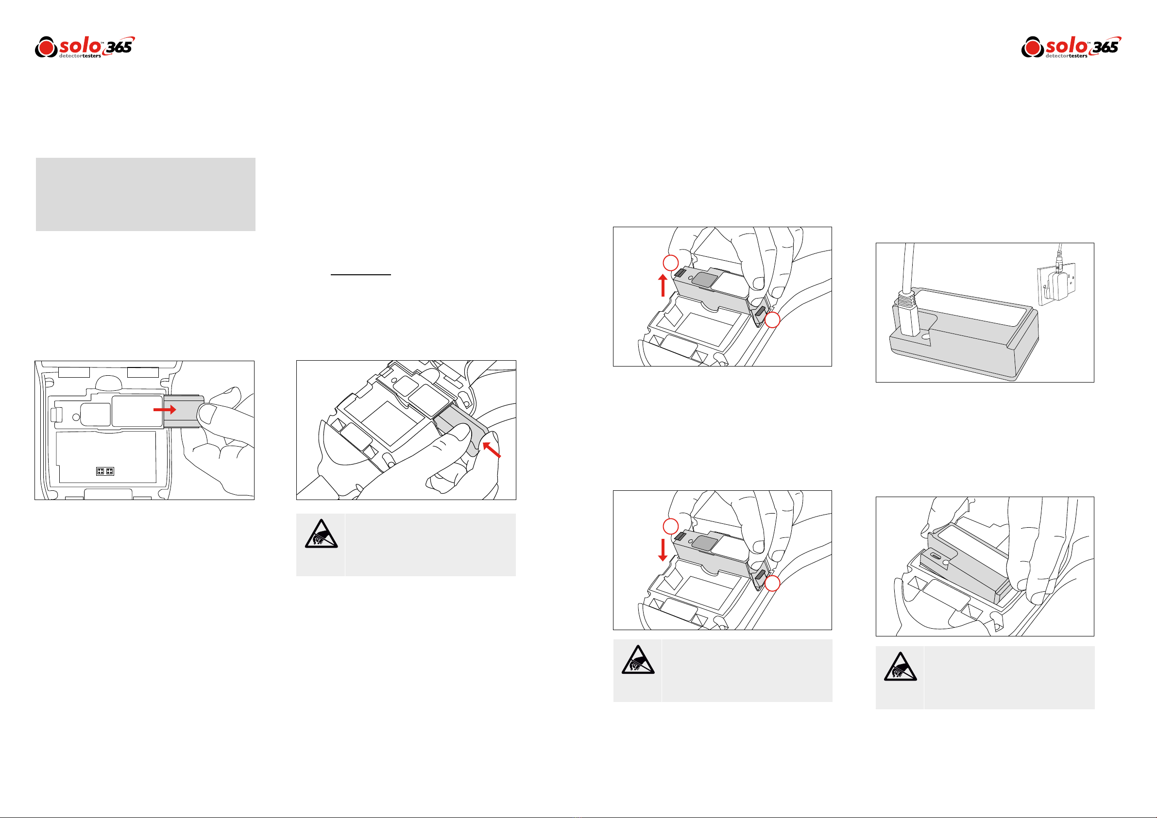
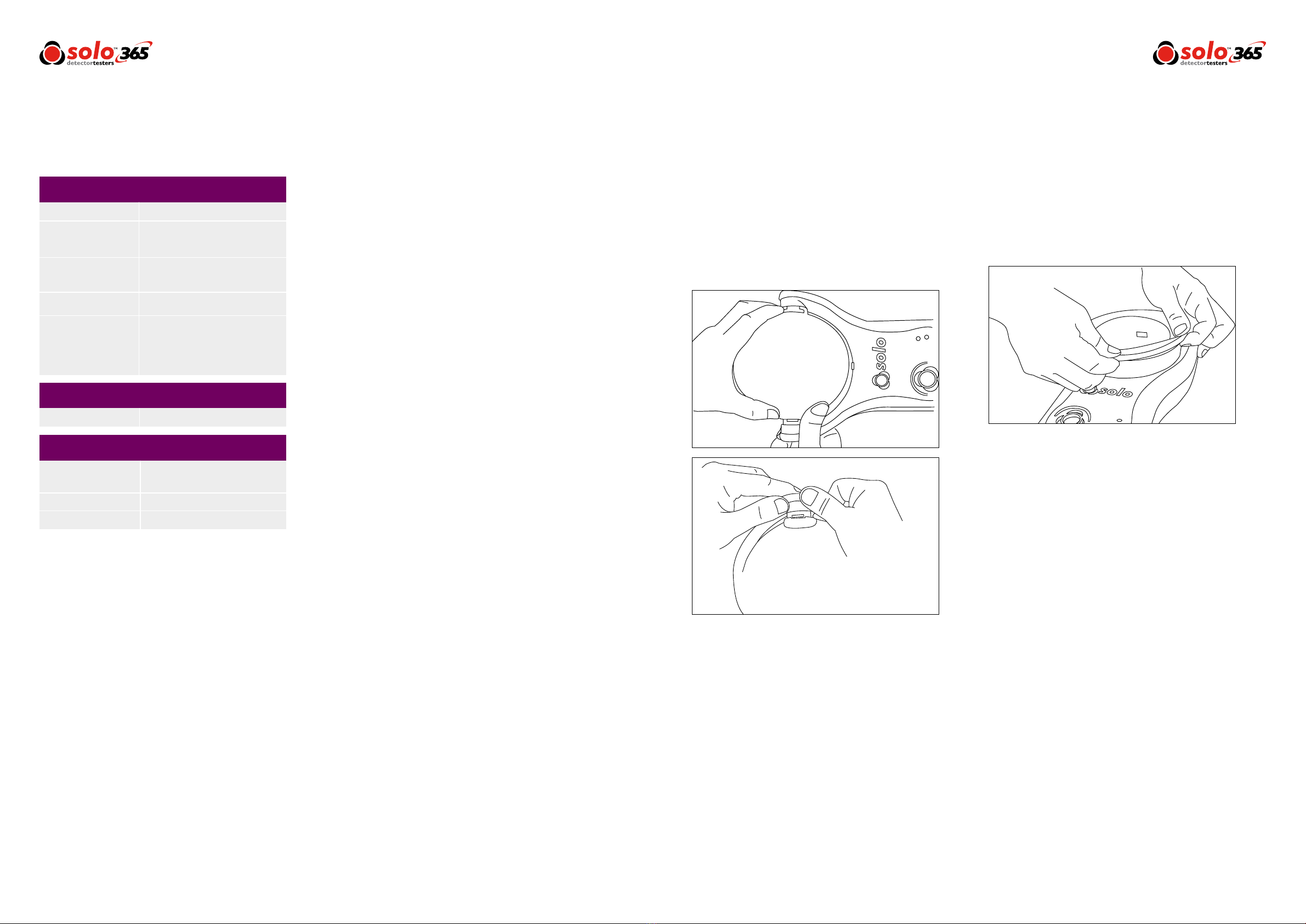
4.8 Testing an ASD System
An ASD System can be tested by using the ‘Delayed Start
Mode’ and replacing the cup with the Solo 365 ASD
Adaptor (Product Code: Solo 372-001).
1) With the unit facing you, remove cup by aligning
the notch on the left hand
side arm and disengage by squeezing the cup and
gently pulling the arm outwards
2) Rotate the cup to free it from the other arm
3) Fit the adaptor by locating into both arms
4) Raise the unit over the sampling hole and initiate
the test using the delayed start mode (Section 4.5)
4.9 Manual Purge
A manual purge may be required when the unit has not
been used for a period of time or in the case of a signicant
drop in performance. A manual purge should be carried out
in a well ventilated area as follows:
1) Hold down the function button continuously,
during this time Solo 365 will attempt to
generate smoke
2) When smoke has been observed for
approximately ve seconds release the
function button
3) Solo 365 will return to idle state – ready for
normal use
Figure 5
4.7 Using the LED Torch
In low light levels an LED torch will automatically illuminate
from underneath the cup. This makes for easy alignment
and testing of detectors in dark environments.
Upon alignment and the starting of the test the LED torch
will switch off allowing a clear view of the detector LED
through the cup.