Solon VASCO Solar 212 User manual

VASCO Solar.
Installation and Operating Manual.

2
Index
1. VASCO Solar Introduction.................................................................................................................................................. 3
2. Safety Instructions............................................................................................................................................................. 4
3. Technical Characteristics ................................................................................................................................................... 5
3.1 Weight and dimensions .......................................................................................................................................................... 5
4. Electric wiring.................................................................................................................................................................... 6
4.1 Protections............................................................................................................................................................................... 8
4.2 Electromagnetic compliance.................................................................................................................................................... 8
4.3 Installation with long motor cables ......................................................................................................................................... 8
5. VASCO Solar installation.................................................................................................................................................... 9
6. PV system sizing ...............................................................................................................................................................10
7. VASCO Solar Installation for constant pressure control .......................................................................................................... 11
7.1.1 Pressure tank .............................................................................................................................................................. 11
7.1.2 Pressure sensor ........................................................................................................................................................... 12
8. VASCO Solar Use and Programming..................................................................................................................................12
8.1 VASCO Solar display .............................................................................................................................................................. 12
8.2 Initial configuration ............................................................................................................................................................... 13
8.3 Initial view ............................................................................................................................................................................. 14
8.4 Menu view............................................................................................................................................................................. 15
8.5 Installer parameters.............................................................................................................................................................. 15
8.6 Advanced parameters ............................................................................................................................................................ 21
9. Protections and alarms.....................................................................................................................................................23
10. Auxiliary pumps during constant pressure control..........................................................................................................25
10.1 DOL pumps.......................................................................................................................................................................... 26
10.2 COMBO function .................................................................................................................................................................. 27
11. Trouble-shooting chart ...................................................................................................................................................29
12. Technical Assistance .......................................................................................................................................................30
manVASCO_Solar_eng_02_SOLON.docx
3
1. VASCO Solar Introduction
VASCO Solar Solar inverters come to power traditional pumping systems using photovoltaic energy.
In this way it’s possible to convert old systems in renewable energy installations or to use the same AC pumps in the creation
of independent, cost-saving and environmentally sustainable water systems.
VASCO Solar Solar is able to convert DC voltage coming from photovoltaic panels into AC voltage for powering any pump
driven by three phase asynchronous motor.
MPPT (Maximum Power Point Tracking) maximizes, for various conditions of irradiation and temperature, the electrical
power drawn from the panels so the amount of pumped water.
Pump speed is constantly adapted to available solar irradiation thus maximizing the amount of pumped water and making
possible operation even in low irradiation conditions.
VASCO Solar also offers complete pump protection against over-voltage, over-current and dry running.
VASCO Solar can be used with any type of traditional AC pump thus offering maximum flexibility in several application areas.
In the use with submersible pumps, VASCO Solar allows to fill tanks for watering livestock or simply irrigate lawns or crops.
In the use with surface pumps, VASCO Solar can serve an irrigation fishing from a nearby water reserve or feed with no
energy cost a pool pump.
5
6
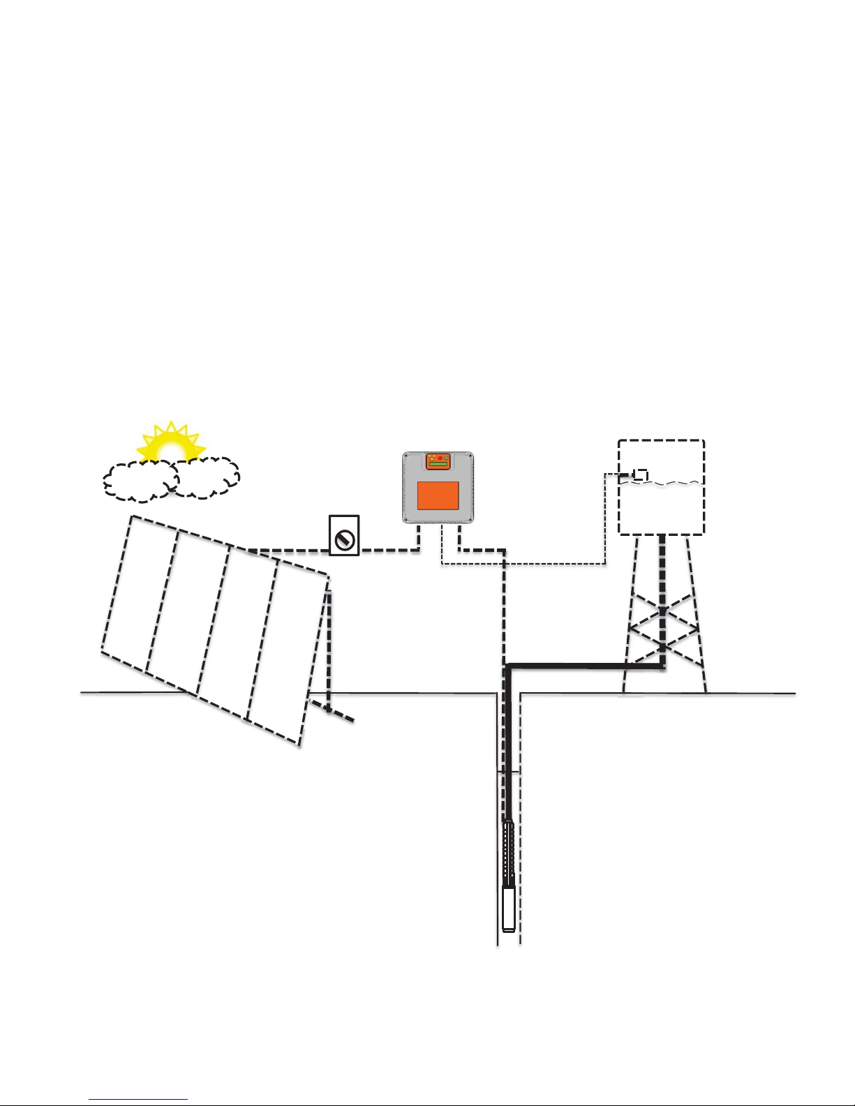
ON OFF
1. VASCO Solar
2. Submersible pump
3. DC circuit breaker
4. PV panels
5. Tank
6. Level switch
1
2
3
4

4
2. Safety Instructions
The manufacturer strongly suggests carefully reading this operation manual before using and installing its products
Any operation (installation, maintenance and repair) must be carried out by trained, skilled, and qualified personnel.
Failure to observe and follow the instructions in this manual may result in dangerous and potentially lethal electric shock.
Pay attention to all standard safety and accident prevention regulations
The device must be connected to main power supply via a switch to ensure the
complete disconnection from the network before any operation on the
VASCO
Solar
itself (including visual inspection) and/or on the connected load.
Disconnect
VASCO Solar from the power supply before commencing any work.
Do not remove, for any reason, the cover and the cable plate without having first
disconnected the device from the main power supply and having waited at least 5
minutes.
VASCO Solar
and pumping system must be grounded properly before operation.
For the entire period
VASCO Solar is powered, high voltage is present on the
output terminals of the inverter whether or not the pump is running.
Tightening all 4 screws on the cover with washers is recommended b
efore
powering the device. Otherwise, there may be a failure to connect the cover to
ground, creating the risk of electric shock or even death.
Avoid any shock or significant impact during transport.
Check the VASCO Solar immediately upon delivery and check for damage and/or missing parts. If either occurs, immediately
notify the supplier.
Damages due to transport, incorrect installation, or improper use of the device will null and void the warranty.
Tampering or disassembly of any component will automatically void the warranty.
The manufacturer cannot be held responsible for any damages to people and/or property due to improper use of its
products.
5
3. Technical Characteristics
Model Vin
Vin
P1 nom*
Max Vout
Max I out
Typical motor P2
[VDC]
[VDC]
[VAC]
[A]
[VAC]
[kW]
VASCO Solar 212
120 –650
> 320
3 x 230
12
3 x 230
2,2
VASCO Solar 409
320 –850
> 560
3 x 400
9
3 x 400
3
VASCO Solar 412
320 –850
> 560
3 x 400
12
3 x 400
4
VASCO Solar 415
320 –850
> 560
3 x 400
15
3 x 400
5,5
VASCO Solar 418
320 –850
> 560
3 x 400
18
3 x 400
7,5
VASCO Solar 425
320 –850
> 560
3 x 400
25
3 x 400
11
VASCO Solar 430
320 –850
> 560
3 x 400
30
3 x 400
15
xMax ambient temperature at nominal current: 50°C (122 °F)
xMax. altitude at nominal current: 1000 m
xGrade of protection: IP65 (NEMA 4)*
xRS485 serial communication
xPWM configurable: 2.5 ,4, 6, 8, 10 kHz
* avoid direct exposition to solar rays.
VASCO Solar Solar is able to power the motor with a higher current for a short period of time according to the linear
relation: 101% of the nominal current for 10min., 110% nominal current for 1 min.
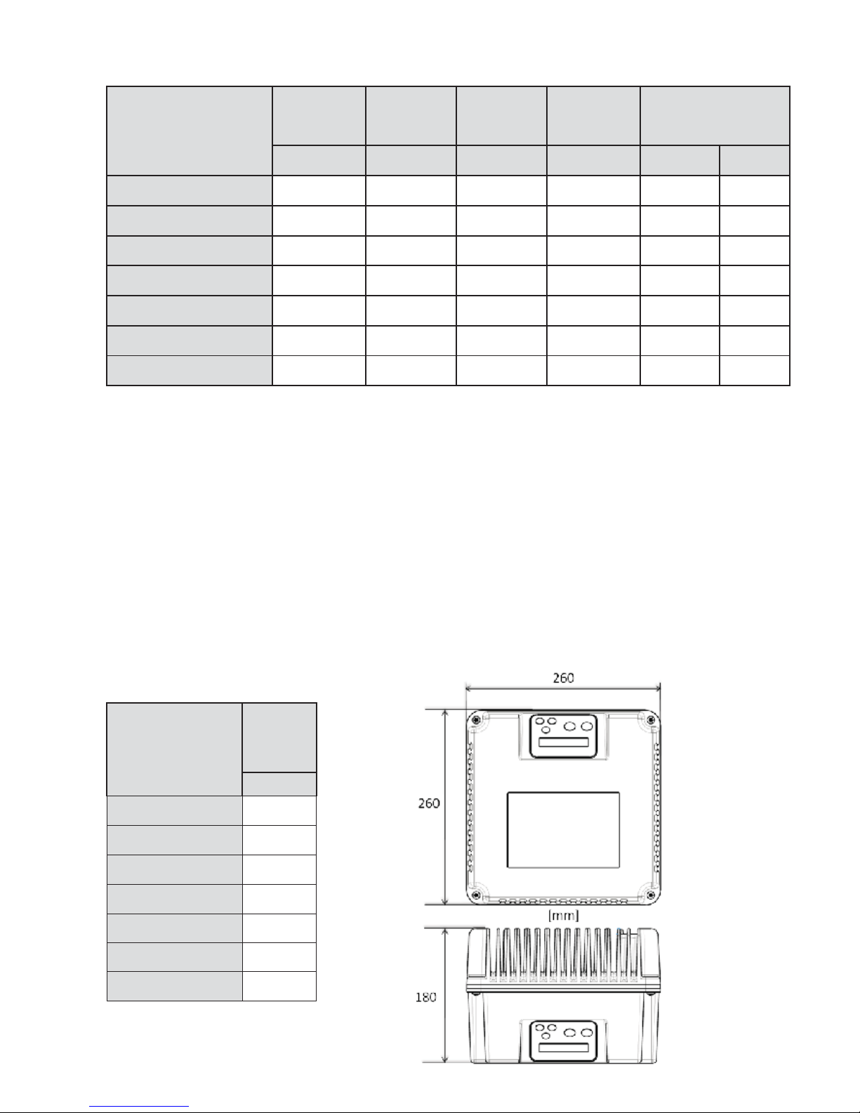
3.1 Weight and dimensions
Model
Weight
*
[Kg]
VASCO Solar 212
8,2
VASCO Solar 409
8,3
VASCO Solar 412
8,5
VASCO Solar 415
8,5
VASCO Solar 418
8,7
VASCO Solar 425
8,7
VASCO Solar 430
8,7
* Weight without packing.

6
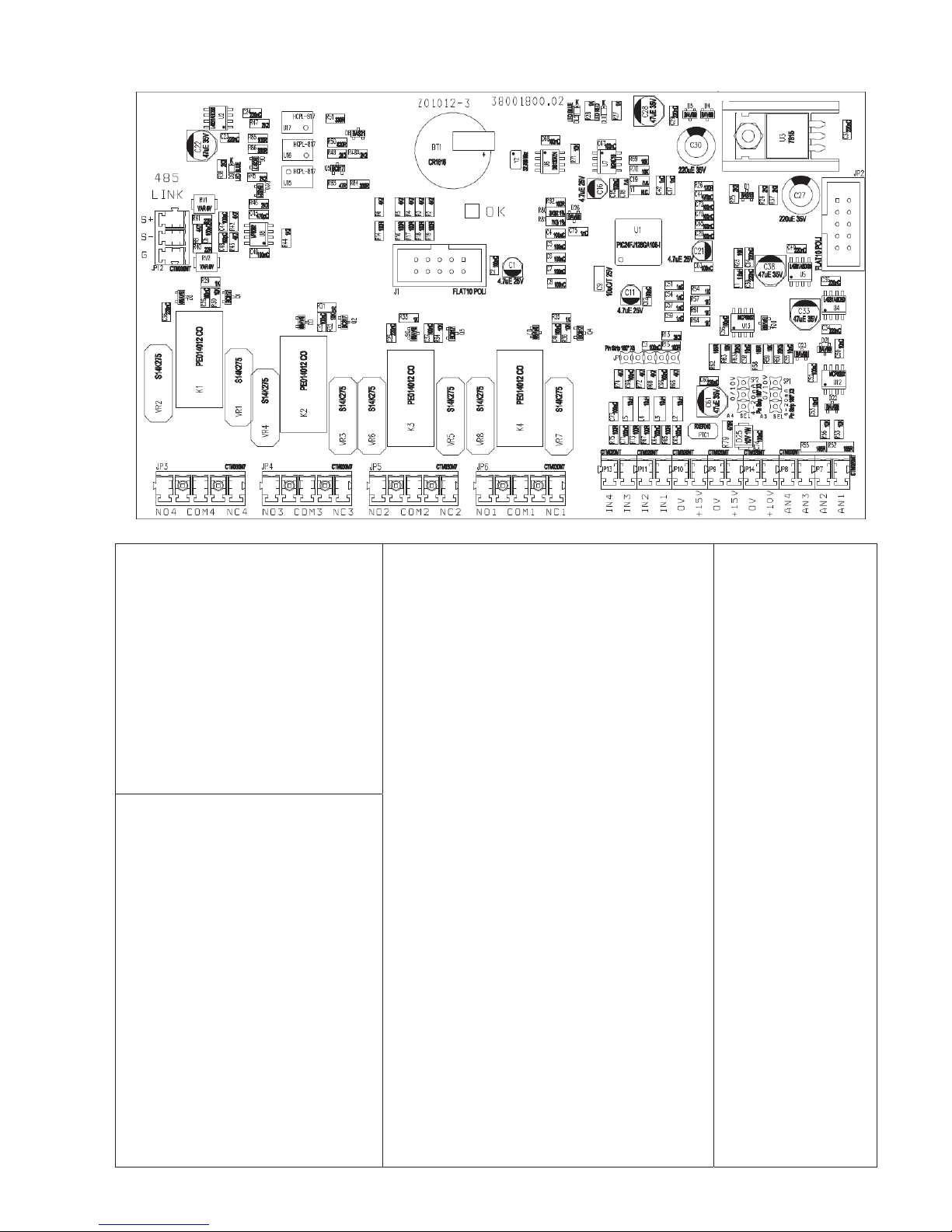
4. Electric wiring
Power board
DC Input:
LINE:
L1, L3, GND
It is recommended to use cable
lugs.
It is not necessary to
respect
polarity.
Motor output:
MOTOR: U, V, W, GND
It is recommended to use cable
lugs.
12 V dc auxiliary fans (wall
mounting kit)
VENT: +,
-
WARNING: respect the polarity.
Cable stripping recommended for line input and output to the motor.
7
Control board
Analog inputs (10 or 15 Vdc):
1.
AN1: 4-20 mA: sensor 1
2.
AN2: 4-20 mA: sensor 2
3.
AN3: 4-20 mA / 0 - 10 Vdc
(settable by jumper C.C.):
external set
4.
AN4: 4-20 mA / 0 - 10 Vdc
(settable by C.C.): trimmer for
frequency regulation
/ external
set 2
Digital outputs:
xmotor run signal:
NO1, COM1: closed contact with motor
running.
NC1,COM1: closed contact with motor
stopped.
xalarm signal
NO2,COM2: opened contact without alarm.
NC2,COM2: closed contact without alarm.
xDOL1 pump relay:
NO3,COM3: closed contact
with DOL1
running.
NC3,COM3: opened contact with DOL1
running.
xDOL2 pump relay:
NO4,COM4: closed contact with DOL2
running.
NC4,COM4: opened contact with DOL2
running.
Relays are no voltage contacts. Max.
voltage to the contacts is 250 V with max
current
of 5 A.
RS485:
xS+
xS-
xG
It is recommended
to respect the
polarity linking
more
VASCO Solar
s
in series.
Digital inputs:
xIN1 : motor start & stop
xIN2: value set 1 & 2 switching
xIN3: sensor 1 & 2 switching
xIN4 : motor start & stop +
alarms reset
x0V
We
recommend using only no
voltage contacts.
Opening or closing the digital
contacts (depending on software
configuration set (see inst.
parameters) you can start or stop
the motor.
8
4.1 Protections
The protections required upstream each VASCO Solar depends on the type of installation, and local regulations. We
recommend to use 1000 VDC, 16 A circuit breaker and, if possible, 1000 VDC surge protection.
4.2 Electromagnetic compliance
To ensure electromagnetic compatibility (EMC) of the system, it is necessary to apply the following measures:
xAlways connect the device to ground
xUse shielded signal cables by placing the screen at one end.
xUse motor cable as short as possible (<1 m / <3 ft). For longer lengths, it is recommended to use shielded cables
connecting the screen at both ends.
xSeparate signal, motor, and power supply cables.
Note: To enable the restoration of the display screen when there are electromagnetic interference, VASCO Solar
periodically provides some fast "refresh" of the display.
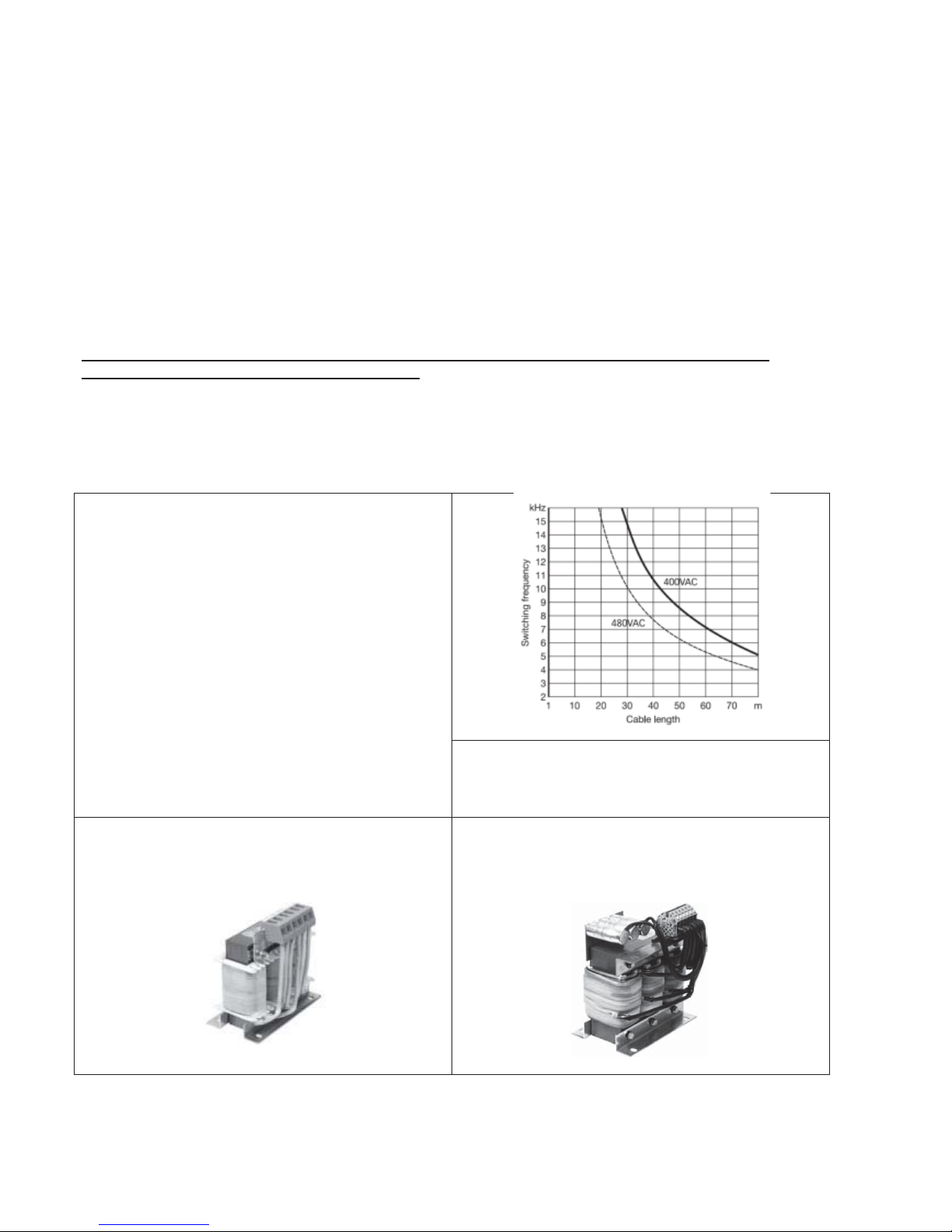
4.3 Installation with long motor cables
With long motor cables it’s recommended to decrease the
commutation frequency from 10 kHz (default) to 2.5 kHz
(advanced parameters). This reduces the probability of
voltage spikes in the motor windings which may damage the
insulation.
To prevent dangerous overheating of dv / dt and sinusoidal
filters it is recommended to set the correct PWM value in
relation to the
cable length.
For motor cable lengths up to 50 meters it’s recommended
to place between
VASCO Solar and motor a dv / dt
reactance, available on request.
For motor cable lengths greater than 50 meters it’s
recommended to place between
VASCO Solar and motor a
sinusoidal filter, available on request.

9
5. VASCO Solar installation
xn.° 2 12 V DC fans.
xn.° 1 fans cover.
xn.° 2 fans cover fixing screws
xn.° 2 wall fixing brackets
xn.° 4 M5 screws for VASCO Solar fixing to the brackets
xn.°1 holes reference sheet
10
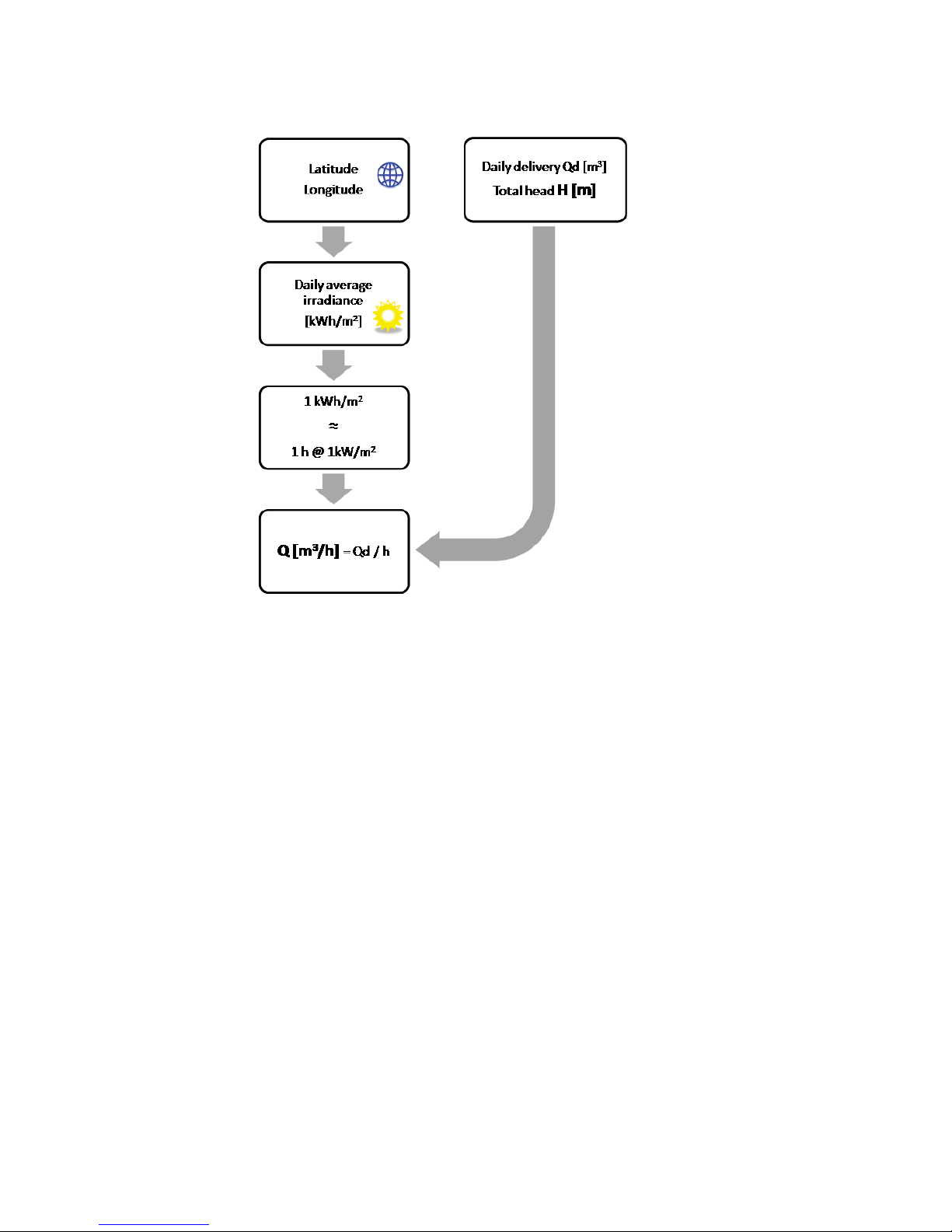
6. PV system sizing
The pumping system must be designed considering daily flow rate required, total head and installation site.
In particular, the choice of the pump must be carried out considering the average daily radiation.
Once determined the required pump, must need to know:
xRated pump power (P2)
xElectrical motor power (P1). P1 can be derived by dividing P2 with motor efficiency.
xRated motor current
xRated motor voltage (3 x 230 VAC or 3 x 400 VAC)
VASCO Solar model to be used is determined by considering voltage and rated motor current.
To ensure maximum performance, the PV system, consisting of 1 or more strings of solar panels connected in series, must
provide:
xElectrical motor power (P1)
The photovoltaic power (Wp) must be at least equal to the electric motor power (P1). Typically, taking into account the
efficiency loss due to panels temperature, it is recommended to increase Wp of 15% respect to P1.
xRated motor voltage at maximum power
The rated voltage of each PV string (Vmp) must be at least equal to the rated motor voltage multiplied by the factor 1,4.
xThe open-circuit voltage of each string (Voc) must be less than the maximum operating voltage of VASCO Solar.
Example:
Pump nameplate
xRated motor power: P2 = 3 kW
xElectric motor power: P1 = 4 kW
xRated motor current: 8.3 A
xRated motor voltage: 3 x 400 VAC
11
VASCO Solar selection
Being the rated motor voltage 400 VAC and the rated current 8.3 A, the most suitable model for the application is VASCO
Solar 409.
PV system sizing
PV panels used:
xWp = 240 W
xVmp = 30 VDC
xVoc = 37 VDC
xImp = 8 A
Since P1 = 4 kW, considering efficiency loss due to temperature, the required electrical power is increased of 15% so Wp =
4.6 kW.
To develop 4.6 kW are needed 19 panels of 240 W.
Vmp = 19 x 30 = 570 VDC is greater than the rated motor voltage multiplied by 1.4 (400 x 1.4 = 560 VDC) and Voc = 19 x 37 =
703 VDC is less than the maximum voltage of VASCO Solar 409 (850 VDC).
For this reason a single string of 19 PV panels can be installed.
7. VASCO Solar Installation for constant pressure control
VASCO Solar, apart from MPPT control, offers other several operation modes such as constant pressure with 1 or 2 reference
values.
This last operation mode is particularly indicated in those plants where it’ s preferred to store electrical energy in batteries
and use it when it occurs.
To ensure maximum energy saving, and lengthen batteries life, it’s useful to select constant pressure mode in which the
pump speed, and so the power consumption, is varied while maintaining a constant desired pressure.
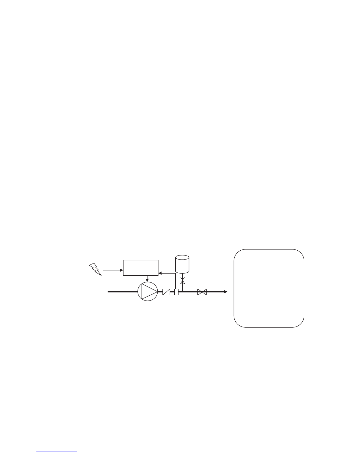
VASCO Solar controls the pump speed to maintain constant pressure at a set point independent of the water demand in the
system. A basic schematic is shown below:
7.1.1 Pressure tank
Installation of a pressure tank in the hydraulic system is recommended to compensate leakage of water in the system (or
during minimum water demand) and to avoid continuous start/stop cycling of the pump (check the appendix for more
information). Selecting the proper volume and pre-charge pressure of the tank is very important; smaller tank volumes will
not compensate adequately for minimum water usage or leakage, while larger volumes make it more difficult for VASCO
Solar to control the pressure evenly.
Recommended tank volume is equal to the 10% of the maximum water flow of the system (expressed in volume unit/min)
Example: if the max water flow is 50 liters/min, the pressure tank should have a capacity of 5 liters
If the max water flow is 20 gpm, the pressure tank should have a capacity of 2 gallons
Pre-charge pressure of the pressure tank should be at least 80% than the set-pressure of the system.
Example: if the set-pressure of the system is 4 bar, the pre-charge pressure of the tank should be 3.2 bar
If the set-pressure of the system is 60 psi, the pre-charge pressure of the tank should be 48 psi
VASCO Solar
1
2
3
5
4
1: pump
2: check valve
3: pressure tank
4: valve
5: valve
6: pressure sensor
6
12
7.1.2 Pressure sensor
VASCO Solar requires a pressure sensor with a linear output signal within the range 4 –20 mA. The pressure transducer can
be powered by any range of DC Voltage which includes the value 15 V dc.
VASCO Solar accepts the signal of a second pressure sensor in order to:
xrealize constant differential pressure (AN1 –AN2).
xsubstitute first pressure sensor when it fails
xswitch pressure sensor by closing digital input IN2
SENSOR 1
xAN1: 4-20 mA (-) signal
x+15V: 15 Vdc (+) power supply
SENSOR 2
xAN2: 4-20 mA (-) signal
x+15V: 15 Vdc (+) power supply
8. VASCO Solar Use and Programming
VASCO Solar software is extremely simple to use, but allows a wide variety of parameters to be set for ideal system
calibration. Setting Parameters are organized in 2 levels:
1: Installer level
A password is required for this level; these parameters are adjustable by trained professionals
Default password: 001
From the menu a different password can be set up.
2. Advanced level
A second and different password is required; improper setting of these advanced parameters could compromise the
integrity and the life of VASCO Solar and pump;
Default password 002
It is possible to set up a different password.
Installer and Advanced levels can be entered only with the correct password; otherwise, it is impossible to set up
and/or modify any parameters (they can be only displayed).
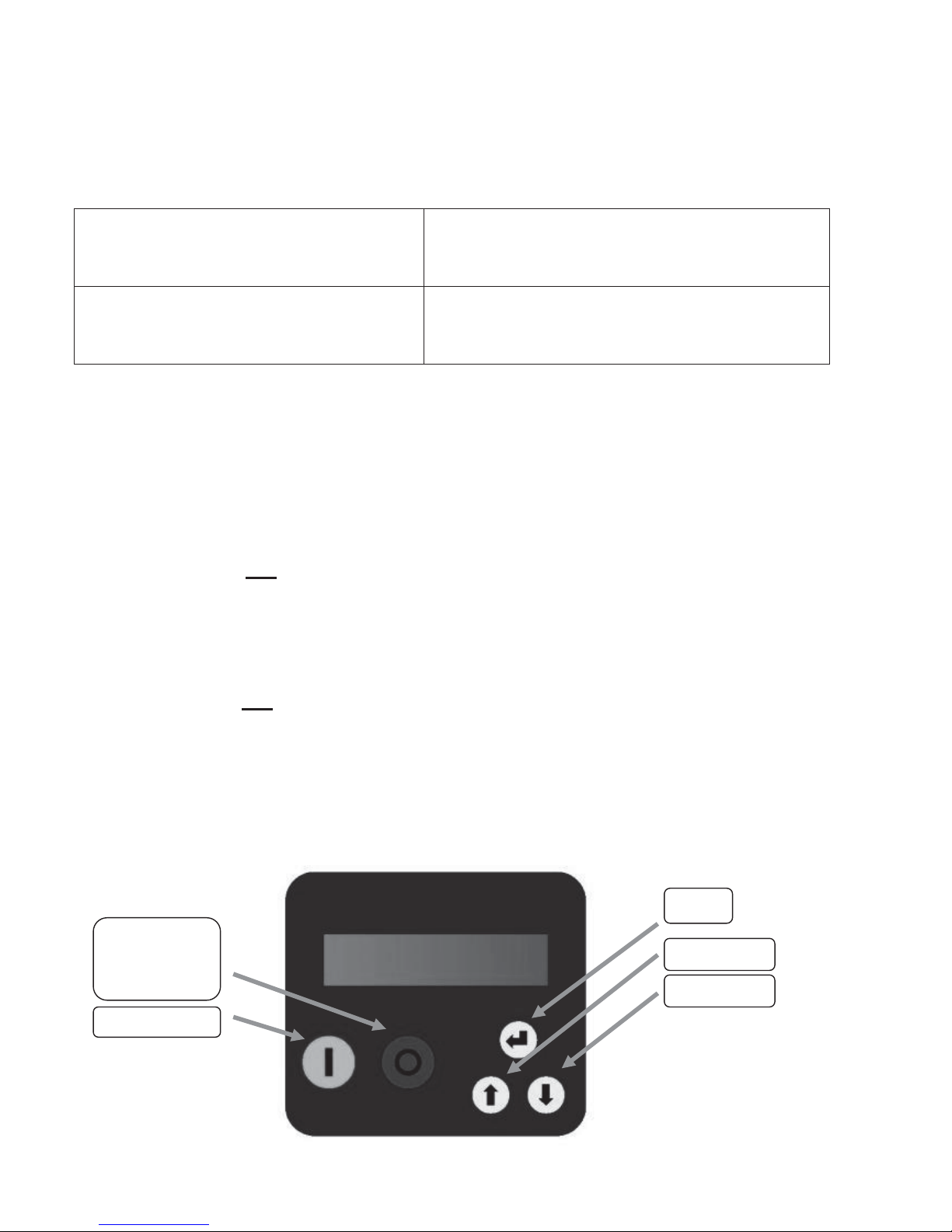
8.1 VASCO Solar display
Screen is a back-lit LCD displaying 2 rows of 16 digits each. Alarms are indicated by an audible signal.
STOP motor
Menu exit
Alarms reset
START motor
ENTER
Scroll up
Scroll down

13
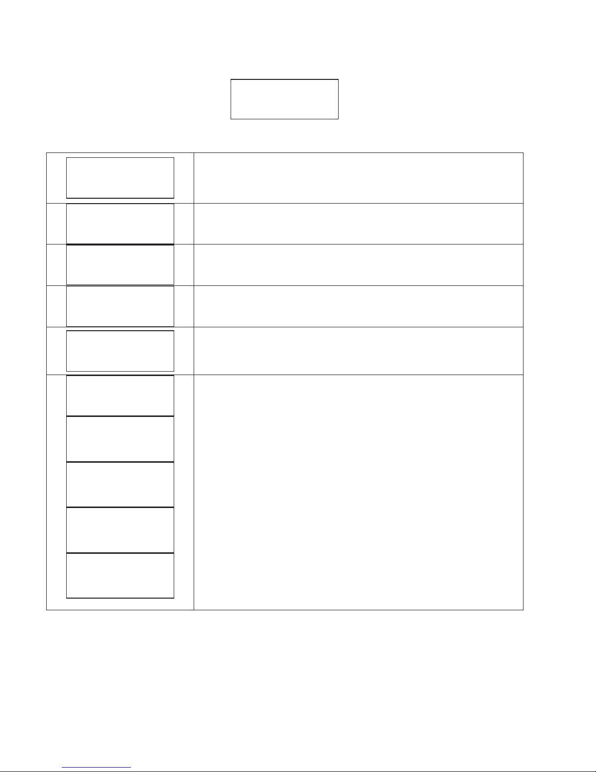
8.2 Initial configuration
When VASCO Solar is switched on for the first time, the initial setting menu is displayed for the initial setting of parameters
to configure pump and system characteristics.
If the initial setting procedure is not completed properly, it is impossible to run the pump. Initial setting procedure can be
repeated if necessary.
The initial setting procedure can be repeated (by using the 2rd level password) to reconfigure VASCO Solar or if VASCO Solar is
installed in a different system.
A brief description of parameters and their allowable ranges are listed below:
Parameter
Default
Description
XXXX
End user communication language
XXX
Open circuit voltage of PV strings. Please refer to PV panels
datasheet.
XXX
Motor rated voltage (as shown in the motor plate)
Average voltage drop due to the inverter is between 20 V and 30
Vrms based on load condition.
XX
Rated current of the motor per it’s nameplate indication increased by
10%. The voltage drop caused by the inverter leads to higher input
current than nominal. Make sure motor is capable of accepting
increased current.
50
Rated frequency of the motor per its nameplate.
Control mode: MPPT
Press START/STOP to run a test at rated frequency
Warning: make sure to run the system without damaging pump and
system
--->
If, during the test, the motor runs in reverse, it is possible to change
the wiring sequence via software without physically changing wires at
the terminals.
OFF
If ON is selected, after a lack of voltage, VASCO Solar returns to its
normal status; if
VASCO Solar was powering the pump before the
voltage drop, it resumes powering the pump automatically.
Warning, review the advice in chapter 1
Once the Setting procedure is completed you will get this indication
on the display; setting parameters are recorded by
VASCO Solar;
these parameters can be set up individually in the INSTALLER
Parameters menu or ADVANCED Parameters menu.
INITIAL SETUP
COMPLETED
Autorestart
ON/OFF
Rotation sense
---> / <---
Motor test
START/STOP
Rated motor freq
f = XXX [Hz]
Rated motor Amp.
I = XX.X [A]
Rated motor Volt.
V = XXX [V]
Open circuit Volt. PV
V = XXX [V]
Language
XXXXXX
14
8.3 Initial view
When first powering the VASCO Solar, the display shows : release of display software (LCD = X.XX) and the release of
inverter software (INV = X.XX) as shown below:
The following End User messages are displayed by pushing the scroll buttons:
p is the pressure value read by the pressure transducer.
By pressing ENTER the pressure set value is displayed
<XXX.X>
V_in is the line voltage.
I is the the absorbed motor current.
cosphi index means the angle phi between the voltage and current absorbed by the
motor
P is the power in Watts supplied to the pump.
NORMAL status means no alarms.
If an alarm occurs, a message blinks on the display and an audible signal is activated.
Pressing ENTER accesses:
VASCO Solar lifetime, PUMP lifetime,
consumption statistic,
alarm list.
To return to previous views, press ENTER.
First row gives the VASCO Solar status:
xInv: ON XXX.X Hz VASCO Solar is powered and is powering the motor showing its frequency.
xInv: ON Mot: OFF VASCO Solar is powered but motor is not running
xInv: OFF Mot: OFF VASCO Solar is not powered
If COMBO function is activated, the VASCO Solar address is placed close to indication “Inv”.
XXXXXXXXXXXXXXX
XXXXXXX h : XX m
%f 25 50 75 100
%h XX XX XX XX
Motor Life
xxxxx h : xx m
Inverter Life
xxxxx h : xx m
Inv: ON/OFF Mot: ON/OFF
STATUS: NORMAL
Inv: ON/OFF Mot: ON/OFF
P = XXXXX [W]
Inv: ON/OFF Mot: ON/OFF
cosphi = XXX
Inv: ON/OFF Mot: ON/OFF
I= XX.X [A]
Inv: ON/OFF Mot: ON/OFF
V_in = XXX [Hz]
Inv: ON/OFF Mot: ON/OFF
p = XX.X [bar]
LCD = X.XX
INV = X.XX
15
8.4 Menu view
Pressing ENTER when you are in [MENU’ / ENT to access] in initial display, will display the following MENUs:
Installer password required to enter level 1 (default 001)
Advanced password required to enter level 2 (default 002)
Installer password required to enter level 1 (default 001)
It is possible to return to original set parameters.
Advanced password required to enter level 2 (default 002)
To exit the Menu level and return to initial display, press STOP button.
8.5 Installer parameters
Many of the Installer parameters are set during the Initial Configuration (chapter 6.2 Initial Configuration).
However, through the Installer Parameters menu, it is possible to change the set parameters or set others in order to perfect
the calibration of VASCO Solar to the pumping system.
parameter
default
desciption
MPPT
Constant
value
Fix speed
Const.
value 2 set
Fix speed 2 val.
External speed
MPPT
Mode of control:
x
MPPT: pump speed is adjusted in order to obtain maximum power
available from PV panels.
xConstant value: VASCO Solar
changes the speed of pump to keep
the set value constant, independent of water demand.
xFix speed: VASCO Solar feeds the pump a set frequency, so the
speed of motor is kept constant.
xConst. value 2 set: the two values are selected by opening or
closing the digital input IN2.
xFix speed 2 val: to be selected by opening or closing the digital
input IN2.
x
External speed: control motor frequency by using analogical input
AN4.
bar
Unit
9
9
9
9
9
9
16
Sensor full scale.
9
9
9
9
9
9
F. scale sensor
p = XX.X [bar]
Unit
XXXXX
Control mode
xMPPT
xConstant value
xFix speed
xConst.value 2
set
xFix speed 2 val.
x
External speed
MENU’
Change init.set.
MENU’
Retrive init.set
MENU’
Advanced. param.
MENU’
Install. param.

16
parameter
default
desciption
MPPT
Constant
value
Fix speed
Const.
value 2 set
Fix speed 2 val.
External speed
0
Sensor minimum value.
9
9
9
9
9
9
10
Maximum value allowed in the
system. If the
readen value goes
over this value, an alarm occurs and
the pump is stopped. Pump is
automatically restarted if the
readen value
goes below the
maximum value for a period of
at
least 5 seconds.
9
9
9
9
9
9
0
Minimum value allowed in the
system. If the
readen value goes
lower than
this value, an alarm
occurs and the pump is stopped.
Pump is automatically restarted if
the
readen value
goes higher than
the minimum value for a
period of
at least 5 seconds.
9
9
9
9
9
9
OFF
Enabling of set value changing by
analog input AN3.
9
9
3
The set value to be kept constant.
9
0
Value compensation at the
maximum frequency for each pump.
Acting on the green button you can
reverse the sign.
9
3
The set value to be kept constant.
9
0
Value compensation at the
maximum frequency for each pump.
Acting on the green button you can
reverse the sign.
9
5
Time to update set value for
compensation.
9
9
Set value update
t = XX [s]
Compensation 2
p = XX.X [bar]
Set value 2
p = XX.X [bar]
Compensation
p = XX.X [bar]
Set value
p = XX.X [bar]
Ext.set enabling
ON/OFF
Min alarm value
p = XX.X [bar]
Max alarm value
p = XX.X [bar]
Min value sensor
p = XX.X [bar]
17
parameter
default
desciption
MPPT
Constant
value
Fix speed
Const.
value 2 set
Fix speed 2 val.
External speed
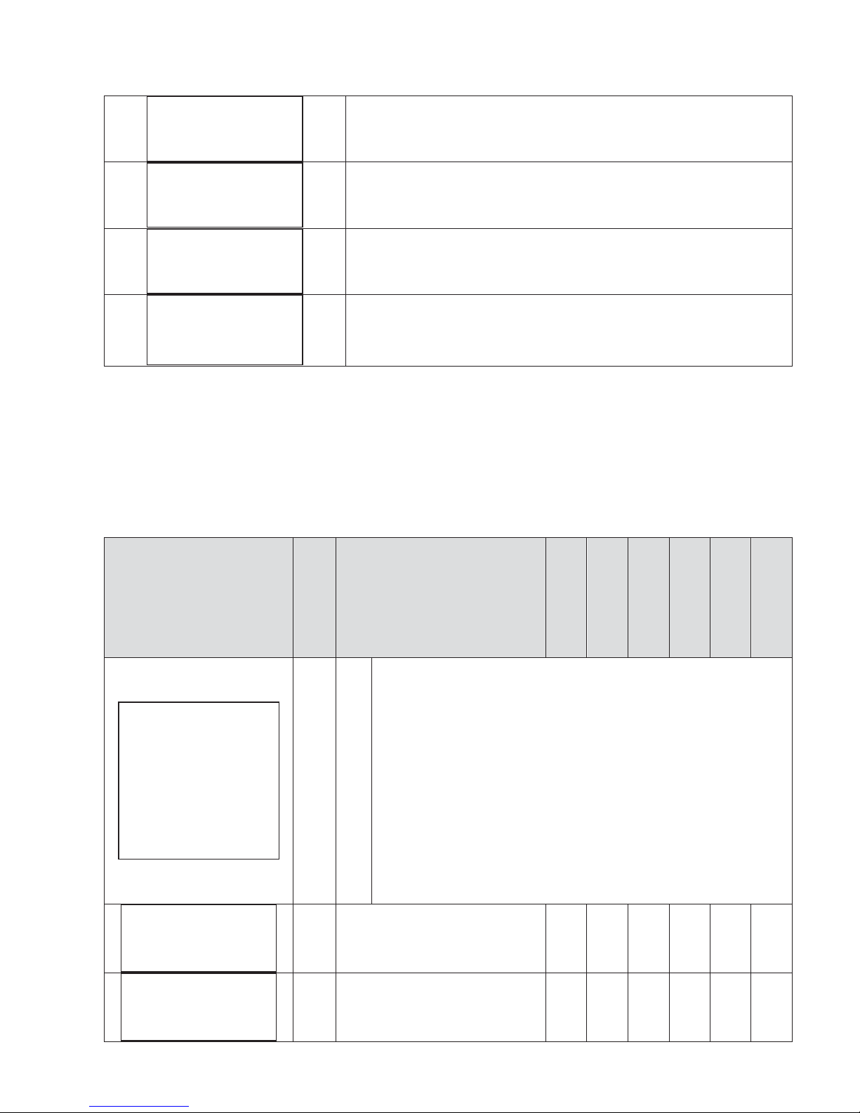
To ensure proper operation of pressure control is recommended to place the sensor near the pump.
To compensate the pressure loss in the pipes (proportional to flow)
it is possible to vary the pressure set in a linear relation
with respect to frequency.
It can perform the following test to verify the correct value of compensation:
1. install a pressure gauge away from the pressure sensor
2. open completely the
valve
3. check the pressure gauge
--
> Set the value of compensation. equal to the difference of the values from the two gauges.
When using a group of pumps, the pressure compensation to be applied to each pump is equal to the total pressure
compensation (when all the pumps are running at full speed) divided by the number of pumps in the group.
50
Set the frequency value to feed the
pump.
9
50
Set the frequency value to feed the
pump.
9
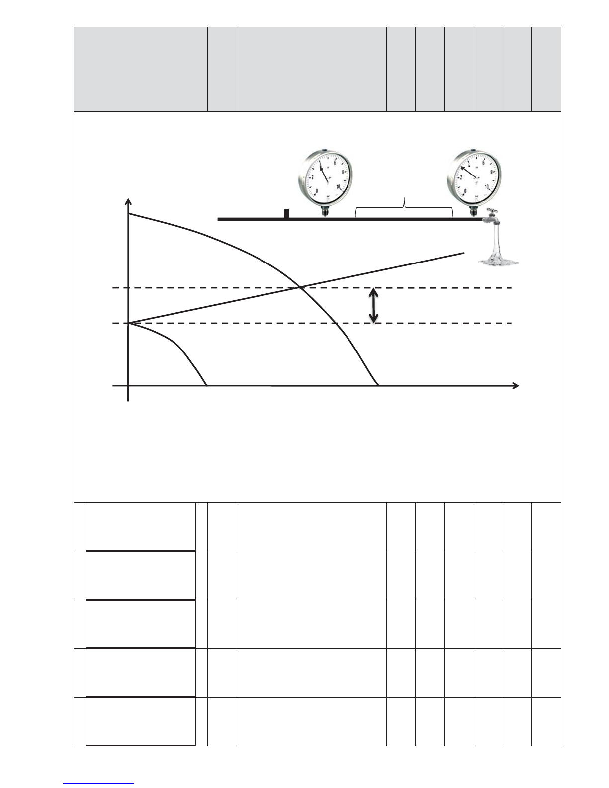
50
Minimum frequency below which
the pump
tries to stop.
9
9
9
5
Delay for which the pump tries to
stop
below freq.min. control.
9
9
9
20
Ramp time from freq.min.control to
min.motor freq.
If, during this time,
the
readen value goes below the
(
set value - delta control), VASCO
9
9
9
Q
H
Min mot. freq. Max mot. freq.
Set value (3 bar)
4 bar
Pressure
sensor
300 m
Compensation (1 bar)
Control ramp
t = XX [s]
Stop delay
t = XX [s]
Freq.min.control
fmin = XXX [Hz]
Operating freq. 2
f = XXX [Hz]
Operating freq.
f = XXX [Hz]
18
parameter
default
desciption
MPPT
Constant
value
Fix speed
Const.
value 2 set
Fix speed 2 val.
External speed
Solar powers the motor again;
otherwise,
VASCO Solar
will stop the
pump.
0.
1
This value represents the value drop
below the
set value required to
re
start the pump during control
ramp.
9
9
0.
5
This value represents the value drop
below the set
value required to
start the pump
from stop condition.
9
9
0.5
It's the value increase respect to set
value
which must be passed so that
there is a forced shutdown of the
pump.
9
9
Kp and Ki parameters allow the
dynamic control of system by
VASCO Solar
; set values (Ki=50,
Kp=005) are usually enough to get a
valid dynamic control
.
9
9
9
OFF
Function to activate (ON) the first
auxiliary pump DOL 1 (Direct On
Line pump).
9
9
OFF
Function to activate (ON) the
second auxiliary pump DOL 2 (Direct
On Line pump).
9
9
OFF
Function to allow alternating
starting priority between the DOL
pumps in order to allow equal use
of them.
9
9
sec
Hz
Freq.min.control
press.
Set value
Min mot. freq
Stop delay Control ramp
Delta control
Alternance
ON/OFF
Pump DOL 2
ON/OFF
Pump DOL 1
ON/OFF
Kp
XXX
Ki
XXX
Delta stop
p = XX.X [bar]
Delta start
p = XX.X [bar]
Delta control
p = XX.X [bar]

19
parameter
default
desciption
MPPT
Constant
value
Fix speed
Const.
value 2 set
Fix speed 2 val.
External speed
1
delay time with which the pumps
DOL start after the variable speed
pump has reached the maximum
frequency and the
readen
value has
fallen below set
value –delta
control.
9
9
OFF
Function to enable multiple VASCO
Solar
’s to work in parallel as
described in the technical appendix
(see the relevant chapter). Up to 8
VASCO Solar
units can be connected
in parallel.
VASCO Solar
’s communication
through RS 485 gates is granted by a
private protocol.
9
9
Direct
Direct: increasing measured value,
VASCO Solar
decreases motor
frequency.
Re
verse: increasing measured
value,
VASCO Solar
increase motor
frequency.
9
9
---
>
If, during the test, the motor runs in
reverse, it is possible to change the
wiring sequence via software
without physically changing wires at
the terminals.
9
9
9
9
9
9
0.65
If the pump goes into dry-running,
the cosphi reaches its lowest level.
To set this value, contact the pump
manufacturer or test by closing the
suction and checking the value on
the
VASCO Solar
display; a value can
be set by assuming a dry cosphi
equivalent to 60% of the rated
cosphi specified by the
manufacturer.
9
9
9
9
9
9
10
Restart delay after a dry running
alarm. At each tentative (max 5)
restart delay will be doubled.
9
9
9
9
9
9
N.O.
By selecting N.A. (normally open)
VASCO Solar
runs the motor if the
digital input 1 is open; motor will
be stopped if the digital input 1 is
closed.
By selecting N.C. (normally closed)
VASCO Solar
runs the motor if the
digital input 1 is closed; motor will
be stopped if the digital input 1 is
opened.
9
9
9
9
9
9
N.O.
By selecting N.A. (normally open)
VASCO Solar
runs the motor if the
digital input 2 is open; motor will
be stopped if the digital input 2 is
closed.
9
9
9
9
9
9
Digital input 2
N.O. / N.C.
Digital input 1
N.O. / N.C.
Restarts delay
t = XX [min]
Dry run cosphi
cosphi = X.XX
Rotation sense
---> / <---
PI control
Direct/Reverse
COMBO
ON/OFF
Start delay AUX
t = XX [s]

20
parameter
default
desciption
MPPT
Constant
value
Fix speed
Const.
value 2 set
Fix speed 2 val.
External speed
By selecting N.C. (normally closed)
VASCO Solar
runs the motor if the
digital input 2 is closed; motor will
be stopped if the digital input 2 is
opened.
N.O.
By selecting N.A. (normally open)
VASCO Solar
runs the motor if the
digital input 3 is open; motor will
be stopped if the digital input 3 is
closed.
By selecting N.C. (normally closed)
VASCO Solar
runs the motor if the
digital input 3 is closed; motor will
be stopped if the digital input 3 is
opened.
9
9
9
9
9
9
N.O.
By selecting N.A. (normally open)
VASCO Solar
runs the motor if the
digital input 4 is open; motor will
be stopped if the digital input 4 is
closed.
By selecting N.C. (normally closed)
VASCO Solar
runs the motor if the
digital input 4 is closed; motor will
be stopped if the digital input 4 is
opened.
9
9
9
9
9
9
3
Digital input IN2 and IN3 delay.
Digital input IN1 and IN4 have 1
second fix delay.
9
9
9
9
9
9
Pressing ENT allows the installer
level password (1st level) (default
001) to be changed.
9
9
9
9
9
9
Change PASSWORD1
ENT
Dig.In.2/3 delay
t= XX [s]
Digital input 4
N.O. / N.C.
Digital input 3
N.O. / N.C.
This manual suits for next models
6
Table of contents
Popular Inverter manuals by other brands


Yamaha
Yamaha EF12000DE - Premium Generator owner's manual

Solplanet
Solplanet ASW75K-LT user manual

Soluciones Electronicas
Soluciones Electronicas SOLENER user manual

SOLIS
SOLIS Pytes E-BOX Series Installation and configuration manual

Generac Power Systems
Generac Power Systems Guardian 04758-2 Installation and owner's manual

DSPM
DSPM Defender 3 user manual

Coleman
Coleman PMP1200 owner's manual

Generac Power Systems
Generac Power Systems Transfer Switches and Accessories product catalog

Rowan Elettronica
Rowan Elettronica C350 Series Safety manual

CPS
CPS SCA25KTL-DO/US-208 Installation and operation manual

Hoymiles
Hoymiles HMT-1800 Series user manual

Rohr
Rohr WSME-200 manual