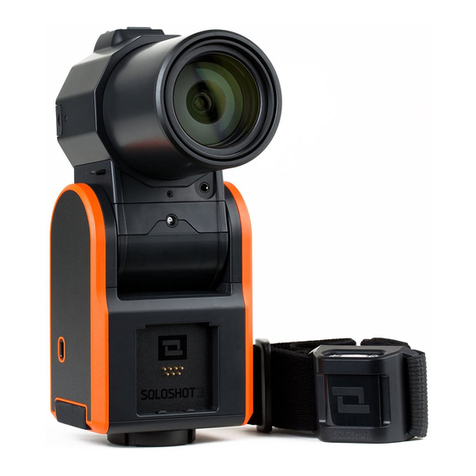
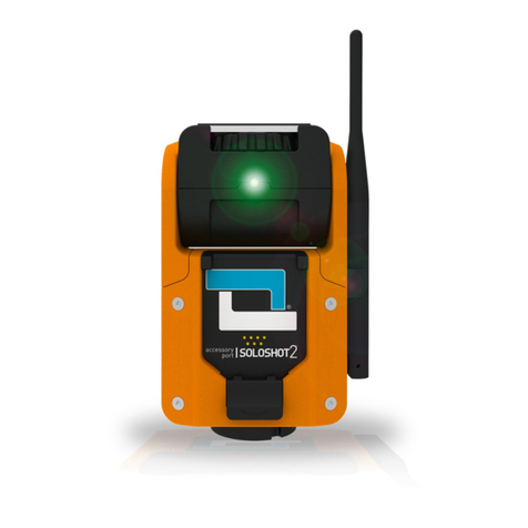
Soloshot SOLOSHOT2 User manual

Camcorder Bundle
- instructions for use -

Step 1.0 | Safety First
Please read the and warnings
carefully before using the product.
SAFETY INSTRUCTIONS
Step 1.1 | Update Firmware
-You must update your firmware. Please do so
now before proceeding with instructions.
Important
Click for firmware update instructions.HERE
Step 1.2 | Connect Base
Connect Base to Tripod.

Step 1.3 | Hand Tighten
Screw the Base onto your tripod until you feel light
resistance from the motor.
Step 1.4 | Tool Tighten
Use Tripod Tool to finish tightening.
Step 1.5 | Attach Camera
Attach your camera to the Base using the mounting screw
and spinning wheel.

Step 1.6 | Align Camera
Make sure your camera points in the same direction as
the tracking LED.
Step 1.7 | Camera Settings
Turn on your CX-240 or CX-405 by opening the screen.
Adjust settings below(click for details):
= Auto.FOCUS
= Active.STEADYSHOT
= Limited by your SD card quality
and size. We recommend 60p.
IMAGE QUALITY
= Turn off.iAUTO
Step 1.8 | Camera Controller
This is your Camera Controller.

Step 1.9 | Multi Cable
This is your Multi Cable for controlling your CX-405/CX-240
camera.
Step 1.10 | Power Cable
This is your Power Cable for powering your CX-405/CX-240
camera.
Step 1.11 | Insert Cables
Open silicone cover on side of your Camera Controller.
Insert the appropriate ends of the Multi Cable and Power
Cable into the Camera Controller.

Step 1.12 | Dock Controller
Dock your Camera Controller into the accessory port on
your Base.
Step 1.13 | Connect Multi
Connect the free end of the Multi Cable to the Multi Port
on your camera.
Step 1.14 | Connect Power
Connect the female end of your Power Cable to the
camera's USB.
Note: SOLOSHOT can only power certain cameras (CX-405
and CX-240).

Travel Tip
IMPORTANT:Unplug all cables from Camera Controller
and camerawhen transporting your SOLOSHOT.
Step 1.15 | Charge Base
Open side flap on Base.
Plug mini USB end of charging cable into side of
Base.
Plug USB end of cable into standard walll adaptor
(included with SONY camcorder).
Plug adaptor into wall socket.
Charging indicator on Base will be RED while
charging and GREEN when ready.
Step 1.16 | Charge Tag
While holding the Tag at a 45-degree angle, dock the
Tag into Accessory Port on Base.
Tag will click into place.
LED above Tag’s power button will turn when
charging and when fully charged.
RED
GREEN
Slide the dock button down to release Tag.
Note: Base must also be plugged in to charge Tag.

Step 2.0 | Base On/Off
Base Power:
On -Press power button.
Off - Press and hold power button for 6 seconds.
Note: LED 3 will only illuminate if Camera Controller
is connected.
Step 2.1 | Tag On/Off
Tag Power:
On - Press power button. LED 1 will turn .RED
Off - Press and hold power button for 6 seconds.

Step 2.2 | LEDs 1-6
The 6 LEDs on your Base representdifferent settings.
Each LED/Setting can be toggled between different
operating modes based on your needs.
LED 1 = Tilt Setting
LED 2 = Trajectory Setting
LED 3 = Zoom Setting
LEDs 4 - 6: SettingsMULTI MODE
Step 2.3 | Change Modes
Change Modes by changing the color of the blinking LED:
Cycle through colors/modes by pressing the M
button.
Step 2.4 | Change Settings
Jump to the next LED/Setting by a quick pressing of the
power button.
The active LED/Settingwill blink.

Step 2.5 | LED 1 | Tilt Setting
Selectyour tilt mode by changing LED 1color based on
your activity's requirements as described below.
LED 1 = GREEN
Surf & Turf Mode:
Great for activities performed on a level surface like
surfing, kiteboarding, soccer and wakeboarding.
is now built into Surf & Turf!JUMP Detection
LED 1 = RED
Big Altitude Mode:
Great for activities with large altitude changes
(Examples: snowboarding andRC planes).
Requireswider framing.

LED 1 = ORANGE
Pan Only Mode:
Lock tilt at a specific angle regardless of Tag
location.
Allows filmmakers to limit motion to a single degree
of freedom.
Also captures tighter shots.
Step 2.6 | LED 2 | Trajectory Setting
Set how long your Base continues to track along it's
trajectory when Tag signal is disrupted.
LED 2 = GREEN
One (1) Second Trajectory :
Use ifwipeouts are most important to you because
your Base will stop tracking shortly after signal loss.
Tradeoff: Tracking may be jumpy at times but you
won't miss the carnage!

LED 2 = RED
Three (3) Second Trajectory :
Use in situations where obstructions or distance
may disrupt the communication link.
Great for filming RC planes from long distances.
LED 2 = ORANGE
Ten (10) SecondTrajectory:
Great for surfing deep barrels so you are still in
frame when you get spit out.
Tradeoff: SOLOSHOT will not stop at point of
wipeout.
Step 2.7 | LED 3 | Zoom Options
Set how tight a frame you want to capture and SOLOSHOT
will automatically zoom your camera in and out to
maintain it.

LED 3 = GREEN
Wide Mode:
Maintains an 80ft wide shot when operating in Surf
& Turf or Pan Only Modes.
Maintains a 125ft wide shot when operating in Big
Altitude Mode.
LED 3 = RED
MediumMode:
Maintains a50ft wide shot when operating in Surf &
Turf or Pan Only Modes.
Maintains a 75ft wide shot when operating in Big
Altitude Mode.
LED 3 = ORANGE
Tight Mode:
Maintains a 30ft wide shot when operating in Surf &
Turf or Pan Only Modes.
Maintains a 45ft wide shot when operating in Big
Altitude Mode.

Step 3.1 | Verify Assembly
If you have not already assembled your Base, Camera
Controller and Tripod as described in Assembly,please do
so now.
Step 3.2 | Choose Location
Choose Tripod and Base location:
At least 30ftback from activity area.
Make sure Tripod and camera are level for best
results.
Step 3.3 | Power Up
Turn on Base and camera:
Press power button on Base.
Open LCD screen to turn on camera.

Step 3.4 | Set Modes
Use the power and M buttons to set your Base to the
desired modes as described in .2.3- 2.5
Step 3.5 | Centering Object
Identify object to center withinyour camera's screen for
calibration:
Surf & Turf -
Object must be at least50ft away and at the level of
your activity surface.
Examples: Surfboard fins at ocean's edge or
intersecting lines on a soccer field.
-Big Altitude
Object must be at least 150ft away but can be at any
level.
Example: Includes fence post on ski slope.
Pan Only-
Object must be at least 50ft away and at any level.
Tip: Adjust tilt using the tilt arrows as needed during
tracking
Note: You canswitch toBig Altitude and Pan Only Modes
at any time during tracking regardless of the calibration
mode and methodused. However, you can only switch
back to Surf & Turf if you originally calibrated in that mode
using a centering object level with the activity surface as
described above.

Step 3.6 | Zoom In
Manually zoom your camera all the way in on the
centering object:
Use pan/tilt arrows on Base to center object as you
zoom in.
Be sure to center the object in the center of the
motor play for best results.
Step 3.7 | Tag Ready
Your Tag should now be warm:
Indicated by Tag LED 1 blinking .RED
Step 3.8 | Tag Walk
Place Tag in palm of hand,white side facing up and
complete warm up by walking around:
or : At least 50 steps.Surf & Turf Pan Only
: At least 150 steps.Big Altitude

Step 3.9 | Button Press 1
Time your walk to end at the Base then immediately:
Hold Tag white side up over your camera.
Press the (+) buttons on both Base & Tag
simultaneously.
Release both (+) buttons.
All 3 Tag LEDs and All 6 Base LEDs will start flashing
.RED
Step 3.10 | Button Press 2
Quickly go to your centering object:
Press Tag (+) buttonto complete calibration.
Step 3.11 | Setup Complete
The tracking LED on your Base will start
continuouslyblinking once your Base and Tag are paired.
GREEN
Indicates the Base is actively tracking the Tag.
LED is highly directional &changes brightness with
distance.
If you can see it, the Base is pointing at you and you
are within range.
Bright sunshine may make it harder to see LED at
longer distances that are still within range.
LED 3 will blink on the Tag indicating that it's being
tracked by the Base.
RED

Step 3.12 | Record Commands
Press and hold your Tag's (+) button to toggle between
Record and Standby.
LED 3 blinking = Record.RED
LED 3 blinking = Standby.GREEN
Step 4.0 | Intro to Multi Mode
LEDs 4, 5 and 6 on your Base control Multi Mode.
See section 4.1to film multiple Tags from a single
Base.
See section 4.7to learn how to film one Tag from
multiple Bases.
See section 4.8to learn how to film multiple Tags
from multiple Bases.

Step 4.1 | Multiple Tags
Multi Mode requires at least TWO Tags.
Purchase Extra Tags individually or use Tags
from another SOLOSHOT2 package or bundle.
HERE
Step 4.2 | Warm Up Tags
Add more Tags to a calibrated and paired Base & Tag
system at any time.
Warm up additional Tagsas describedin step .3.0
Note: You only need to do a walkabout (step )
when using Tag to calibrate a Base.
3.9
Step 4.3 | Add New Tags
Add new Tag to a calibrated & paired system by:
Press and hold the (+) button on the already-paired
Tag OR Base.
Press the (+) button on the new Tag.
IMPORTANT: Order matters. If you make a mistake, use
the (+) button on the remaining Base or Tag component of
the original system to bring the other two components
back in.
Other manuals for SOLOSHOT2
1
Table of contents
Other Soloshot Camera Accessories manuals

