Superb Epsilon SB12V1200Wh-M User manual

Manual
LITHIUM BATTERY
SB12V1200Wh-M
12.8 V/90 Ah/1200Wh
(Lithium Iron Phosphate)
Epsilon

2
User Manual SB12V1200Wh-M Lithium Iron Phosphate battery
Dear customer,
This manual contains all the information necessary to install, use and maintain the Super B
SB12V1200Wh-M Lithium Iron Phosphate Battery. We kindly ask you to read this manual
carefully before using the product. In this manual, the SB12V1200Wh-M battery will be
referred to as: the Li-Ion battery.
This manual is meant for the installer and the user of the Li-Ion battery. Only qualified,
certified personnel may install and perform maintenance on the Li-Ion battery.
Please consult the index at the start of this manual to locate information relevant to you.
This is the original manual, keep it in a safe location!
Copyright©Super B b.v. All rights reserved. Licensed software products are owned by
Super B or its subsidiaries or suppliers, and are protected by national copyright laws and
international treaty provisions. Super B products are covered by Dutch and foreign patents,
issued and pending. Information in this publication supersedes that in all previously published
material. Specifications and price change privileges reserved. Super B is a registered
trademark of Super B b.v.
For more information, or to order documents, contact:
Super B b.v.
Expolaan 50
7556 BE Hengelo (Ov)
The Netherlands
Tel: +31(0)748200010
E-mail: support@super-b.com
www: www.super-b.com

Be in chargeSuper B
3
Table of content
1. Introduction 5
1.1. Product description 5
1.2. Glossary of Terminology 6
1.3. Used symbols 6
2. Product specifications 6
2.1. Product features 6
2.2. General product specifications 7
2.3. Technical specifications 7
2.3.1. Battery/Cell designation 7
2.3.2. Electrical properties 7
2.3.3. Dimensions(LN5) 8
2.4. Environmental conditions 9
2.5. Required tools 9
2.6. Components 10
2.7. Connections, indicators and battery controls 11
2.7.1. J1 / CAN1 (RJ45) 12
2.7.2. J2 Inputs (WR-MPC3 3mm Male Header) 12
2.7.3. J3 Monitor (WR-MPC3 3mm Male Header) 12
2.7.4. J4 Outputs (WR-MPC3 3mm Male Header) 13
2.7.5. J5 / CAN 2 (RJ45) 13
2.7.6. S1 Push button 14
2.7.7. Configuration Switch 14
2.7.8. X1 / X2, Battery terminals 14
2.7.9. Bluetooth 15
2.7.10. LED Indicators 15
2.7.11. Operation modes 16
2.7.12. System components operation modes dependencies 16
2.8. Optional Components 17
3. Safety guidelines and measures 18
3.1. General 18
3.2. Installation 19
3.3. Use 19
3.4. Disposal 19
3.5. Safety symbols and markings on product 20
4. Installation 21
4.1. General information 21
4.2. Unpacking 21
4.3. Preparing the battery for use 21
4.3.1. Placement of the battery 21
4.3.2. Set battery in normal operation mode 21
4.4. Connection wires 21

4
4.4.1. Connecting power cables with automotive type terminals 21
4.4.2. Connecting shrink fit type of power cables 22
4.4.3. Connecting power cables with automotive type terminals and caps 24
4.5. Connecting to the CAN interface (RJ45) 25
4.5.1. Connecting the data cables 26
4.6. Connecting a charger to the battery 27
4.7. Connecting batteries in parallel 27
4.7.1. Connecting BM01 Super B battery monitor (optional) 27
4.8. Disconnecting a battery 29
5. Battery use 30
5.1. General information 31
5.2. Charging 31
5.2.1. Charging rate 31
5.2.2. Charging method 32
5.2.3. Battery balancing 34
5.3 Power saving mode 34
5.4. Battery History Recording 34
6. Inspection, cleaning and maintenance 34
6.1. General information 34
6.2. Inspection 34
6.3. Cleaning 34
6.4. Maintenance 34
7. Storage 35
8. Transportation 35
8.1. General 35
9. Disposal and recycling 36
9.1. General information 36
10. Troubleshooting 37
11. Warranty and liability 38
Appendix I. Declaration of Conformity 40
Appendix II. Certificate of Compliance 42
Appendix III. Performance Graphs 44
Appendix IV. Conductor requirements 45

Be in chargeSuper B
5
1. Introduction
1.1. Product description
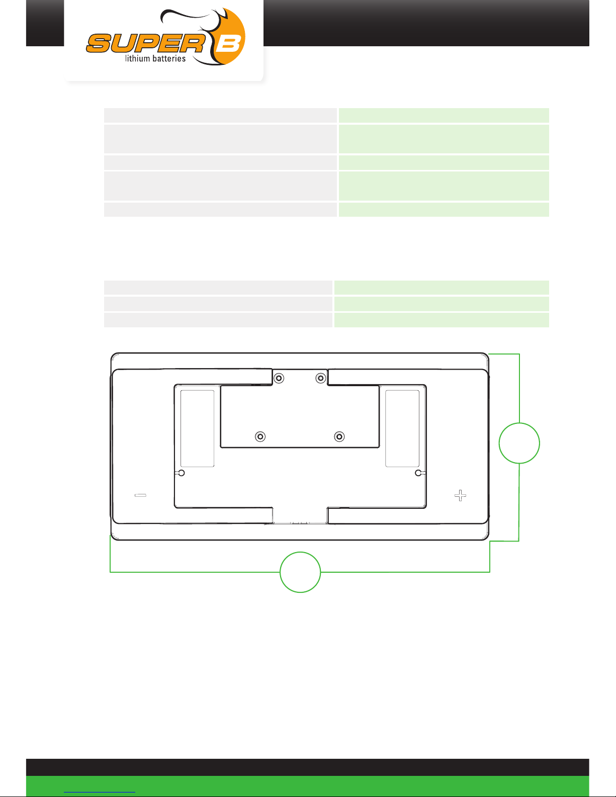
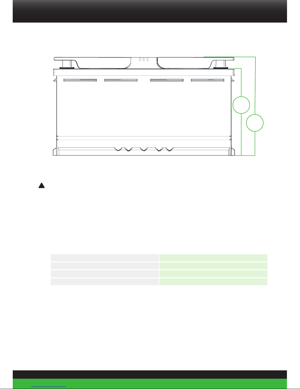
The SB12V1200Wh-M is a Lithium Iron Phosphate rechargeable battery. Potential
applications of this battery include: Recreation vehicles service battery, marine service
battery, energy storage. The boundaries of its use, as described in this manual should always
be upheld. The Li-Ion battery may not be used in medical or in aviation related applications.
The Li-Ion battery may not be used for any purposes other than described in this manual.
Using the battery for any other purpose will be considered improper use and will void the
warranty of the product. Super B b.v. cannot be held responsible for any damage caused
by improper, incorrect or unwise use of the product. Read and understand this manual
completely before using the product.
Super B provides a CE Declaration of Conformity (Appendix I) and a Certificate of Compliance
(Appendix II) for the product. In accordance with CE guidelines, a design and manufacturing
schedule is available. A Material Safety Data Sheet is also available.
The SB12V1200Wh-M complies with the following council directives:
• 2006/66/EC on Environmental EU Compliance
• 2004/108/EC (December 15, 2004) on Electromagnetic Compatibility
The SB12V1200Wh-M complies with the following standards:
• EMC: Emission - EN61000-6-3 (2007) +A1 (2001); Immunity - EN6100-6-2 (2005) + AC (2005)
• IEC 62133, Safety requirements for portable sealed secondary cells, and for batteries made
from them, for use in portable applications
• IEC 62619, SAFETY REQUIREMENTS FOR SECONDARY LITHIUM CELLS AND BATTERIES, FOR
USE IN INDUSTRIAL APPLICATIONS
• UN38.3, Classification procedures, test methods and criteria relating to class 9, Lithium metal
and lithium ion batteries
• IEC 62281, Safety of primary and secondary lithium cells and batteries during transport
During the use of the product, user safety should always be ensured, so installers, users,
service personnel and third parties can safely use the product. The user must always have
access to this manual; keep it in a safe accessible location.

6
1.2. Glossary of Terminology
Endurance Life-cycle: The products maximum lifespan, achieved by adhering to the guidelines
presented in this manual
Charge cycle: A period of use from fully charged, to fully discharged, and fully recharged
again.
SoC: State of Charge
SoH: State of Health
BMS: Battery Management System
VMS: Voltage Management System
EMS: Energy Management System
1.3. Used symbols
The following icons will be used throughout the manual:
!
Warning! A warning indicates severe damage to the user and/or product may occur when a
procedure is not carried out as described.
!
Caution! A caution sign indicates problems may occur if a procedure is not carried out as
described. It may also serve as a reminder to the user.
2. Product specifications
2.1. Product features
• Drop-in replacement for lead acid LN5 batteries
• Traction battery
• Lithium Iron Phosphate (LiFePO4)
-Safe lithium technology
-Superior abuse tolerance
• Maintenance free
• Integrated BMS (Battery-Management system)
• Terminals for 95mm² wire connection / M8 flat terminal with automotive terminal post with
rotation lock
• Integrated protection device for maximum protection and safety
• Safe and protected by integrated protection device
• 2000W/200A continuous discharge
• Peak power (30s) 3500W/350 A
• Fast charging
• Charge current regulator, for safe low temperature charging
• Wireless communication interface: Bluetooth
• Wired communication interfaces: CAN (J1939), LIN (CI-Bus), NMEA2000, CANopen

Be in chargeSuper B
7
• Battery monitoring / History Storage
• Adaptive cell balancing
• Low self-discharge
2.2. General product specifications
Product name: SB12V1200Wh-M
Producer: Super B b.v.
Battery type: Lithium Iron Phosphate (LiFeP04)
Product Lifespan: +/-5 to 10 years or 1000-2000 cycles at 1C charge/discharge or up to
4000 cycles at C3 charge/discharge*
*The lifespan value given above is an indication at 25°C. Battery lifespan depends strongly
on temperature and the applied charging and discharging loads. For more information on the
lifespan of the battery, appendix III may be consulted.
2.3. Technical specifications
Mass: 12.5 kg (+ /- 5%)
Ingress protection rating: IP62
2.3.1. Battery/Cell designation
Battery designation according to IEC 61960: 4IFpR19/67-60
Battery designation according to IEC 62620: IFpR19/67[60p4s]M/-10+60/90
Cell designation according to IEC 62620: IFpR19/67/M/-10+60/90
2.3.2. Electrical properties (25°C)
Open Circuit Voltage 13.2V dc
Nominal voltage 12.8V dc
Rated capacity 90Ah / 1152Wh
Charge method Constant Current - Constant Voltage
Charge voltage 14,2V... 14,8V
End-of-discharge voltage 10V DC
Charge current Max 90A (1C)
Discharge current continuous 200A
Discharge current 30 seconds 350A

8
Discharge current 1 second 600A
Discharge performance at 20 °C (rated
capacity) 90Ah / 1152Wh
Discharge performance at –20 °C (capacity) 59Ah / 755Wh
High rate discharge performance at 20 °C
(capacity) 81Ah / 1024Wh
Short-circuit protection (20ms) 700A
More information on the battery’s performance (cycles) may be found in Appendix III.
2.3.3. Dimensions(LN5)
Height (H): 190 mm
Width (W): 353 mm
Thickness (T): 175 mm
174
+0
mm
-2
353
+0
mm
-2
175
+0
mm
-2

Be in chargeSuper B
9
168
+0
mm
-4
190
+0
mm
-4
2.4. Environmental conditions
!
!
Warning! The Li-Ion Battery may only be used in conditions specified in this manual.
Exposing the battery to conditions outside the specified boundaries may lead to serious
damage to the product and/or the user.
Use the battery in a dry, clean, dust free, well ventilated space. Do not expose the battery to
fire or water or solvents.
When the batteries are placed in an enclosed environment without air circulation, it is
advised to provide 2 ventilation holes of 100mm x 100mm each, to prevent heat built-up.
Operating temperature range -40°C to +65°C*
Storage temperature range -40°C to +65°C
Relative humidity Between 5 and 85 %, non-condensing
Vibrations and shocks According UN38.3 and IEC 6228
* When temperature is < 10ºC or > 45ºC performance will be degraded. (see Appendix III)
2.5. Required tools
• M13 Hexagon socket wrench
• Combined 2.5mm / 6mm Allen hex key (included with battery)

10
2.6. Components
1
2 3 4 5 6 7 8 9 10 11
1. (1x) Super B SB12V1200Wh-M Battery
2. (1x) Tool (combined 2.5mm/6mm Allen
hex key)
3. (2x) Hex bolt M8 x 16mm
4. (2x) Bolt M8 x 20mm
5. (4x) Spring washer M8
6. (2x) Plain washer M8
7. (1x) removable automotive battery pole
positive
8. (1x) removable automotive battery pole
negative
9. (2x) removable handles
10. USB stick (manual)
11. RJ45 CAN Termination resistor

Be in chargeSuper B
11
2.7. Connections, indicators and battery controls
J1 J2 J3 J4
S1 S2
X1
X2
J5
ON
1 2 3 4 5 6 7 8 9
J1: RJ45 (CAN1)
J2: Inputs 4 Pins
J3: Monitor 6 Pins
J4: Outputs 8 Pins
J5: RJ45 (CAN2)
S1: Push Button
S2: Configuration switch
X1: Battery Terminal 1x 95mm2 wire connection or automotive terminal
X2: Battery Terminal 1x 95mm2wire connection or automotive terminal

12
2.7.1. J1 / CAN1 (RJ45)
PIN # Service description Function
1CAN H Communication
2CAN L Communication
3CAN GND Communication
4NC
5NC
6CAN Shield EMC
7NC
8CAN Power Power
Table 1. CAN 1 / J1 interface
2.7.2. J2 Inputs (WR-MPC3 3mm Male Header)
PIN # Service description Range Function
1IN 1A + (0...60Vdc) NA
2IN 1B - NA
3IN 2A + (0...60Vdc) Storage mode
4IN 2B - Storage mode
Table 2. Inputs J2
2.7.3. J3 Monitor (WR-MPC3 3mm Male Header)
PIN # Service description Range Function
1Battery + + (5... 18Vdc) Power
2State of Charge 0...10Vdc SOC Indication
3NC
4NC
5LIN -45...+45Vdc Communication
6Battery - - Power
Table 3. Monitor J3

Be in chargeSuper B
13
2.7.4. J4 Outputs (WR-MPC3 3mm Male Header)
PIN # Service description Range Function
1OUT 1A -60...+60Vdc 100mA (Generator)
2OUT 1B -60...+60Vdc 100mA (Generator)
3OUT 2A -60...+60Vdc 100mA (Inverter)
4OUT 2B -60...+60Vdc 100mA (Inverter)
5OUT 3A -60...+60Vdc NA
6OUT 3B -60...+60Vdc NA
7OUT 4A -60...+60Vdc NA
8OUT 4B -60...+60Vdc NA
Table 4. Outputs J4
2.7.5. J5 / CAN 2 (RJ45)
PIN # Service description Type of signal to the product
1CAN H Communication
2CAN L Communication
3CAN GND Power
4NC
5NC
6CAN Shield EMC
7NC
8CAN Power Power
Table 5. CAN 2 / J5 interface

14
2.7.6. S1 Push button
Service description Type of signal to the product Range
Switch Input High / Low
Table 6. Switch S1
2.7.7. Configuration Switch
For functions see software release document.
Service description Type of signal to the product Range
Switch 1 Input On / Off
Switch 2 Input On / Off
Switch 3 Input On / Off
Switch 4 Input On / Off
Switch 5 Input On / Off
Switch 6 Input On / Off
Switch 7 Input On / Off
Switch 8 Input On / Off
Table 7. Configuration Switch S2
CAN Undefined / Spare Protocol
Switch 1 Switch 2 Switch 3 Switch 4 Switch 5 Switch 6 Switch 7 Switch 8
1Off Off Off - - - - - No
CANopen*
2On Off Off - - - - - J1939
3Off On Off - - - - - CANopen
4Off Off On - - - - - NMEA2000
.
.
.
Table 8. CAN Protocol Configurations (* When CANopen is switched off, battery goes into power saving mode, see chapter 5.3)
2.7.8. X1 / X2, Battery terminals
PIN # Service description Range Function
1Battery - Terminal - Power
2Battery + Terminal + (0...30Vdc) Power
Table 9. Battery terminal interface

Be in chargeSuper B
15
2.7.9. Bluetooth
Service description Type of signal to the product Range
Bluetooth Communication 10 meter
(class 2)
Table 10. Bluetooth
2.7.10. LED Indicators
D2D1 D3
D1 (Green)* D2 (Yellow)* D3 (Red)* Mode
Off Off Off De-energized / shutdown mode
Off Off On Degrade mode (reduced functionality)
On Off Off Normal operation mode
On On Off Warning
On On On Configuration mode
Table 11. LED Mode (* When battery is in idle mode, LED indicator flashes every 3 seconds)

16
2.7.11. Operation modes
Configuring mode
The BMS device can receive, check and take into account additional configuration data sent
by its main EMS/VMS device (master/slave relation).
Normal Operation mode
The device is fully operational. It means that no error is detected and that the device can
execute its Control and Monitoring tasks.
Degraded mode
The BMS device detects either an internal or external failure. If a critical error occurs during
Normal Operation mode, the mode management function goes to Degraded mode.
Shutdown mode
All BMS services are stopped.
De-energized mode
When the battery is in idle mode for a specified time the BMS shuts down all non-essential
electronics to minimize the quiescent current.
2.7.12. System components operation modes dependencies
Operating mode Protective disconnect
device Communication BMS
Configuring mode Open Yes Active
Normal Operation mode Closed Yes Active
Degraded mode Open Yes Active
De-energized mode Open No Inactive
Shutdown mode Open / Closed No Sleep
Table 12. System components operation modes dependencies

Be in chargeSuper B
17
2.8. Optional Components
Description Article name Manufacturer Manufacturer
code Super B code
4 pins 3 mm
plug
WR-MPC3, Single Row
Female Receptacle
Housing, 4 pins,
(3.00mm) WR-MPC3
micro power connector
(4 positions)
Würth Elektronik
GmbH & Co
662 004 013 322 4200 000 0006 0
6 pins 3 mm
plug
WR-MPC3, Single Row
Female Receptacle
Housing, 6 pins,
(3.00mm) WR-MPC3
micro power connector
(6 positions)
Würth Elektronik
GmbH & Co
662 006 013 322 4200 000 0005 0
8 pins 3 mm
plug
WR-MPC3, Single Row
Female Receptacle
Housing, 8 pins,
(3.00mm) WR-MPC3
micro power connector
(8 positions)
Würth Elektronik
GmbH & Co
662 008 013 322 4200 000 0004 0
3 mm pins
WR-MPC3, Male Crimp
Terminal, (3.00mm)
WR-MPC3 micro power
connector contact crimp
Pin
Würth Elektronik
GmbH & Co 662 002 137 22 4200 000 0007 0
RJ45 cable SB RJ45 cable 1 m 4200 000 0003 0
RJ45
termination
resistor
SB RJ 45 CAN
terminator Epsilon Super B 4200 000 0001 0
Battery
monitor SB BM01 12-24V Super B 9586 100 3119 0
BM01 Epsilon
Cable SB BM01 cable Epsilon Super B 4200 000 0002 0
Table 13. Optional components that can be used with the Li-Ion battery

18
3. Safety guidelines and measures
3.1. General
• Do not dismantle, open or shred secondary cells or batteries.
• Do not expose cells or batteries to heat or fire. Avoid storage in direct sunlight.
• Do not short-circuit a cell or a battery. Do not store cells or batteries haphazardly in a box or
drawer where they may short-circuit each other or be short-circuited by other metal objects.
• Do not remove a cell or battery from its original packaging until required for use.
• Do not subject cells or batteries to mechanical shock.
• In the event of a cell leaking, do not allow the liquid to come in contact with the skin or eyes.
If contact has been made, wash the affected area with copious amounts of water and seek
medical advice.
• Do not use any charger other than that specifically provided for use with the equipment.
• Observe the plus (+) and minus (–) marks on the cell, battery and equipment and ensure
correct use.
• Do not use any cell or battery which is not designed for use with the equipment.
• Do not mix cells or batteries of different manufacture, capacity, size or type within a device.
• Battery usage by children should be supervised.
• Seek medical advice immediately if a cell or a battery has been swallowed.
• Always purchase the battery recommended by the device manufacturer for the equipment.
• Keep cells and batteries clean and dry.
• Wipe the cell or battery terminals with a clean dry cloth if they become dirty.
• Secondary cells and batteries need to be charged before use. Always use the correct
charger and refer to the manufacturer’s instructions or equipment manual for proper
charging instructions.
• Do not leave a battery on prolonged charge when not in use.
• After extended periods of storage, it may be necessary to charge and discharge the cells or
batteries several times to obtain maximum performance.
• Retain the original product literature for future reference.
• Use only the cell or battery in the application for which it was intended.
• When possible, remove the battery from the equipment when not in use.
• Dispose of properly.
!
Warning! Keep the battery away from water, dust and contamination.

Be in chargeSuper B
19
!
Warning! Do not crush or puncture the battery.
!
Warning! Never touch the battery contacts or allow (conductive) objects to touch the
contacts.
3.2. Installation
!
Warning! 12V systems only. Never use the Li-Ion battery in systems with batteries in series.
!
Caution! Do not reverse connect the power cables (polarity)
3.3. Use
!
Warning! Do not overcharge the Li-Ion battery.
!
Warning! Never short circuit the battery.
!
Caution! This product can store fault conditions internally, like excessive charge current or
deep discharge situations. Super B uses this information in the warranty process.
!
Caution! Do not operate battery beyond published maximum specifications.
!
Caution! In case of an under-voltage shutdown, charge immediately.
!
Warning! Always remain within the limits indicated in paragraph 2.3.2 during the use of the
Li-Ion battery.
3.4. Disposal
Dispose of the battery in accordance with local, state and federal laws and regulations.
Batteries may be returned to the manufacturer.
Do not mix with other (industrial) waste.

20
3.5. Safety symbols and markings on product
Several safety symbols and markings can be found on the product. These markings are
displayed below. Never remove these markings!
The meanings of the symbols:
Shield eyes
Note operating instructions
Battery acid
Explosive gas
No smoking, no naked flames, no sparks
Keep away from children
Dispose of the Li-Ion battery in accordance with local, state and federal laws and
regulations. Batteries may be returned to the manufacturer. Do not mix with other
(industrial waste)
This product, or sections of this product can be recycled
14340_067_id_SUPB_Labels_Safety_30x70.indd 126-04-17 09:27
Other manuals for Epsilon SB12V1200Wh-M
1
Table of contents
Other Superb Camera Accessories manuals

Superb
Superb NOMIA 12V100Ah User manual

Superb
Superb NOMIA 12V340Ah User manual

Superb
Superb NOMADA 12V105Ah User manual

Superb
Superb SB12V100E-ZC User manual

Superb
Superb NOMIA 12V160Ah User manual

Superb
Superb Epsilon SB12V1200Wh-M User manual

Superb
Superb MASON 12V20Ah User manual

Superb
Superb SB12V160E-ZC User manual

Superb
Superb NOMIA 12V210AH User manual

Superb
Superb SB12V2600P-AC User manual