SoloStrength Ultimate Series Instruction Manual


3
Thank you for purchasing the SoloStrength Lifestyle Package. Whether you intend to use our adaptable tness
support system for personal use, or for the training and rehabilitation of others, we encourage you to read
the complete Owner’s Manual and Instruction Guide before getting started. We also suggest that you register
online, at www.SoloStrength.com,to stay up-to-date on all activities, accessories and promotions for your
SoloStrength System. Finally, please review our limited liability statement (found at the end of this document,
in our instruction guide, and on our website), which states that SoloStrength is not responsible for any injury
or damage resulting from misuse.
This system is everything you need to maintain your own balanced workout program. Regardless of age,
gender or tness level, you can target key muscle groups in both your upper and lower body. Whether your
goal is weight loss, body sculpting, healthy living or increased energy, SoloStrength can help you succeed.
Strength training not only tones and conditions the muscles you use every day to stand, walk, lift and turn, it
can actually transform your body composition. By decreasing the proportion of body fat and increasing the
proportion of lean muscle, strength training can turn up your metabolic thermostat, allowing you to burn more
calories all the time, even at rest.
Read through the Owner’s Manual carefully.
It is the authoritative source for information about your SoloStrength System. To start developing a full body
conditioning program that works for you, please see the instruction guide and online video tutorials.
SoloStrength is not intended for use by children under 12 years old, and all minors should be supervised by
an adult while using the system to ensure proper use and safety.
To ensure that it is safe for you to exercise on your Solostrength (or any other equipment), we recommend
that you consult a doctor. While the SoloStrength SpeedFit and Lifestyle Package provides a comprehensive
guide for safe movements, you may also benet from consulting a personal trainer or physiotherapist about
customized programs. For other inquiries on how to get the most out of your SoloStrength, please email our
professional trainers or visit our website.
Your SoloStrength Package includes instructional video access online which will be provided by email. If
codes.
If you have questions about your SoloStrength please call Customer Service toll free at: 1-866-454-SOLO
(North America Toll Free, or 1.604.818.6225 Intl.), Monday through Friday, 9:00 AM to 5:00 PM, Pacic Time.
Congratulations on purchasing your new
SoloStrength Ultimate Series Total Body Gym!

4
Setup and Maintenance of your SoloStrength Ultimate System 4
Safety Instructions & Labels 4 - 5
Warnings 5 - 6
Product Specications 6
Box Contents 7
Assembly Manual (ULTIMATE Main/Doorway/Freestanding/Corner/Wall) 8-10
Inspection, Maintenance & Storage 11
Accessories 11
Warranty 12
Regulation Information 13
Disclaimer 13
Table of Contents
Setup and Maintenance of your SoloStrength Ultimate System
•
•
•
•
•
•
•
•
•
Please read through instructions before beginning, and ensure all parts are laid out. If you discover any de-
for assistance.
During assembly, you may require use of a small amount of lubrication (some provided or common multi-use
silicone base spray such as wd-40) to t snug metal pieces together and inside the main slider channel.
A durable coated surface on all metal parts has been used to protect the look and function of your system.
Avoid scratching surface and contact with sharp or foreign metal objects.
Do not allow more than one person to hang on the support bar at one time. Do not bounce or stand on the bar.
Only apply weight to the bar when it is level and the handles are locked on each side. Handles are not locked
until the security rings (or grooves) are fully exposed on the bar.
There is ample room in the slider and slider channel to allow for some freedom and ease of movement while
adjusting the bar height. Do not force the bar to slide if stuck or lodged, gently attempt to level the bar out of
the jam and continue.
While adjusting the bar height, ensure that the locking pins are pulled completely back to keep the pins from
knocking on the inside of the slider channel and damaging the nish on your system.
SoloStrength is intended for indoor use, or covered outdoors. It is recommended to keep your system out of
direct sunlight for extended periods, high humidity or wet environments. If set outdoors, we recommend a
covered roof or gazebo of your deck or outdoor living area. UV damage or discoloring of certain components
may occur if directly exposed to the sun.
To limit resistance on the sliding mechanisms, we recommend applying a small amount of silicone based
lubrication inside the channels to keep the adjustments smooth and quiet. The lubrication is included in
the package. Common sprays such as WD40 are okay. Please note maintenance notes in this manual.
We recommend keeping the bar set to highest level to avoid accidents when not in use.
Safety Instructions and Lables
1.
BEFORE PLACING WEIGHT ON THE HORIZONTAL SUPPORT BAR, ENSURE THAT THE BAR IS SET
LEVEL, AND THE OVAL SPRING HOLES ARE SHOWING BY THE ORANGE PULL FLANGES, INDICATING
THAT THE PINS ARE LOCKED INTO THE SUPPORT HOLES. (Continued on the next page)

5
Safety Instructions and Labels
(Continued)
Warnings
2.
3.
4.
5.
6.
DO NOT SWING YOUR BODY ON SOLOSTRENGTH SYSTEMS.
AT NO TIME IS IT SAFE TO USE SOLOSTRENGTH AS A SWING BAR, IT IS MEANT AS SUPPORT FOR
FULL OR PARTIAL BODYWEIGHT TO EXECUTE ONLY THE SUGGESTED ACTIVITIES IN THE SPEEDFIT
PROGRAM GUIDE THAT COMES WITH THIS PACKAGE. ALL OTHER ACTIVITIES ARE DONE SO AT THE
USERS OWN RISK AND ARE NOT RECOMMENDED.
CRUSH HAZARD, KEEP HANDS CLEAR OF SLIDERS DURING USE AND FRAME WHILE FOLDING FOR
STORAGE OR TRANSPORT.
KEEP HAIR, FINGERS, LOOSE CLOTHING, PETS AND CHILDREN AWAY FROM MOVING PARTS TO AVOID
SERIOUS INJURY. ALSO BE SURE TO HAVE ALL PINS LOCKED IN PLACE BEFORE GETTING ON YOUR
SOLOSTRENGTH SYSTEM.
KEEP THE INSIDE RAILS FREE OF DUST AND DEBRIS. THERE MAY BE A NEED FROM TIME TO TIME
TO CLEAN THE INSIDE OF RAILS AND SLIDER GUIDE AND REAPPLY A SMALL AMOUNT OF GREASE TO
ENSURE SMOOTH SLIDING AND THIS SHOULD BE PART OF A REGULAR MAINTENANCE PROGRAM.
DUE TO THE INTENSITY OF ENGAGING IN FULL BODY EXERCISE AND RESISTANCE ACTIVITY, IT
IS RECOMMENDED TO START MUCH LIGHTER AND EASIER THAN YOU THINK YOU CAN HANDLE
COMFORTABLY AT FIRST, AS SOME MUSCLE TIGHTENING AND POSSIBLY SORENESS MAY RESULT
FROM RUSHING AND PUSHING YOURSELF TOO QUICKLY, PARTICULARLY DURING THE FIRST FEW
WEEKS OF USE.
Always use SoloStrength in the tone and manner in which it is instructed in the program guide. Because of
the versatility and many possibilities that an adjustable support bar oers, the owners/users must accept all
responsibilities for injury which may result from misuse.
Do not swing yourself or anyone else on your support bar or frame. Tipping hazard exists with misuse.
Before beginning this or any exercise program, consult a physician or health professional, who can assist
you in planning a program appropriate for your age and physical condition. This is especially important if you
are over age 35 or have pre-existing health problems.
Do not overexert yourself. Stop exercising immediately and consult your doctor if you experience pain or
tightness in your chest, irregular heartbeat, shortness of breath, or if you feel faint, nauseous, or dizzy.
This product is designed for home and commercial use, built to exceed commercial grade quality and
durability standards. While the support bar is tested to over 1000 lbs static weight, maximum single person
weight capacity for exercise movements is suggested at 300 Lbs. Use only as instructed.
Inspect your system before each use to ensure proper operation. Do not use this equipment unless all
moving parts are working properly. See details on inspection, maintenance and storage.
Ensure there is no debris under the frame or support feet of your SoloStrength System. If debris is under
foot pads (doorway and wall mount), or support feet (freestanding), damage to hard oor may result.
Use only the accessory items recommended by the manufacturer.
(Continued on the next page)

6
Product Specications
(Patents pending in U.S.A, Canada and Internationally)
*Bar static weight capacity tested over 1000 lbs.
Your SoloStrength Package includes assembly and instructional video access online.
www.solostrength.com
To avoid serious injury, care should be taken at all times when getting on and o this or any exercise equipment.
Product Warning Label:
Warnings
(Continued)
• Failure to follow safety instructions stated in owner’s manual may result in serious injury or death
• Keep children away. Not for use by children under age 12 ( over 12 only with supervision )
• Obtain a medical exam before beginning exercise program
• Inspect machine before use and refrain from use if the machine appears damaged or inoperable
• Pinching hazard in moving parts and during folding
• DO NOT swing or stand on the bar, use only as directed in manual
• Maximum individual user weight of 300 Lbs
• Refer to owner’s manual for more information
WARNING
Bar inner grip width: 33.5” | Commercial grade construction | Maximum user weight 300 lbs.
Overall dimension:
L x W x H: 4.0” x 41.0”x 86.5 (82.5)”
Weight: approx. 31.5 lbs
Fits standard door widths (28”-36”)
Corner mounting brackets optional
•
•
•
•
86.5”
ULTIMATE 87 and 83
WALL MOUNT SYSTEM
(OPTIONAL)
ULTIMATE DIP/Row BAR
(OPTIONAL)
12” Height Extensions
(OPTIONAL)
82.5”
41.0”
41.0”
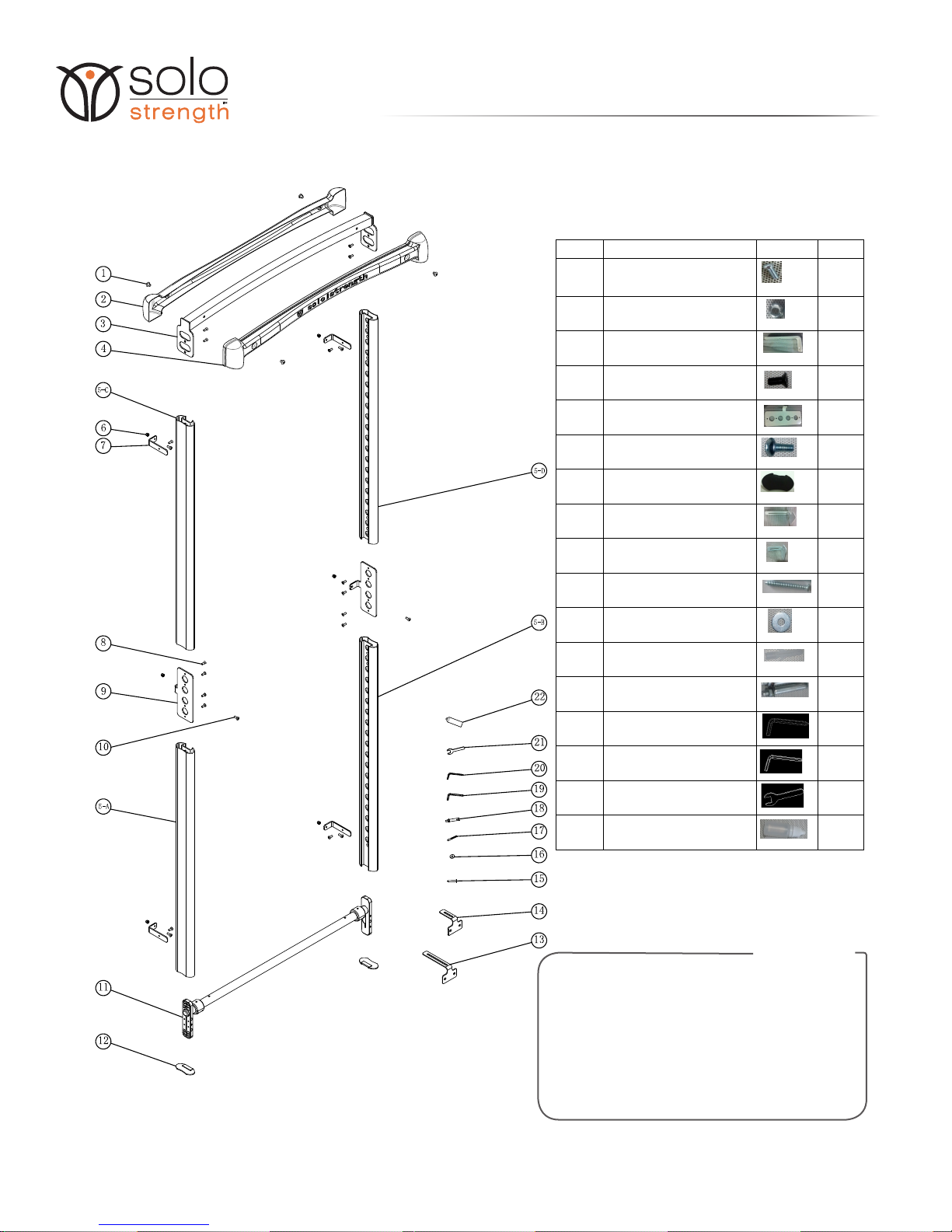
BOX CONTENTS
7
SPEEDFIT ULTIMATE 87/83
(HARDWARE)
PART NO. PART NAME PICTURE
Q'TY(PCS)
1 Allen pan-headed bolt 4
6 Nylon nut 6
7 Connection piece(Small) 4
8 Allen countersunk bolt 16
9 Connection piece(Big) 2
10 Allen pan-headed bolt 6
12 Foot pad 2
13 L shaped clip (Big) 6
14 L shaped clip (Small)(tight corner) 3
15 Countersunk self tapping screw 12
16 Washers 12
17 Plastic nail (wall mount -drywall) 12
18 Expansion bolt (wall mount -concrete) 12
19 Allen wrench + cross head 1
20 Allen wrench 1
21 Solid wrench 1
22 lubricant 1
*Includes extra parts for variations.
**Freestanding, Wall Mounted, and Corner
installations do not use all hardware.
8
ASSEMBLY MANUAL
ULTIMATE MODELS 87/83
*********************************************RESOURCES******************************************
Visit www.solostrength.com/assembly-tips/ for any updates to these instructions and
tips to assist in a quick and successful installation. Some videos are available.
If you experience difculty you can always reach our Customer Service with your
questions and we will be happy to assist.
*******************************************************************************************************
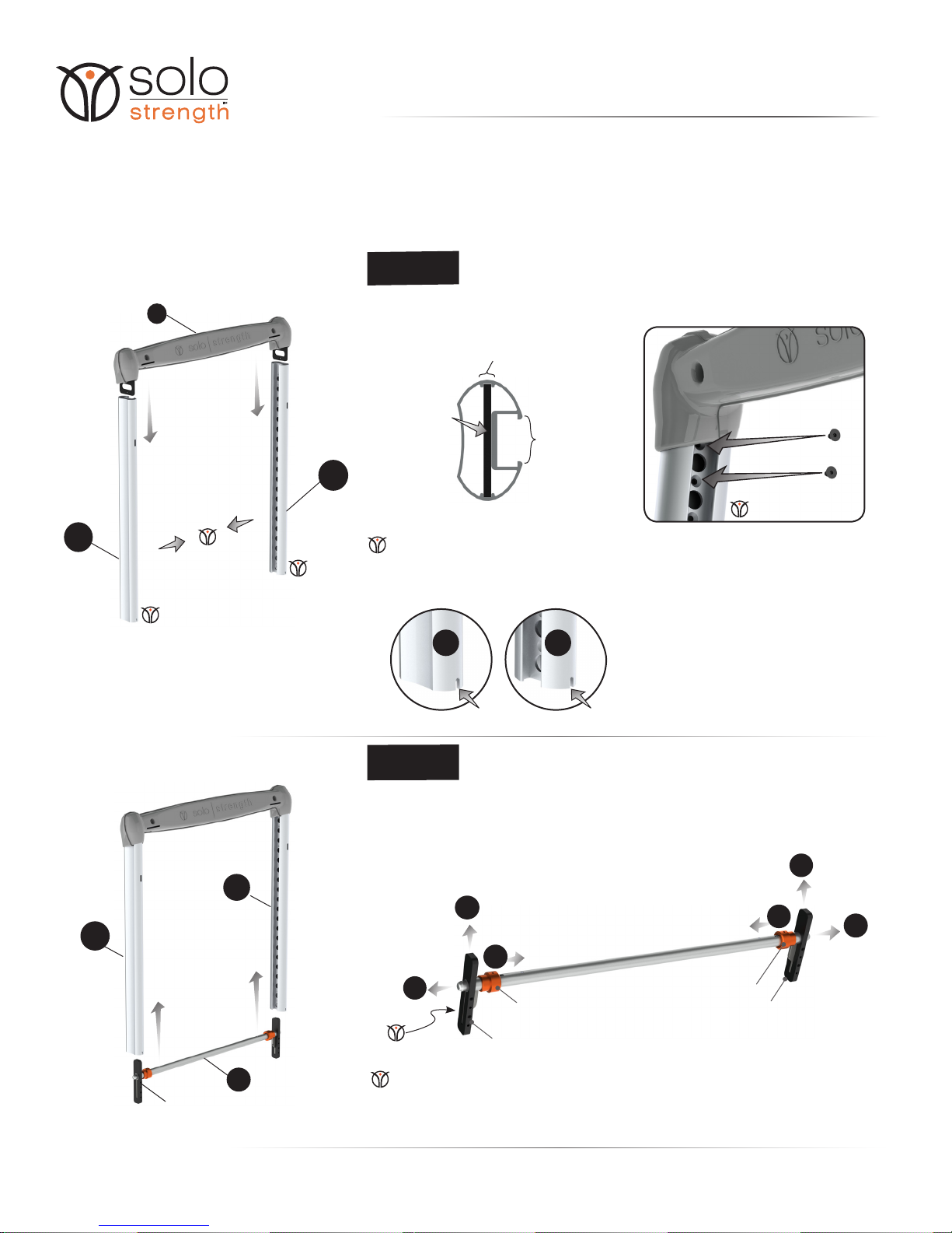
5-D 5-C
NOTCH NOTCH
INTERIOR CHANNEL
METAL PLATE
EXTERIOR CHANNEL
STEP 1
Check Point 1: Be sure that the screw head is ush with the extrusion. If not,
Part 11 (Bar Assembly) will not slide up and down smoothly.
Check Point 2: Exterior channels should face inward.
Check Point 3: Notch in Items 5-D & 5-C should be located at the bottom.
Ater assembling the header with parts # 1, 2, 3, & 4, begin by facing the back side.
Slide plates of assembled header into the interior channels in Items 5-C & 5-D.
Install two 1/4” screws (part #8) on each side.
•
•
•
Backside View.
Countersunk sides
facing inward
2
5-D
•Slide Part 11 as shown.
A: Retract both handles by pulling them rmly toward the center.
B: Insert Part 11 into exterior channels of Items 5-C & 5-D.
C: Release handles so that both ends of the bar t into the holes found
in the exterior channels.
STEP 2
C
C
A
A
B
B
HANDLE
HANDLE
Check Point 1: The long end of the black components (slider) should point downward.
Check Point 2: Apply some of lubriction provided (or silicone spray lube like WD-40)
on the outer surface of the sliders to help slide freely up and down.
11
5-D
5-C
SLIDER
SLIDER
5-C
Ensure screws on side
of sliders are tightened.
9
ASSEMBLY MANUAL
ULTIMATE MODELS 87/83
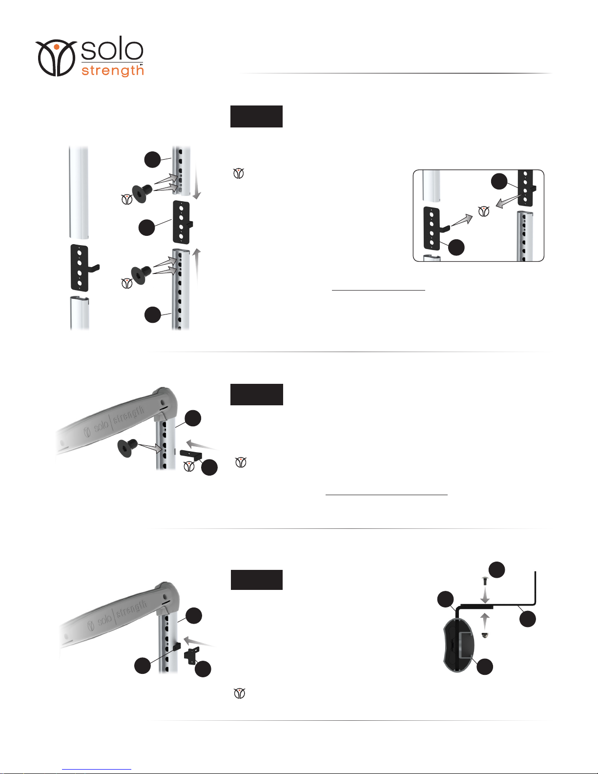
•
•
Slide part# 9 into parts 5-A & 5-C, and install 1/4” screws (part #8) as shown on the left.
Repeat on the opposite side with 5-B & 5-D.
STEP 3
Check Point 1: Be sure that the screw head is
ush with the extrusion. If not,
Item 2 will not move smoothly.
Check Point 2: The bent tab on Part #9
should both face inward.
Check Point: The bent tab on part #7 should face inward.
•
•
Insert part# 7 into the slots in part # 5-A, B, C, D.
Install 1/4” screw. See the illustration on the left as an example. Look to the exploded
view in Box Contents, page 7, for the location of all four slots (two on the top, two on
the bottom).
STEP 4
•
•
•
Attach part # 13/14 to the previously-installed part#
7 using parts # 6 & 10. Do not fully tighten; let part#
13 move freely. Refer to the cross section diagram
on the right.
Repeat this in the remaining ve locations where
part # 7&13 were installed.
Install foot pad (part # 12) to protect oors.
STEP 5
5-C
Check Point: FOR TIGHTER CORNERS AROUND FRAME USE SHORTER
L-BRACKETS (PART # 14).
9
5-A
5-C
7
5-C
713
7
13
5-C
10
9
9
CONGRATULATIONS!
IF YOU PURCHASED A FREESTANDING SYSTEM YOU ARE NOW COMPLETE
THIS STAGE. BEGIN ASSEMBLING THE BASE NOW. KEEP 2 SETS OF OF PARTS
#10 & 6 HANDY FOR THE FINAL STEP OF FREESTANDING BASE CONNECTION.
*You will have extra parts that are for Doorway/Wall-Mounted/Corner installations.
CONGRATULATIONS!
IF YOU PURCHASED A WALL MOUNT/CORNER SYSTEM YOU ARE NOW
COMPLETE THIS STAGE. IT’S TIME TO ADD THE INSTALLATION BRACKETS.
*You will have extra parts that are for Doorway System.
10
ASSEMBLY MANUAL
•
•
•
•
•
•
•
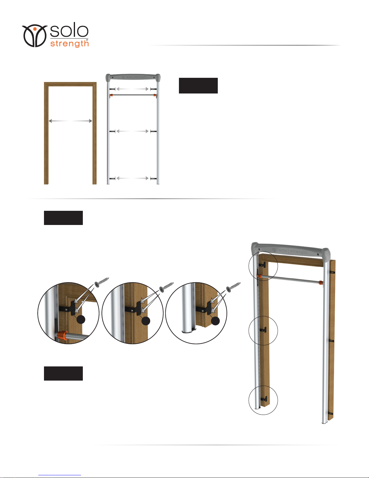
STEP 7
STEP 8
•
•
•
Measure the inside width of the door frame.
Loosely adjust part# 13 to the door frame width.
OPTIONAL: for tighter corners/wall space, use part #14 on one side.
IMPORTANT:
Step 7 below, start by setting bar in second lowest hole to square
the system.
When centered and squared in front of door, place the brackets to
the frame as squared and at as possible, hand tighten the screw
and nuts to hold in position. Then, use ONE screw on the middle
right anchor point. This allows for ne tuning adjustments as
needed.
Run the bar up and down to ensure it’s smooth, when bar is locked
in lower holes, screw in top right then top left screws.
STEP 6
WIDTH
DOOR FRAME
ADJUST
Place unit in front of the door frame.
Adjust part # 13 (Door Frame Brackets-long) as needed to ensure that door frame
brackets are placed tight against the door frame. Check all six locations.
TIP: Slide the exercise support bar up and down freequently to space system.
Ensure that unit is centered with respect to the door frame and at to oor.
Install two wood screws per part # 13 (14 optional) in three locations as shown.
Repeat on the opposite side.
Powerdrill is recommended for best results. Not provided.
Tighten all six nut sets the connect parts # 7 & 13 that were loosely installed in Step 5.
YOU’RE FINISHED!
ULTIMATE MODELS 87/83
13 13 13

11
INSPECT YOUR SOLOSTRENGTH ULTIMATE GYM PRIOR TO EACH USE
Before beginning your workout session, be sure to make the following inspection:
To view the latest accessories to use with your SoloStrength System, please visit our website at
www.SoloStrength.com to register your email address to be notied of new accessories and special promotions.
ROUTINE MAINTENANCE
Make sure all the screws and bolts are securely in place and the support bar is level and locked into
position. Handles are not locked until the security rings (or grooves) are fully exposed on the bar.
Check that the support bar is traveling correctly in the groove on each side and free of resistance.
•
•
Wipe down your SoloStrength System on a regular basis using a clean cloth and light soapy solution. Do
not leave wet towels or workout clothing laying or hanging on the equipment.
Periodically check the slider(s) for signs of wear, and all check to tighten all locking screws and bolts.
Contact SoloStrength if any damage is noticed and don’t use the systme until that part is replaced.
If debris should cause resistance in the channel of your SoloStrength and its sliding function, use a
disposable towel to wipe clean the channels and the sliders, and re-apply a small amount of lubrication
inside the sliding channel on each side of the SoloStrength structure.
Silicone or lithium based spray is preferred lubricant the unit. Multi purpose 3-in-1 oil or machine oil can
also be used to lubricate the springs in locking pins and channels. Small amounts only are helpful for
optimal function..
•
•
•
•
Inspection, Maintenance & Storage
Accessories

12
Dedication to Quality
SoloStrength Lifestyle Products warrants this product to be free from all
defects in material and workmanship when used
according to the manufacturer’s instructions.
See Limited Warranty Card or website for more details.
www.SoloStrength.com
If you have any comments or questions contact our
Customer Service Department, toll free at 1-866-454-SOLO
Monday through Friday, 9:00 am to 5:00 pm, Pacic Time
Please record the following information and keep for reference.
Serial #: ______________________________
Date Of Purchase: ______________________
Save your sales receipt.
(You may wish to staple it into this manual.)
Warranty

13
Your SoloStrength is commercial grade for private and commercial use. These products are built to industrial
grade standard, and greatly exceeds the quality standards for consumer grade products. For use in home, oce,
tness facilities, common area living facilities, clinics and studios. Covered outdoors with limited humidity is
acceptable. Warranties dier for various applications. Using SoloStrength for purposes not expressly outlined
in the user and instructional manuals may void warranty. Any changes or modications not expressly approved
by SoloStrength could void the user’s authority to operate this device and warranty. Please consult website for
updated information. www.SoloStrength.com. There are no serviceable parts included. Using SoloStrength
for any reason other than expressly displayed may result in serious harm or damage.
This program is fully protected under the laws of copyright and trademark. Any unauthorized duplication,
exhibition, distribution or other use of this program, or any part thereof, without written prior consent is strictly
forbidden by law, including Canadian National and United States Federal law. Violators will be prosecuted
to the maximum extent of the law. Important cautions: Please note the following important cautions before
using this product. Not all exercises are suitable for everyone and this or any exercise program may result
in injury. Consult with your doctor before embarking on this or any other exercise program, or if discomfort
is experienced following activity. To reduce the risk of injury, never force or strain during exercise. If you
experience pain or discomfort during exercise, stop immediately and consult your doctor. Begin slowly during
each of the activities and limit the bounce in the movements. Certain special cautions apply to this or any
other exercise program. For example, women who are menstruating should not practice inverted poses, back
bends, or vigorous standing poses. Pregnant women should not practice twists or any abdominal tightening
poses or activity while laying on their back. Other special cautions may apply to individuals with specic
health issues. For that reason, you should consult your doctor to nd out if special restrictions apply to you.
You may nd more information by visiting us at www.SoloStrength.com for knowledge base of general health,
parenting and children’s health, disease or injury recovery or sports specic training. The creators, producers,
performers, participants and distributors of this product cannot guarantee that this program is safe and proper
for every individual. For that reason, this program is sold without warranties or guarantees of any kind. The
SoloStrength System is built for home use “to commercial standards” and is covered by manufacturer lifetime
warranty for parts and function. Any liability, loss or damage in connection with any use of this program or the
SoloStrength system, including but not limited to any liability, loss or damage resulting from the performance of
activities demonstrated in this program or shared through our website (www.solostrength.com) or its aliates,
or the advice and information given here, is expressly disclaimed.
©2007-2017 SoloStrength Lifestyle Products Corp.
All rights reserved. Designed and partially made in North America, manafactured in China for
SoloStrength Lifestyle Products Corp. All rights reserved.
SoloStrength SpeedFit Lifestyle Program ®is a registered trademark.
U.S.A, Canada, and International Patents Pending.
No part of this booklet may be reproduced or utilized in any form,
by any means, electronic, mechanical or otherwise, without the expressed
written consent of the copyright holder.
Regulatory Information
Disclaimer

14
N O T E S

Table of contents


