Solutronic Energy GridManager User manual
User Manual GridManager
with FEED-IN function
User manual GridManager with FEED-IN function
MoS/MM/JK 2016-11-23 Version: A8, Subject to change without prior notice

GM_User Manual_A8_EN
User Manual GridManager with FEED-IN function
2.1 Aim of this manual...............................................................................................................
2.2 Scope.................................................................................................................................
2.3 Target group...................................................................................................................
2.4 Explanation of the symbols and associated terms used............................................
2.5 Abbreviations....................................................................................................................
3.1 Safety in general..............................................................................................................
3.2 Intended use.......................................................................................................................
9.1 LED power..........................................................................................................................
9.2 LED L1, L2, L3..............................................................................................................
9.3 LED error.........................................................................................................................
11.1 IP-address GridManager..................................................................................................
11.2 Total AC power of connected inverters...........................................................................
11.3 Minimum withdrawal from grid / Maximum feed in to the grid..............................
11.4 Additional settings.............................................................................................................
12.1 Activating FEED-IN mode.................................................................................................
12.2 Assigning phases L1 L2 L3...........................................................................1.................
12.3 UDP-Port (Parameter are not active).........................................................................
12.4 Fallback.........................................................................................................1.
12.5 Using more than one GridManager................................................................................
12.6 Verifying communication...............................................................................................
Contents
Contents
3 Safety..................................................................................................................................
4 Prerequisites..............................................................................................................................
5 Mode of Operation..............................................................................................................
6 Installation GridManager 63........................................................................................................
7 Installation GridManager 250................................................................................................
8 Connecting GridManager, inverters and PC1...............................................................................
9 Operating status............................................................................................................................
10 Data connection to GridManager using SOLPLUS+...........................................................
11 Parameter settings GridManager............................................................................................
12 Parameter settings Inverter.......................................................................................................
13 Measurement readings GridManager..................................................................................
14 Attachment..............................................................................................................................
14.1 Example.........................................................................................................................
1 Notes about the User Manual...................................................................................................
2 Notes about this manual........................................................................................................
1
1
1
1
1
1
3
4
4
4
5
6
7
9
11
12
12
12
12
13
14
14
15
16
19
21
21
22
22
23
24
25
26
27
27

GM_User Manual_A8_EN 1/28
12.1 Activating FEED-IN mode.................................................................................................
12.2 Assigning phases L1 L2 L3...........................................................................1.................
12.3 UDP-Port (Parameter are not active).........................................................................
12.4 Fallback.........................................................................................................1.
12.5 Using more than one GridManager................................................................................
12.6 Verifying communication...............................................................................................
1 Notes about the User Manual
Dear Customer,
Thank you for buying a GridManager with FEED-IN function designed and manufac-
tured by Solutronic Energy. This manual describes how to use your GridManager with
FEED-IN function. Please keep it somewhere where you have ready access to it
whenever you need to. Please comply at all times with the safety precautions we refer
to in this manual. Please be advised in all cases the security precautions referred to in
this document.
2 Notes about this manual
2.1 Aim of this manual
This manual will help you to carry out installation work on your inverter quickly and
safely. Please read this chapter thoroughly and carefully. It contains some important
tips on how to use this manual.
2.2 Scope
This User Manual applies to the Solutronic GridManager with FEED-IN function.
2.3 Target group
All service work on SOLPLUS inverters must be performed by a fully qualified
electrician who has completed the technical training offered by Solutronic. The fitter
must have the necessary certification and authorisation of the responsible power
utility.
2.4 Explanation of the symbols and associated terms used
2.4.1 Explanation of the symbols used for safety instructions
Please read and observe the following safety instructions in this manual.
The danger classes describe the risks of non-observance of the safety instructions.
(The safety instructions describe the following danger classes per ANSI.)
Notes about the User Manual

GM_User Manual_A8_EN2/28
Attention!
“Attention!" denotes a warning that, if not observed, can result in property
damage!
Warning!
"Warning!" denotes a warning that, if not observed, can result in death or
serious injury!
"Danger!" denotes a warning that, if not observed, will result in death or
serious injury!
Useful information and tips to help you operate the GridManager to best
effect.
Caution!
"Caution!" denotes a warning that, if not observed, can result in personal
injury!
Danger!
Note
Description of the Nameplate
Notes about this manual
GM_User Manual_A8_EN 3/28
2.5 Abbreviations
The following abbreviations are used in this manual:
SOLPLUS+ =
=
Read-out and monitoring software for use with all Solutronic
inverters
DC Direct current (direct voltage): electrical value on the input side of
theinverter
=
=
AC
PV
Generator
Photovoltaic
=
GM GridManager with FEED-IN function
Alternating current (alternating voltage): electrical
value on the output side of the inverter
=Solar generator: interconnection of several solar modules to
form a string or a number of parallel strings
Notes about this manual

GM_User Manual_A8_EN4/28
Warning!
Improper use of these devices, non-observance of the warnings given in this
manual and improper tampering with the safety functions can lead to property
damage, personal injury, electric shock and, in extreme cases, death.
Danger!
High voltage due to incorrect connection! Risk of fatal or bodily injury from
electric shock.
3 Safety
3.1 Safety in general
Please read the following safety information and instructions before you put the
GridManager with FEED-IN function into operation for the first time, in order to avoid
personal injuries and/or property damage. These instructions must be complied with
at all times.
If you are not able to understand the language used in this documentation sufficiently,
please contact and inform the supplier of the situation.
Do not try to attempt to install or put the GridManager with FEED-IN function into
service until you have read through all the documentation supplied thoroughly.
Solutronic Energy shall accept no liability for damages resulting from non-observance
of the warnings given in this User Manual.
If you sell on, hire out or pass on this device to someone else in some other way,
make sure that you give the new user these safety instructions, too. Trouble-free and
safe operation of the GridManager with FEED-IN function presumes proper,
professional and workmanlike transportation, storage, mounting and installation as
well as careful operation and thorough maintenance.
3.2 Intended use
This device must be used only for the purpose described in this User Manual:
accessory for use in grid-connected photovoltaic installations.
All safety regulations must be complied with. All installation work must be carried out
precisely as described in this manual. No modification of any kind to or in this device
or to its external wiring is permitted. Any such modification could lead to serious
safety problems and danger to life and limb.
Safety
GM_User Manual_A8_EN 5/28
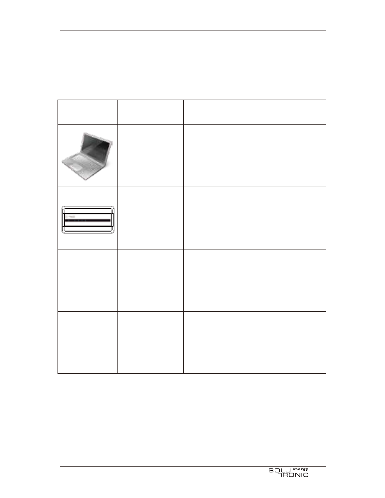
Laptop or PC death.
with SOLPLUS+
professional
GridManager 63 or
GridManager 250
Switch
SOLPLUS 25-55:
SOLPLUS 80-120:
SE 40S2-SE 60S2:
Firmware
Firmware
Firmware
Preferably one with option
to ground the shield of
cables
V2.67.2 or higher
V1.49.13 or higher
V2.2.7
Firmware V1.4.9 or higher
For setting up the
GridManager. Not required
for operation.
V 2.7.4
or higher
4 Prerequisites
The inverters and the GridManager should be connected in one Ethernet using a
dedicated switch for this setup. Using RS485 for regulation is not possible.
Abbildung Bezeichnung Beschreibung
Inverter
Inverter
Inverter
Prerequisites
GM_User Manual_A8_EN6/28
The energy provider requires a temporary power reduction of the installation:
The inverters are regulated to produce no more power than the current allowed
amount plus the current consumption.
The connected power is generally limited: The inverters are regulated to produce
no more power than the allowed amount plus the current consumption.
There is no feed in allowed / required: The inverters are regulated to produce no
more power than the current consumption minus a small margin for regulation.
5 Mode of Operation
The GridManager covers the power management of the inverter as a function of local
consumption.
It’s located between the SOLPLUS inverters and appliances; and the power meter.
The typical reaction time for power regulation is 4 Milliseconds.
If e.g. a maximum of 70% of the installed DC power may be fed in but refrigerator,
lights etc. are switched on. The consumption of these is added to the 70% and allows
the inverter to produce more power to compensate for this.
Potential uses for GridManager:
Mode of Operation
GM_User Manual_A8_EN 7/28
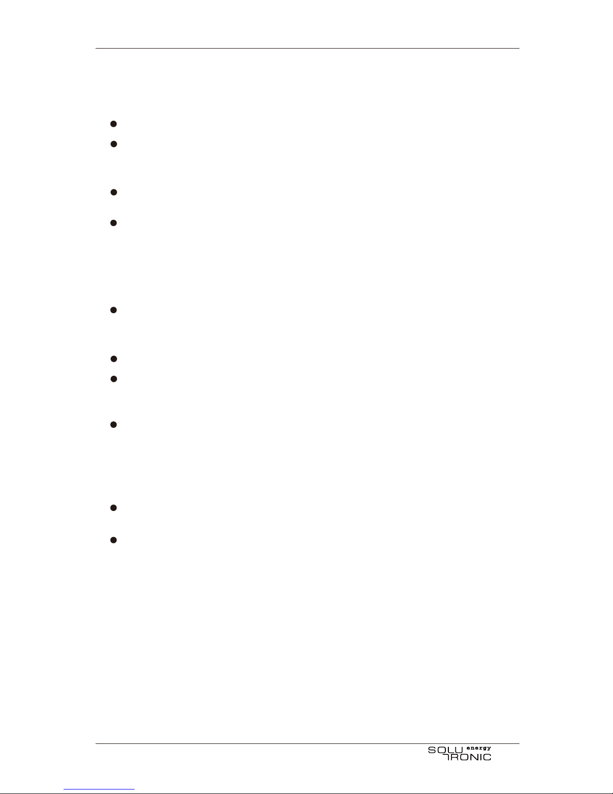
6 Installation GridManager 63
Connection
3x 230 Volt, N, PE, 50 Hertz, max. 63 Ampere per Phase
It shall be installed between the meter (reference counter when feed in is zero
or bidirectional meter when grid-feed is limited) and the local distribution for
appliances and PV-inverter
You may install either a GridManager or a PowerReductionCard, installing both
at the same installation will not work.
Connect appliances to the same phase as the inverter, especially if only one
inverter is used.
Installation
AC-voltage measurement and power supply
The grid voltages L1, L2 and L3 and neutral line N are connected to the green
4-pin connector at the bottom side. L3 and N (230 V AC, 50 Hz) are used to
supply the GridManager. Wire cross-section 1,5 mm².
Check for correct phasing
For overall one phase operation connect the one phase used to all 3 pins L1,
L2 and L3 of the 4-pin connector for voltage measurement. This can be
achieved by bridging all 3 pins.
For correct display of the measured voltages connect ground to the GridMan-
ager. This is best done on the shield of the Ethernet connector. However, the
GridManager will regulate fine without ground connected.
AC-current measurement
The power lines have to be separated on terminals and routed from the
bottom-up through the current transformers of the GridManager.
Wire cross-section 16 mm² (max.) for GridManager 63
Check for correct phasing
Installation GridManager 63
GM_User Manual_A8_EN8/28
L1
L2
L3
N
SLS*Z2*
*If available/required
Note
PE connections not shown!
Installation schematic
House distribution,fuses etc.
Light etc.
Appliance 1-Phase
Appliance 1-Phase
Appliance 3-Phase
Stove
one or more 1-phase
or 3-phase inverter
~
=
Z1*
Yield counter
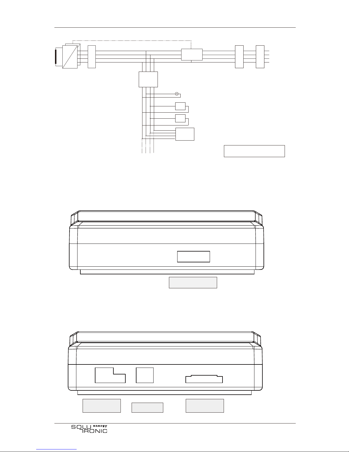
Ethemet-connection Grid-connection
of building
Lower side: power cable input, voltage measurement and N
Upper Side: Ethernet, power cable outlet
Installation GridManager 63
power cable input
CAN cable &
ground cable
voltage
measurement
Ethernet
GM
Two-way
counter
Load
isolator
N L1 L2 L3
N L1 L2 L3

GM_User Manual_A8_EN 9/28
7 Installation GridManager 250
Connection
3x 230 Volt, N, PE, 50 Hertz, max. 250 Ampere per Phase
Use only the approved current transformers type JS24S-250/1A class 1,0 that
were delivered with the GridManager 250
It shall be installed between the meter (reference counter when feed in is zero
or bidirectional meter when grid-feed is limited) and the local distribution for
appliances and PV-inverter
You may install either a GridManager or a PowerReductionCard, installing both
at the same installation will not work.
Installation
AC-voltage measurement and power supply
The grid voltages L1, L2 and L3 and neutral line N are connected to the green
4-pin connector at the bottom side. L3 and N (230 V AC, 50 Hz) are used to
supply the GridManager. Wire cross-section 1,5 mm².
Check for correct phasing
For correct display of the measured voltages connect ground to the GridMan-
ager. This is best done on the shield of the Ethernet connector. However, the
GridManager will regulate fine without ground connected.
AC-current measurement
The power lines have to be routed through the external current transformers of
the GridManager. Watch for correct current flow direction on the current
transformers.
Wire cross-section 240 mm² (max.) for GridManager 250
Check for correct phasing
Last
L1 L2 L3 N
L1 L2 L3 N
Netz
S1 S2 S1 S2 S1 S2
Sensor1 Sensor2 Sensor3
Installation GridManager 250
Stromsensor
Eingange
Anschlussbild GML 250A
Ansicht von Oben Version A1/2014-09-24 ASL
Ethernet
PC /
LAN
CAN
(Option)
Sicherung
NETZ
3 * 230V AC
Sicherung
Sicherung
GML 250A

GM_User Manual_A8_EN10/28
View from top:
Connector for current transformers
L3 L2 L1
S2 S1 S2 S1 S2 S1 Ethernet
Installation GridManager 250
GM_User Manual_A8_EN 11/28
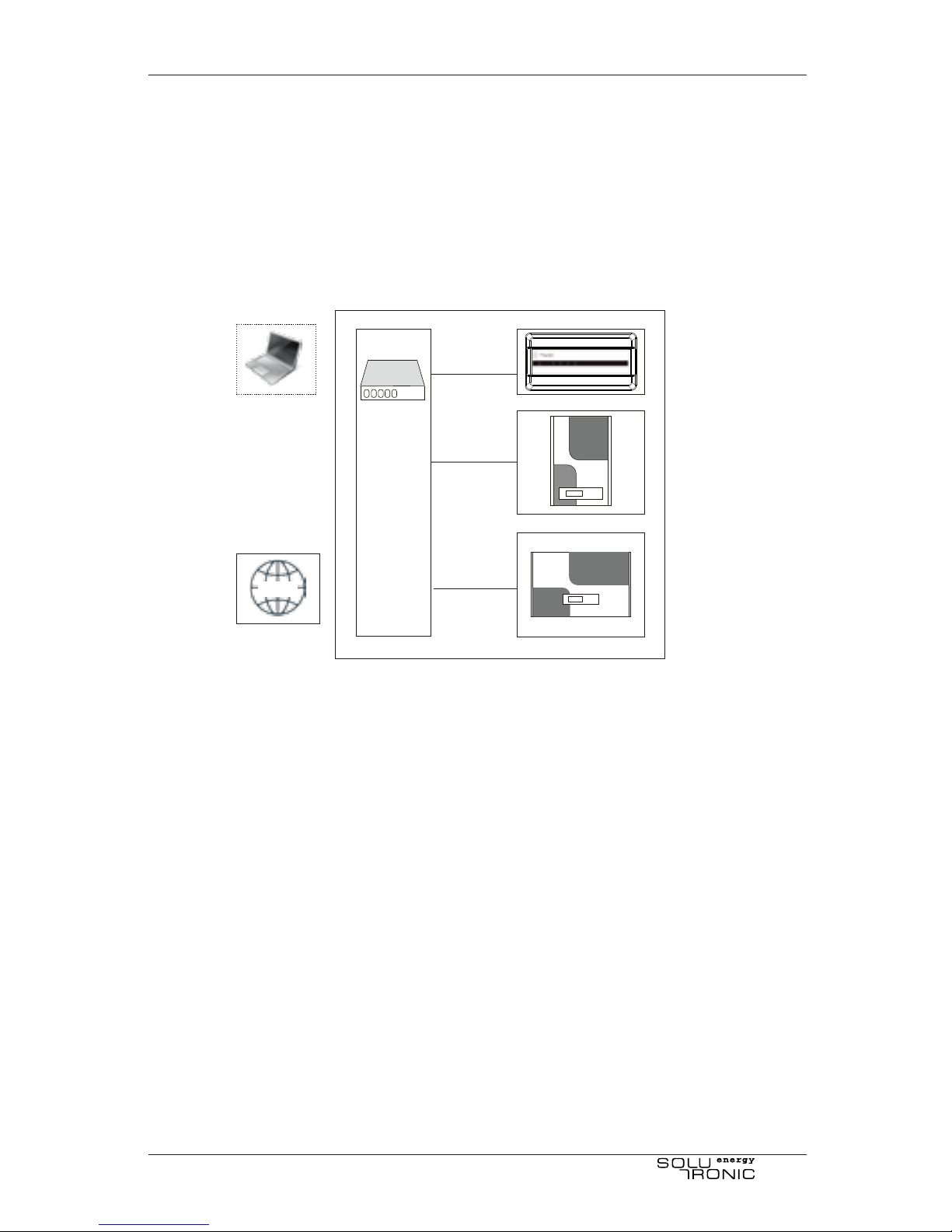
8 Connecting GridManager, inverters and PC
All devices are connected using a standard ethernet-switch and -cables.
The GridManager itself has no display. In the first 60 seconds after starting up the
GridManager uses always the IP-address 192.168.0.98. If a connection to this address
is established, the GridManager will continue to use this IP-address, otherwise it will
switch to the set IP-address after these 60 seconds.
Switch
GridManager
Inverter
Inverter
WWW
Connecting GridManager, inverters and PC

GM_User Manual_A8_EN12/28
9 Operating status
The operating status of GridManager is shown by LEDs.
Operating status
9.1 LED power
State Meaning
Off No power or not yet initialized
On Everything okay
Flashing slowly Internal error found or Default-communication
Flashing fast Operation with default communication parameters
9.2 LED L1, L2, L3
State Meaning
Off No mains voltage on this phase
On UAC okay
Flashing slow UAC not okay
Flashing fast
9.3 LED error
State Meaning
Off No power or not yet initialized
Flashing slow Warning pending or default communication
Flashing fast
Frequency not okay
(only if UAC okay, otherwise slowly flashing LED)
Blink code shows error list. Also the LED flashes
with a frequency of 2 Hz. After this there will be a
break of 3 seconds and then the blink code will be
repeated.

GM_User Manual_A8_EN 13/28
SOLPLUS+ and it’s manuals are available on our homepage www.solutronic-en-
ergy.de. Please use the latest version available, at least the version stated in
chapter 4. To setup the GridManager you’ll need the professional version of
SOLPLUS+. If you need a professional key, please contact our service.
Note
In“Administration” of SPLPLUS+you may add the GridManager like a inverter in a
plant using“TCP/IP individual” as connection type.
For the first setup set your PC to the IP-address 192.168.0.10 and use this data in
SOLPLUS+ to create a new inverter (=GridManager):
(Default) IP-address: 192.168.0.98
SPP-Address (=Serial number): see the silver serial sticker on the GridManager
10 Data connection to GridManager using
SOLPLUS+
Data connection to GridManager using SOLPLUS+

GM_User Manual_A8_EN14/28
GridManager uses the same password mechanics as a inverter. You will need
your individual password level 3 to setup the parameters. Please see the
manual for password level 3 on how to get and enter a password level 3.
Note
11 Parameter settings GridManager
11.1 IP-address GridManager
The IP-address is defined in 4 parameters, each representing a octet of a complete
IP-address.
The 1st segment of the IP address using the format 192.xxx.xxx.xxx
Parameter 110:
Menu:
Default setting:
Password-level:
IP address HH (octet 1)
Communication/WEB
192
1
Parameter 111:
Menu:
Default setting:
Password-level:
IP address HL (octet 2)
Communication/WEB
168
1
The 2nd segment of the IP address using the format xxx.168.xxx.xxx
Parameter 112:
Menu:
Default setting:
Password-level:
IP address LH (octet 3)
Communication/WEB
0
1
The 3rd segment of the IP address using the format xxx.xxx.0.xxx
Parameter 113:
Menu:
Default setting:
Password-level:
IP address LL (octet 4)
Communication/WEB
98
2
Parameter settings GridManager

GM_User Manual_A8_EN 15/28
11.2 Total AC power of connected inverters
These parameters define how much inverter AC power is connected to the 3 phases L1,
L2 and L3.
Add up the maximum output of all connected inverters. Maximum parameter value is
320000 W. If one phase is not connected to a inverter enter 0 (zero) on this phase.
The 4th segment of the IP address using the format xxx.xxx.xxx. 98
To use DHCP enter 0 (zero) in all 4 parameters 110-113. The GridManager will receive
a IP-address from the DHCP server. If no DHCP server is present the default
IP-address 192.168.0.98 is used.
However. for use with SOLPLUS+ we suggest using a fixed IP-address to avoid
changes in the administration.
(Not changeable up to Version 1.09. Make sure no other applications use this port) This
port is used for broadcasting the control signal to the inverters. If you change this
parameter, you need to change the parameter “network port for UDP packages” on the
inverters also.
Parameter:
Menu:
Default setting:
Password-level:
Network Port for UDP packages
Options
33010
2
Parameter 390:
Menu:
Unit:
Accuracy:
Default value:
Password level:
AC total power inverter L1
Options
W
1 W
5000 W
3
Parameter 391:
Menu:
Unit:
Accuracy:
Default value:
Password level:
AC total power inverter L2
Options
W
1 W
5000 W
3
Parameter settings GridManager

GM_User Manual_A8_EN16/28
These parameters will be ignored if parameter 409 “Presetting accumulating
grid-feed” is used.
Note
11.3 Minimum withdrawal from grid / Maximum feed in to
the grid
These parameters define how much power per phase should be either
-withdrawn from the grid in case of zero feed in
or
-fed into the grid in case of power reduction
11.3.1 Minimum withdrawal from grid (Zero Feed-in)
These parameters define how much power should be withdrawn from the grid. For
each inverter add 50 W with a total minimum of 100 W. This will prevent any feed in to
the grid, as there is always a small amount of consumption.
Positive values define the withdrawal. Maximum value is 320000 W
Parameter 392:
Menu:
Unit:
Accuracy:
Default value:
Password level:
AC total power inverter L3
Options
W
1 W
5000 W
3
Parameter 397:
Menu:
Unit:
Accuracy:
Default setting:
Password level:
Minimum removal of grid-total L1
Options
W
1 W
100 W
3
Parameter settings GridManager

GM_User Manual_A8_EN 17/28
These parameters will be ignored if parameter 409 “Presetting accumulating
grid-feed” is used.
Note
While the parameter name says “removal” these parameters can also be used for
limiting the feed in power.
Note
11.3.2 Limited allowed feed in into the grid (single phases)
These parameters define how much power is allowed to be fed into the grid. Each
phase is defined for itself, watch for total limits of feed in.
Negative values define the allowed feed in. Minimum value is -320000 W
Parameter 398:
Menu:
Unit:
Accuracy:
Default setting:
Password level:
Minimum removal of grid-total L2
Options
W
1 W
100 W
3
Parameter 399:
Menu:
Unit:
Accuracy:
Default setting:
Password level:
Minimum removal of grid-total L3
Options
W
1 W
100 W
3
Parameter settings GridManager

GM_User Manual_A8_EN18/28
11.3.3 Limited allowed feed in into the grid (all phases)
This parameter defines how much power is allowed to be fed into the grid in total.
Power is calculated for all three phases simultaneously.
Positive values define the allowed feed in. Maximum value is 320000 W
Parameter 397:
Menu:
Unit:
Accuracy:
Default setting:
Password level:
Minimum removal of grid-total L1
Options
W
1 W
100 W
3
Parameter 398:
Menu:
Unit:
Accuracy:
Default setting:
Password level:
Minimum removal of grid-total L2
Options
W
1 W
100 W
3
Parameter 399:
Menu:
Unit:
Accuracy:
Default setting:
Password level:
Minimum removal of grid-total L3
Options
W
1 W
100 W
3
Parameter 409:
Menu:
Unit:
Accuracy:
Default setting:
Password level:
Presetting accumulating grid-feed
Options
Watt
1 W
0 W
3
Parameter settings GridManager
Table of contents
Popular Inverter manuals by other brands

Westerbeke
Westerbeke 4KW-7.7KW-11KW-12 5KW Operator's manual

Minarik
Minarik MM30000 Series user manual

Kaco
Kaco blueplanet 3.0 TL3 M2 WM OD IIG0 operating instructions

Veichi
Veichi AC100-T3-1R5G manual

Westerbeke
Westerbeke 15.0BTD60-HERTZ Operator's manual

SCS Sentinel
SCS Sentinel SolarGate AAM0095 Installation and user manual


