Solvimus MBUS-GEB User manual

MBUS-GEB -USER MANUAL
solvimus GmbH –Ratsteichstr. 5 –98693 Ilmenau –Germany
Phone: +49 3677 7613060 –Fax: +49 3677 7613069 –E-mail: info@solvimus.de
...we solve. www.solvimus.de
MBUS-GEB
GATEWAY FOR
SMART METERING
Version: 1.32
Date: 2019-12-12
Author:
Tobias Braune
solvimus GmbH
Ratsteichstr. 5
98693 Ilmenau
Germany

MBUS-GEB - User manual
Page 2/45 Version: 1.32 Tobias Braune, 2019-12-12
MBUS_GEB_UG_EN_1.32 (1).docx Released © solvimus GmbH
This page intentionally left blank.

MBUS-GEB - User manual
Tobias Braune, 2019-12-12 Version: 1.32 Page 3/45
© solvimus GmbH Released MBUS_GEB_UG_EN_1.32 (1).docx
Table of contents
1General hints and conventions....................................................................................................................................6
1.1 About this document.............................................................................................................................................6
1.2 Legal bases .................................................................................................................................................................6
1.2.1 Copyright ..........................................................................................................................................................6
1.2.2 Personnel qualifications .............................................................................................................................6
1.2.3 Technical condition of specified devices............................................................................................6
1.3 Symbols........................................................................................................................................................................6
1.4 Font conventions.....................................................................................................................................................7
1.5 Number notation.....................................................................................................................................................7
1.6 Safety guidelines......................................................................................................................................................7
1.7 Scope.............................................................................................................................................................................8
1.8 Abbreviations............................................................................................................................................................8
1.9 Versions........................................................................................................................................................................8
2General information .........................................................................................................................................................9
2.1 Device variants..........................................................................................................................................................9
2.2 Connectors .............................................................................................................................................................. 10
2.3 State LEDs................................................................................................................................................................. 11
3Bringing into service...................................................................................................................................................... 12
3.1 Network configuration and first steps......................................................................................................... 12
3.1.1 Network parameters ................................................................................................................................. 13
3.1.2 Connectivity test (ping) ........................................................................................................................... 14
3.1.3 Web access (HTTP) ..................................................................................................................................... 14
3.1.4 File access (FTPS)......................................................................................................................................... 14
4Configuration.................................................................................................................................................................... 16
4.1 Tab General ............................................................................................................................................................. 16
4.2 Tab Meter ................................................................................................................................................................. 17
4.3 Tab Configuration ................................................................................................................................................ 19
4.4 Tab Server ................................................................................................................................................................ 20
4.5 Tab Security............................................................................................................................................................. 21
4.6 Tab User .................................................................................................................................................................... 21
4.7 Tab Service............................................................................................................................................................... 23
4.8 Print page................................................................................................................................................................. 24
5Specification of the BACnet protocol .................................................................................................................... 25
5.1 Implemented services ........................................................................................................................................ 25
5.2 Supported BACnet interoperability building blocks (Annex-K) ...................................................... 25
5.3 Supported standard BACnet object types ................................................................................................ 25
5.3.1 Meter values.................................................................................................................................................. 25
5.3.2 BACnet device object ............................................................................................................................... 26

MBUS-GEB - User manual
Page 4/45 Version: 1.32 Tobias Braune, 2019-12-12
MBUS_GEB_UG_EN_1.32 (1).docx Released © solvimus GmbH
6Acquisition and processing of meter data........................................................................................................... 27
6.1 Meter configuration............................................................................................................................................. 27
6.1.1 Scanning for meters (M-Bus) ................................................................................................................. 27
6.1.2 Automatic acquisition of meters (wM-Bus)..................................................................................... 27
6.1.3 Configure meters directly ....................................................................................................................... 27
6.2 Format of meter data.......................................................................................................................................... 28
6.2.1 Predefined types for media, measurements and units ............................................................. 28
7Troubleshooting.............................................................................................................................................................. 32
7.1 Hardware errors..................................................................................................................................................... 32
7.1.1 The device does not respond................................................................................................................ 32
7.1.2 Current consumption is too high ........................................................................................................ 32
7.2 Network errors ....................................................................................................................................................... 32
7.2.1 No network connection........................................................................................................................... 32
7.2.2 The MBUS-GEB cannot be accessed via HTTP or FTP................................................................. 33
7.2.3 User does not have write access to the website........................................................................... 33
7.2.4 The web session is terminated unexpectedly ............................................................................... 33
7.2.5 FTPS log-in fails............................................................................................................................................ 33
7.3 Error in meter reading......................................................................................................................................... 34
7.3.1 M-Bus meters cannot be read out....................................................................................................... 34
7.3.2 wM-Bus meters cannot be read out................................................................................................... 34
7.3.3 Not all meters can be found................................................................................................................... 34
7.3.4 M-Bus meters are found but do not have any data on the website .................................... 35
7.3.5 wM-Bus meters are found but do not have any data on the website ................................ 35
7.3.6 Scanning takes a lot of time................................................................................................................... 35
7.3.7 The device restarts occasionally while performing a scan....................................................... 35
7.3.8 Error message: Capacity of internal webserver exceeded ....................................................... 36
7.4 Error in transmitting meter data .................................................................................................................... 36
7.4.1 Meter data is not transmitted via BACnet/IP.................................................................................. 36
8Advanced Features......................................................................................................................................................... 38
8.1 Firmware update................................................................................................................................................... 38
8.1.1 Upload of a firmware image file........................................................................................................... 38
8.1.2 Performing the firmware update......................................................................................................... 38
8.2 Command line interface (CLI).......................................................................................................................... 38
8.2.1 solcmd command reference ................................................................................................................. 39
8.3 Administrative FTP connection...................................................................................................................... 39
8.4 Configuration files ................................................................................................................................................ 40
8.4.1 System configuration file ........................................................................................................................ 40
8.4.2 Meter configuration file ........................................................................................................................... 42
9Technical data................................................................................................................................................................... 44

MBUS-GEB - User manual
Tobias Braune, 2019-12-12 Version: 1.32 Page 5/45
© solvimus GmbH Released MBUS_GEB_UG_EN_1.32 (1).docx
9.1 General characteristics ....................................................................................................................................... 44
9.1.1 Physical dimensions / weight................................................................................................................ 44
9.1.2 Installation / Storage................................................................................................................................. 44
9.1.3 Customs declaration ................................................................................................................................. 44
9.2 Electrical characteristics..................................................................................................................................... 44
9.2.1 Power supply................................................................................................................................................ 44
9.2.2 Meter interfaces........................................................................................................................................... 44
9.2.3 Communication interfaces..................................................................................................................... 44
9.2.4 Galvanic isolation........................................................................................................................................ 44
9.3 Further characteristics........................................................................................................................................ 45
9.3.1 Processing unit ............................................................................................................................................ 45

MBUS-GEB - User manual
Page 6/45 Version: 1.32 Tobias Braune, 2019-12-12
MBUS_GEB_UG_EN_1.32 (1).docx Released © solvimus GmbH
1General hints and conventions
1.1 About this document
This manual provides guidance and procedures for a fast and efficient installation and start-up of
the units described in this manual. It is imperative to read and carefully follow the safety guidelines.
1.2 Legal bases
1.2.1 Copyright
This manual, including all figures and illustrations, is copyright-protected. Any further use of this
manual by third parties that violate pertinent copyright provisions is prohibited. Reproduction,
translation, electronic and phototechnical filing/archiving (e.g. photocopying) as well as any
amendments require the written consent of solvimus GmbH.
Non-observance will involve the right to assert damage claims.
The solvimus GmbH reserves the right to provide for any alterations or modifications that serve to
increase the efficiency of technical progress. All rights arising from the granting of patents or from
the legal protection of utility patents are owned by the solvimus GmbH. Third-party products are
always mentioned without any reference to patent rights. Thus, the existence of such rights cannot
be excluded.
1.2.2 Personnel qualifications
The use of the product described in this manual requires special personnel qualifications. All
responsible persons have to familiarize themselves with the underlying legal standards to be
applied, i. e.:
•Valid standards
•Handling of electronic devices
The solvimus GmbH does not assume any liability whatsoever resulting from improper handling
and damage incurred to both, solvimus own and third-party products, by disregarding detailed
information in this manual.
1.2.3 Technical condition of specified devices
The supplied components are equipped with hardware and software configurations, which meet
the individual application requirements. Changes in hardware, software and firmware are permitted
exclusively within the framework of the various alternatives that are documented in the specific
manuals. The solvimus GmbH will be exempted from any liability in case of changes in hardware or
software as well as to non-compliant usage of components.
Please send your request for modified and new hardware or software configurations directly to the
solvimus GmbH.
1.3 Symbols
Danger: Always observe this information to protect persons from injury.
Warning: Always observe this information to prevent damage to the device.
Attention: Marginal conditions that must always be observed to ensure smooth and
efficient operation
ESD (Electrostatic Discharge): Warning of damage to the components through electrostatic
discharge. Observe the precautionary measure for handling components at risk of
electrostatic discharge.
Note: Make important notes that are to be complied with so that a trouble-free and efficient
device operation can be guaranteed.

MBUS-GEB - User manual
Tobias Braune, 2019-12-12 Version: 1.32 Page 7/45
© solvimus GmbH Released MBUS_GEB_UG_EN_1.32 (1).docx
Additional informations: References to additional literature, manuals, data sheets and
internet pages.
1.4 Font conventions
Names of paths and data files are marked in italic-type. According to the system, Slashes or
Backslashes are used.
i. e.:
D:\Data\
Menu items are marked in italic-type, bold letters.
i. e.:
Save
Sub-menu items or navigation steps within a web browser are marked by using an arrow between
two menu items or tabs.
i. e.:
File
→
New
Pushbuttons or input fields are marked with bold letters.
i. e.: Input
Keys are marked with bold capital letters within angle brackets.
i. e.: <F5>
The print font for program codes is Courier.
i. e.: END_VAR
Names of variables, designators and configuration fields are marked in italic-type.
i. e.:
Value
1.5 Number notation
Numbers are noted according to this table:
Number code
Example
Note
Decimal
100
Normal notation
Hexadecimal
0x64
C Notation
Binary
'100'
in quotation marks
'0110.0100'
nibbles separated with dot
Table 1: Numbering systems
1.6 Safety guidelines
All power sources to the device must always be switched off before carrying out any
installation, repair or maintenance work.
Replace any defective or damaged devices/modules (i. e. in the event of deformed contacts), as the
functionality of the devices cannot be ensured on a long-term basis.
The components are not resistant against materials having seeping and insulating characteristics.
Materials like e.g. aerosols, silicones, triglycerides (found in some hand creams) belong to this group.
If it cannot be ruled out that these materials appear in the component environment, then the
components must be installed in an enclosure that is resistant against the above mentioned
materials.
Clean tools and materials are generally required to operate the device/module.
Only use a soft, wet cloth for cleaning. Soapy water is allowed. Pay attention to ESD.
Do not use solvents like alcohol, acetone etc. for cleaning.
Do not use contact sprays, which could possibly impair the functioning of the contact area
and may cause short circuits.

MBUS-GEB - User manual
Page 8/45 Version: 1.32 Tobias Braune, 2019-12-12
MBUS_GEB_UG_EN_1.32 (1).docx Released © solvimus GmbH
Components, especially OEM modules, are designed for the mounting into electronic
housings. Those devices shall not be touched when powered or while in actual operation.
The valid standards and guidelines applicable for the installation of switch cabinets shall be
adhered to.
The devices are equipped with electronic components that may be destroyed by
electrostatic discharge when touched. It is necessary to provide good grounding to
personnel, working environment and packing. Electroconductive parts and contacts should
not be touched.
1.7 Scope
This manual describes the devices mentioned in the title, supplied by solvimus GmbH, Ilmenau.
1.8 Abbreviations
Abbreviation
Description
BACnet
Building Automation and Control Networks –A protocol standard used in building automation
BBMD
BACnet Broadcast Management Device
CSV
Character-Separated Values
DNS
Domain Name System
DI
Digital Input
DO
Digital Output
DIN
Deutsches Institut für Normung, German standardization body
DLDE
Direct Local Data Exchange (EN 62056-21,IEC 1107)
DLDERS
DLDE communication via RS-232 or RS-485
DLMS
Device Language Message Specification
I/O
In- / Output
ESD
ElectroStatic Discharge
FNN
Forum Netztechnik/Netzbetrieb,forum network technology / network operation (committee of VDE)
FTP
File-Transfer Protocol
GPRS
General Packet Radio Service
GSM
Global System for Mobile Communications
HTTP
HypertextTransfer Protocol
ID
Identification,Identifier
IP
Internet Protocol or.IP address
LED
Light-Emitting Diode
M-Bus
Meter-Bus (EN 13757,part 2 - 3)
MAC
Medium Access Control or MAC address
MUC
Multi Utility Communication,MUC-Controller
OEM
Original Equipment Manufacturer
PEM
Privacy Enhanced Mail
PPP
Point-to-Point Protocol
PPPoE
Point-to-Point Protocol over Ethernet
RFC
Requests For Comments
RSSI
Received Signal Strength Indicator
RTC
Real Time Clock
RTOS
Real Time Operating System
S0
S0 interface (pulse interface,EN 62053-31)
SIM
Subscriber Identity Module
SML
Smart Message Language
SMTP
Simple MailTransfer Protocol
SNTP
Simple Network Time Protocol
TCP
Transmission Control Protocol
TLS
Transport Layer Security
UTC
Coordinated UniversalTime
VDE
Verband der Elektrotechnik Elektronik Informationstechnik e.V.,association for electrical,electronic & information
technologies
WAN
Wide Area Network
wM-Bus
Wireless Meter-Bus (EN 13757,part 3 - 4)
XML
eXtensible Markup Language
Table 2: Abbreviations
1.9 Versions
Version
Date
Editor
Changes
1.30
2017-06-16
Sven Ladegast
Initial version.
1.31
2018-01-11
Sven Ladegast
Modifications to match software version 1.31.
1.31a
2018-01-19
Sven Ladegast
Layout modifications to this document.
1.32
2019-05-15
Tobias Braune
Added MBUS-GEWB options
Table 3: Versions of this document

MBUS-GEB - User manual
Tobias Braune, 2019-12-12 Version: 1.32 Page 9/45
© solvimus GmbH Released MBUS_GEB_UG_EN_1.32 (1).docx
2General information
The M-Bus (Meter-Bus) is an established and well-known interface for automated meter reading.
Especially the ease of installation (simple two-wire system with powering by the bus) and the
robustness are important features. These are also special attributes that are of interest for use in
industrial environments.
The M-Bus is defined in the standard EN 13757. There is an own physical layer as well as an own
protocol. For connecting it to other systems a translation is necessary.
In the field of building automation BACnet is one of the most common communication standards.
Bringing these two worlds, the M-Bus and the BACnet/IP, together, gateways are needed. The
products MBUS-GE20B and MBUS-GE80B (hereafter called MBUS-GEB) are such gateways allowing
the direct transmission of meter data to a control system (PLC, DDC etc.).
The device supports operating from 20 up to 80 meters (unit loads) at the M-Bus. A powerful
protocol stack is implemented. It handles the complete data handling on the MBUS-GEB compliant
to the standard. All the available meters on the market can be read out and processed without
further manual configuration. The meter data is available for other systems without effort.
The MBUS-GEB serves as a BACnet/IP server via its Ethernet port. The PLC as a BACnet/IP client can
access directly the meter data via a network connection. The data is directly available as different
BACnet objects.
The MBUS-GEB gateway reads out the meters autonomously. That is why an initial configuration of
the device is necessary. The built-in configuration website eases this process. Via this website all of
the functionality is available to the user. In addition to the basic system configuration, values can be
selected to be available via BACnet/IP, M-Bus scans can be performed and the current data is
reported. In this way, remote control or remote service is also possible.
The MBUS-GEB comes in a 2 U enclosure (modules) for the variants MBUS-GE20B and MBUS-GE80B
and is intended for DIN rail mounting (standard 35 mm DIN rail).
2.1 Device variants
The MBUS-GEB is a modular designed gateway. As different variants are available it is possible to use
the configuration which fits best to the application.
Variant
Order number
M-Bus interface
wM-Bus interface
MBUS-GE20B
500352
Max.20 unit loads
-
MBUS-GE80B
500353
Max.80 unit loads
-
MBUS-GEWB
500365
-
X (868 MHz)
Table 4: Available variants

MBUS-GEB - User manual
Page 10/45 Version: 1.32 Tobias Braune, 2019-12-12
MBUS_GEB_UG_EN_1.32 (1).docx Released © solvimus GmbH
2.2 Connectors
The interfaces and connectors of the MBUS-GEB are available on different sides of the device.
The following pictures show the variant MBUS-GE80B:
Figure 1: MBUS-GE80B
The following picture shows the variant MBUS-GEWB:
Figure 2: MBUS-GEWB
The MBUS-GEB is equipped with following connectors:
Connector
Marking
Pinning
Remark
Power supply
24VDC,GND /
0VDC
24VDC: Positive power supply
GND: Negative power supply
24 VDC (±5%),Screw clamp
Cross sectional area 2,5 mm²
M-Bus connectors
MBUS+,MBUS-
MBUS+: Positive bus line(s)
MBUS-: Negative bus line(s)
Screw clamp
Cross sectional area 2,5 mm²
MBUS+ and MBUS- are shorted each

MBUS-GEB - User manual
Tobias Braune, 2019-12-12 Version: 1.32 Page 11/45
© solvimus GmbH Released MBUS_GEB_UG_EN_1.32 (1).docx
Connector
Marking
Pinning
Remark
Ethernet interface
Ethernet
1:TX+
2: TX−
3:RX+
4:
5:
6: RX−
7:
8:
According toTIA-568A/B
Wireless M-Bus antenna
OMS
Inner:RF
Outer:Reference ground
SMA,wM-Bus module
Table 5: Connectors and interfaces
2.3 State LEDs
The MBUS-GEB comes with at least 2 state LEDs. These LEDs show the following operational states:
LED
Color
Description
ACT
(Active)
off
green
Inactive,standby
Readout of the M-Bus
ST
(State)
off
green
orange (flashing)
orange
red
No software started
Main application running
M-Bus scan
Initialising
Error
Table 6: State LEDs
The Ethernet jack of the MBUS-GEB is equipped with 2 state LEDs. These LEDs show the following
operational states:
LED
Color
Description
LINK
(green)
off
green
No network connection recognized
Network cable is attached and a network connection has been recognized
ACTIVE
(yellow)
off
yellow blinking
No network traffic
Signalizes network traffic on Ethernet interface
Table 7: State LEDs at the Ethernet jack

MBUS-GEB - User manual
Page 12/45 Version: 1.32 Tobias Braune, 2019-12-12
MBUS_GEB_UG_EN_1.32 (1).docx Released © solvimus GmbH
3Bringing into service
The MBUS-GEB boots automatically after connecting to the supply voltage. By default, following
calls are made on system startup:
•Configuration of the network interface (Ethernet) via DHCP or static configuration
•Initial generation of SSL device keys (may need some time on first startup)
•Obtaining the system time via SNTP
•Start of system services
•Start of the main program
The main program provides the entire functionality, including the web interface of MBUS-GEB.
3.1 Network configuration and first steps
The MBUS-GEB is fully configurable via the ethernet network interface. This must therefore be
configured according to your network. If unsure, please ask your network administrator.
The MBUS-GEB is configured for having the static IP address 192.168.1.101 (subnet mask:
255.255.255.0, gateway: 192.168.1.254) per default.
The network settings can be configured via the website. There is the tab
General
(see section: 4.1)
for configuration of these parameters.
Website on the MBUS-GEB, i. e.: http://192.168.1.101/
The following webpage is shown at the webbrowser window (see section 4):
Figure 3: MBUS-GEB website
If a direct connection using the pre-configured network configuration is not possible or you can not
connect for any other reason, it is recommended to use the "Net discover" tool, which can be
obtained on request from our support team.

MBUS-GEB - User manual
Tobias Braune, 2019-12-12 Version: 1.32 Page 13/45
© solvimus GmbH Released MBUS_GEB_UG_EN_1.32 (1).docx
http://www.solvimus.de/support
After installing and starting the tool, the main window comes up with all accessible devices in the
local network. A right-click on an entry in the device list opens a context menu. There are functions
like IP configuration, Web or FTP access. Some important features are described in detail in the
subsequent sections.
Figure 4: Main window of the Net discover tool displaying available devices
3.1.1 Network parameters
Using the command
Net configuration
in the context menu the network configuration (IP address,
DHCP, etc.) of the device can be changed. The parameters shall be configured according to the
current network. This data is then stored as a static configuration on the device.
Figure 5: Network configuration with Net discover
The configuration is completed by pushing the button Send. The password of the
admin
user must
be entered at the textbox Password.
If the automatic network configuration (DHCP) is selected, all parameters (IP address, Subnet mask,
gateway, etc.) will be obtained from a DHCP server. The corresponding textboxes are disabled when
using DHCP.
The assigned IP address can be determined from the DHCP server based on the unique MAC
address of the MBUS-GEB. The MAC address of the device will be displayed at the column
MAC
at
the main window of the Net discover tool.
If it is not possible to automatically configure your network (DHCP), the unit will choose a standard
IP address (169.254.xxx.xxx) using IPv4 auto-configuration according to RFC3927.
The default password is contained in section 4.6.
Changing the network parameters of the MBUS-GEB may restrict its accessibility. If the
network parameters have been correctly set by an administrator, these shall not be
changed.
MBUS-GEB - User manual
Page 14/45 Version: 1.32 Tobias Braune, 2019-12-12
MBUS_GEB_UG_EN_1.32 (1).docx Released © solvimus GmbH
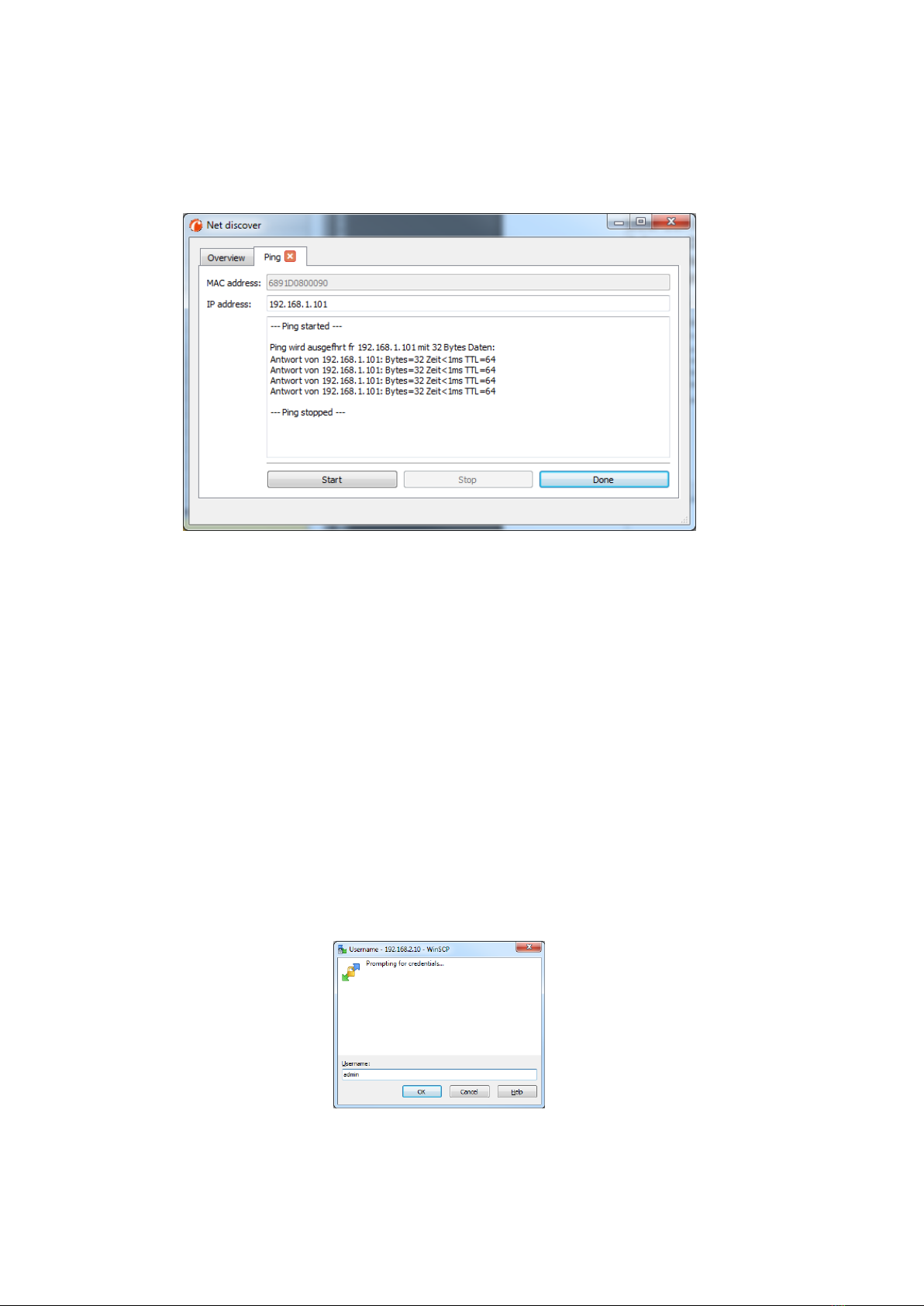
3.1.2 Connectivity test (ping)
The
Ping
command in the context menu can be used for testing the connectivity.
The push button Start starts sending ICMP ping packets to the gateway’s IP address. The push
button Stop stops sending of these ICMP packets. The dialog can be closed by clicking on the push
button Done or using the closing button at the register tab.
Figure 6: Output of the PING command at the Net discover tool
By using standard ICMP ping request packets, it is tested if the MBUS-GEB is responding correctly:
Example output:
Reply from 192.168.1.101: Bytes=32 Time<1ms TTL=64
3.1.3 Web access (HTTP)
The website of the device is opened in the browser via the
WEB
command in the context menu.
This command refers directly to the configured default browser. That website can also be accessed
directly with a browser by entering the address of the device. More information regarding the
website of MBUS-GEB can be found at section 4.
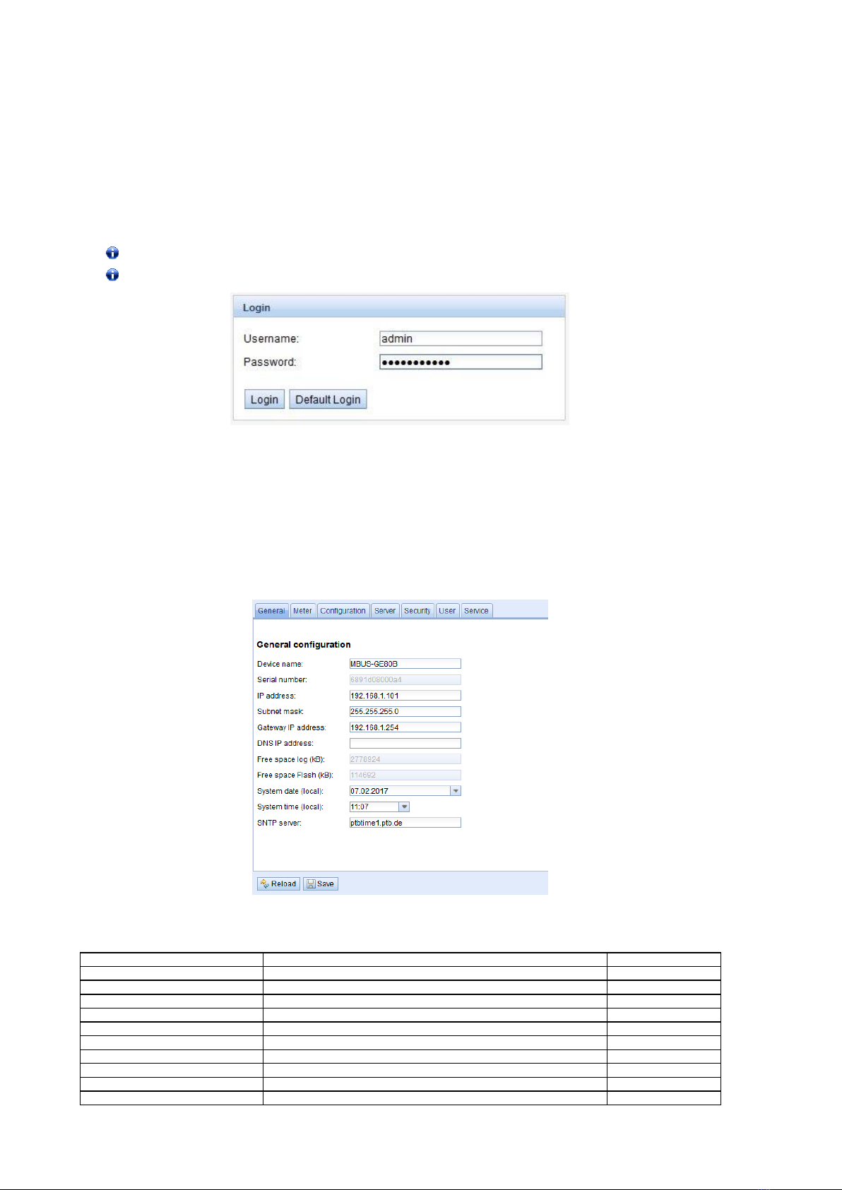
3.1.4 File access (FTPS)
An encrypted FTP session is established with the tool WinSCP by using the context menu entries
FTP and FTPS (default).
When using the context menu entry FTP, the WinSCP program will require entering a user name
and a password. The context menu entry FTP (default) sets the username and password to the user
admin’s standard credentials. Using the second method ensures a quick and uncomplicated way to
bring the MBUS-GEB into service.
Figure 7: Entering the username at the FTPS log-in
When connecting to the MBUS-GEB via FTPS the first time, a warning dialog may be displayed. This
dialog must be confirmed in order to continue to connect to the device. This is done by clicking on
the push button Yes.

MBUS-GEB - User manual
Tobias Braune, 2019-12-12 Version: 1.32 Page 15/45
© solvimus GmbH Released MBUS_GEB_UG_EN_1.32 (1).docx
Figure 8: Confirming the device's certificate
After correct log-in to the MBUS-GEB, the FTPS client program WinSCP will display a split main
window which can be used to upload or download files to and from the device. By using a context
menu, commands (for e.g. Copy, Rename or Edit) can by used to manipulate files. Drag & drop in
combination with the Windows Explorer is also supported.
Figure 9: WinSCP main windows after correct log-in
The standard log-in credentials are contained in section 4.6.
Only trained personnel are allowed to change the files and the file system, since this may
restrict the functionality of the device.
MBUS-GEB - User manual
Page 16/45 Version: 1.32 Tobias Braune, 2019-12-12
MBUS_GEB_UG_EN_1.32 (1).docx Released © solvimus GmbH
4Configuration
The MBUS-GEB is configured via its internal website. Alternatively, configuration can be done
manually by using the configuration files (see section: 8.4).
The website allows reviewing and changing of device parameters, meter configuration and also
services.
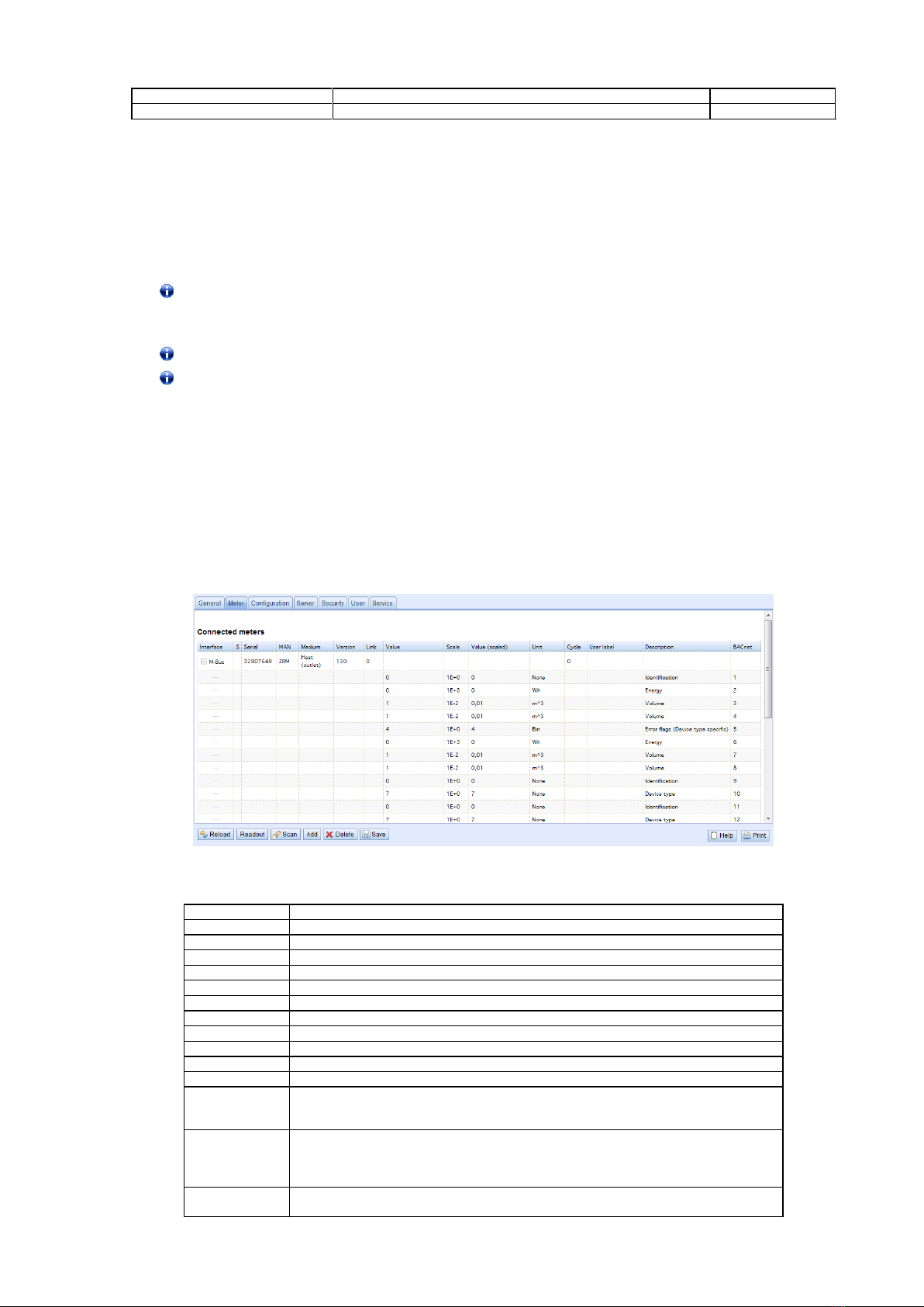
On delivery, the website automatically logs on with standard log-in data. If the standard user is
already disabled in the configuration, correct log-in data must be entered.
In order to switch to another user, please select the logout button at the upper right.
The standard log-in credentials are contained in section 4.6.
Figure 10: Login dialog
Users with write access should always log out after finishing the configuration because no other
user is allowed to have write access at the same time. If the connection stays active, no write access
is available to other users.
4.1 Tab General
The tab
General
shows a general overview on the MBUS-GEB. Following values can be reviewed
and changed:
Figure 11: Tab General
Field name
Description
Write access
Device name
Name of device (correlates to Net discover tool)
yes
Serial number
Serial number / MAC address of the device
no
IP address
IP address of device
yes
Subnet mask
Subnet mask of device
yes
Gateway address
Gateway address
yes
DNS IP
IP address of DNS server*
yes
Free space log (kB)
Free storage space on the internal log memory of the controller
no
Free space Flash (kb)
Free storage space on the internal application memory of the controller
no
System date (local)
Current local system date
yes
System time (local)
Current local system time
yes
MBUS-GEB - User manual
Tobias Braune, 2019-12-12 Version: 1.32 Page 17/45
© solvimus GmbH Released MBUS_GEB_UG_EN_1.32 (1).docx
Field name
Description
Write access
SNTP Server
Address of time server
yes
Table 8: Fields in tab General
The button Save finally saves the configuration. On Reload the last saved values are loaded and
current changes get lost.
If the network configuration has been changed, the MBUS-GEB will be available under the new IP
address after storing these changes. All established network connections to the device will be
terminated and logged in users will be logged out automatically.
Changing the network parameters of the MBUS-GEB may restrict the accessibility. If the
network parameters have been correctly set by an administrator, these shall not be
changed.
By storing the parameters via the button Save the MBUS-GEB is automatically reinitialized.
In MBUS-GEB date and time are always processed as UTC time (without time zone shift). On
the website, the web browser converts these according to the local time zone of the
computer. For example, the Central European Time or Central European Summer Time is
used in Central Europe. If the web browser uses a different time zone, the time is displayed
accordingly.
4.2 Tab Meter
The tab
Meter
displays a list of the connected meters and gives the user the ability to search for
them, manually create new meters or edit already existent meters.
The meter view displays the following information:
*wM-Bus options are not shown in the screenshot.
Figure 12: Tab Meter
Field name
Description
Interface
Interface of meter (M-Bus or wM-Bus)
Serial
Serial number of meter (number of meter)
MAN
Manufacturer of meter (abbreviation)
Medium
Medium of meter,according to column 2 of Table 18: Medium types in section 6.2.1
Version
Version number of meter
Link
Received Signal Strength Indicator (only wM-Bus)
Value
Meter reading or measurement value
Scale
Scale factor (scientific notation)
Unit
Unit,according to column 2 of Table 20:Units in section 6.2.1
Encryption key
Key for decripting wM-Bus meters
Cycle
Readout interval in seconds (entering 0 means using the general readout interval)
User label
User specific description of meter value,included in export of CSV data,allows application
specific mapping –valid characters are:A-Z,a-z,0-9,!,§,$,%,&,/,(,),=,?,+ and * comma is also
allowed, not allowed are: <,> and “
Description
Description of meter value,according to column 2 of Table 19:Measurement types
in section 6.2.1.
The Representation of the storage number,tariff,value type and raw data can be configured at
the tab Configuration using the parameter “Description mode”.
BACnet
BACnet register address which can be assigned using the function “Allocate BACnet register”
and“Deallocate BACnet register”.

MBUS-GEB - User manual
Page 18/45 Version: 1.32 Tobias Braune, 2019-12-12
MBUS_GEB_UG_EN_1.32 (1).docx Released © solvimus GmbH
Table 9: Fields in tab Meter
The meter configuration can be changed with the buttons in the bottom area of the website or the
context menu by right-clicking a meter entry. Meter entries or meter value entries can, according to
the limitations of the used interface (M-Bus or wM-Bus), be automatically searched, created, deleted
or edited.
Meter entries and meter value entries can be selected with a single mouse click. Multiple selections
are possible by holding the SHIFT key (selecting ranges) or holding the CTRL key (multiple
selections by clicking).
On activating or deactivating a meter, its meter values are automatically enabled or disabled
according to the hierarchy. If a meter is not active, it is also activated by activating one of its meter
values.
On Reload the last saved values are loaded and current changes get lost. The meter values are
updated accordingly. On delivery, the meter list of the MBUS-GEB is empty. If meters are connected
to the MBUS-GEB, an M-Bus scan can be started by pressing the Scan button. The scan mode is
configured in the tab
Configuration
. For more detailed information please see section 6.1.1.
Depending on the mode and number of connected meters, this process can take a long
time.
The scan process cannot be interrupted. The meter configuration is applied immediately after
scanning. Only additional changes must be saved manually. The meter list is additively expanded
during the scan, already existing meters will not be deleted, even if those are not available anymore.
Regarding M-Bus and wM-Bus meters, the arrangement of data in the table of tab Meters
corresponds to the order of the data in the M-Bus or wM-Bus protocol. Thus, the meaning of
the values can be compared directly with the data sheet of the meter. Alternatively, it is
possible to assign the meter values to the raw data of the meter (see parameter Description
mode on the tab Configuration, see section 4.3).
Timestamps transmitted within the M-Bus or wM-Bus protocol, are automatically assigned
to the other meter values if possible. Therefore, some of these do not appear in the table.
The configuration parameter MUC_SHOWTIMESTAMPENTRIES offers the possibility to
manually enable the display of all time stamps (see section 8.4.1).
If a scan or a change at the meter list is terminated with the error message: “Webserver
capacity exceeded”, please take note of the hints in section 7.3.8.
If there are any wM-Bus meters in the reception range of the MBUS-GEWM, these meters will be
listed at the meter list. A scan will also add received meters to the list (see section: 6.1.2).
If no scan or storing operation is in progress, currently unknown wM-Bus meters that are
received are disabled by default. These have to be enabled manually for transmission to the
communication server or log data. Unsaved wM-Bus meters get lost after a reboot.
Meters that are not found during a scan or that does not support an automated scan can be added
manually to the meter list using the button Add or using the context menu entry Add meter. More
information about manually adding meters can be found in section 6.1.3.
By double-click an entry or using the context menu entry Edit it is possible to configure the meter or
value entry. All fields in this configuration dialog correlate with the fields in the meter list (see Table
9: Fields in tab Meter). According to the used interface several fields can be enabled or disabled for
editing.
Within the configuration for an entry it is possible to set user labels for each value entry to have an
application-specific assignment of the meter and the meter values. It is also possible to set the
readout interval (parameter Cycle) independently for every meter. The decryption key needed for
encrypted wM-Bus meters can also be entered using this dialog.
Register addresses for the BACnet transmission can be assigned or reset for one or all meters by
pressing the buttons Allocate and Deallocate. During saving the configuration the BACnet
addresses will be checked for duplicates. If duplicate addresses are detected an error message will
pop up.
MBUS-GEB - User manual
Tobias Braune, 2019-12-12 Version: 1.32 Page 19/45
© solvimus GmbH Released MBUS_GEB_UG_EN_1.32 (1).docx
The push button Delete opens a window allowing deletion of selected entries of the meter list. If
wM-Bus meters are deleted and received again afterwards, these appears in the list again. This
behavior can be disabled by deactivating wM-bus listen in the tab
Configuration
.
The deletion of single meter value entries of M-Bus or wM-Bus meters is not possible.
Push the button Save for saving altered parameters.
The button Readout triggers a readout of connected meters regardless of the readout cycle. The
spontaneous readout may take some time depending on the number of connected meters. All
additionally read data is also available to the server communication. The global readout interval is
unaffected by this process.
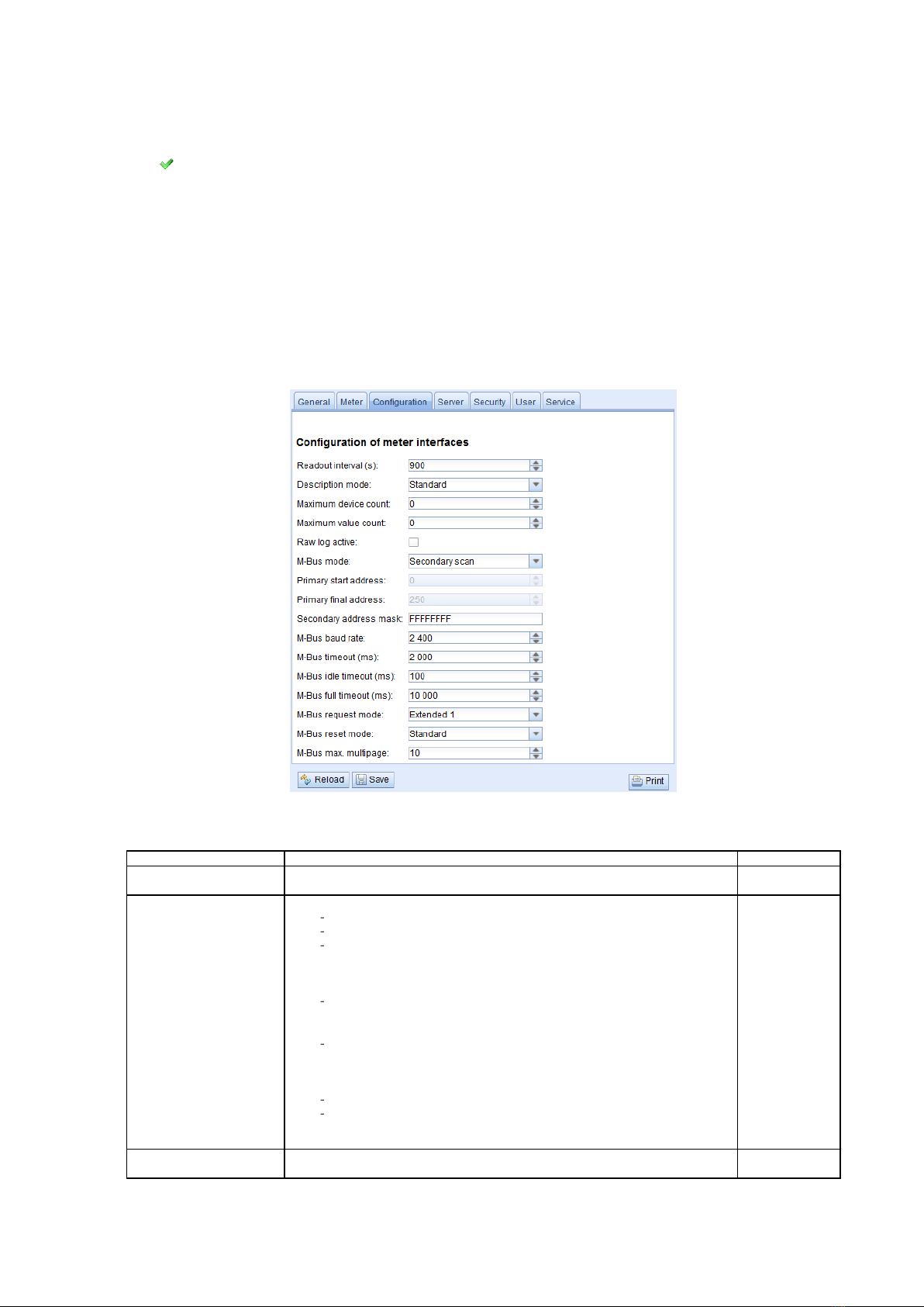
4.3 Tab Configuration
The tab
Configuration
allows configuring the meter interface of MBUS-GEB. The following
parameters are available:
*wM-Bus options are not shown in the screenshot.
Figure 13: Tab Configuration
Field name
Description
Write access
Readout interval (s)
Standard readout cycle of meters (in seconds).Value might be overwritten for each
meter by parameter Cycle in tab Meter
yes
Description mode
Mode of displaying the meter value description on the website:
None:No display of description
Standard:Display of common value description
Extended: Extended display of value description (parameters will be
displayed if they differ from 0):
Notation: Description [Memory No.] <Tariff> {min|max|error}
Example: Energy [2] <1> {max}
Extended with DIF/VIF: Extended display including DIF and VIF raw data
Notation: Description [Memory No.] <Tariff> {ValueType} # XX XX XX …
Example: Energy [2] <1> # 8C 11 04
Extended with raw data: Extended display including the raw data oft he
complete meter value entry.
Notation corresponds to Extended with DIF/VIF:
Example: Energy [2] <1> # 8C 11 04 96 47 06 00
DIF/VIF:Display of DIF/VIF raw data
Raw data:Displays the raw data oft he complete meter value entry
After changing this parameter,a readout is needed to update the meter list and to
display the relevant data.
yes
Maximum device count
Limitation of the number of meters to scan.(0:no limitation).
Already configured meters are not limitated by this parameter.
yes
MBUS-GEB - User manual
Page 20/45 Version: 1.32 Tobias Braune, 2019-12-12
MBUS_GEB_UG_EN_1.32 (1).docx Released © solvimus GmbH
Field name
Description
Write access
Maximum value count
Limitation of the number of meter value entries to read during a readout (0:no
limitation).
Already configured meter value entries are not limitated by this parameter.
yes
RAW log active
Activates the raw data log.
yes
M-Bus mode
M-Bus scan mode (secondary,reverse secondary or primary search)
yes
Primary start address
First address for primary search
yes
Primary final address
Last address for primary search
yes
Secondary address mask
Search mask for secondary search, 8 numerical characters; „F“ defines a wildcard;
missing characters will be filled up with leading zeros
yes
M-Bus baud rate
Baudrate for M-Bus communication (300-19200 baud)
yes
M-Bus timeout
M-Bus timeout until reception of first data (in ms)
yes
M-Bus idle timeout
M-Bus timeout until end of reception (in ms)
yes
M-Bus full timeout
M-Bus timeout (complete) for reception of a whole data packet (in ms)
yes
M-Bus request mode
Mode of the M-Bus readout (REQ_UD2):
Standard:Readout with REQ_UD2
Extended 1: Readout with Get-All-Data (DIF/VIF 7F 7E) and REQ_UD2
Extended 2: Readout with Get-All-Data (DIF 7F) and REQ_UD2
yes
M-Bus reset mode
Mode of the M-Bus Reset (before scan and readout):
None:no reset
Standard: Send SND_NKE to primary address of the meter or broadcast
address when using secondary adressing
Extended 1: Send SND_NKE to primary address FD and SND_NKE to
primary address of the meter or broadcast address when using secondary
addressing
Extended 2: Send SND_NKE and an Application Reset to primary address FD
and a SND_NKE to the primary address of the meter or to broadcast
address when using secondary addressing.
yes
M-Bus max.multipage
Limits the count of multipage requests
yes
wM-Bus frequency
Frequency band for the communication with wM-Bus meters
no
wM-Bus mode
wM-Bus communication mode (T or S mode) and also the deactivation of OMS
interface
yes
wM-Bus transparent mode
Select transparent mode for wM-Bus interface
yes
wM-Bus transparent port
Network port for the wM-Bus transparent mode
no
wM-Bus listen
Activates recognition and visualization of new wM-Bus devices
yes
Show encryption keys
Encryption keys as plain text
yes
Table 10: Fields in tab Configuration
The button Save finally saves the configuration. On Reload the last saved values are loaded and
current changes get lost.
By storing the parameters via the button Save the MBUS-GEB is automatically reinitialized.
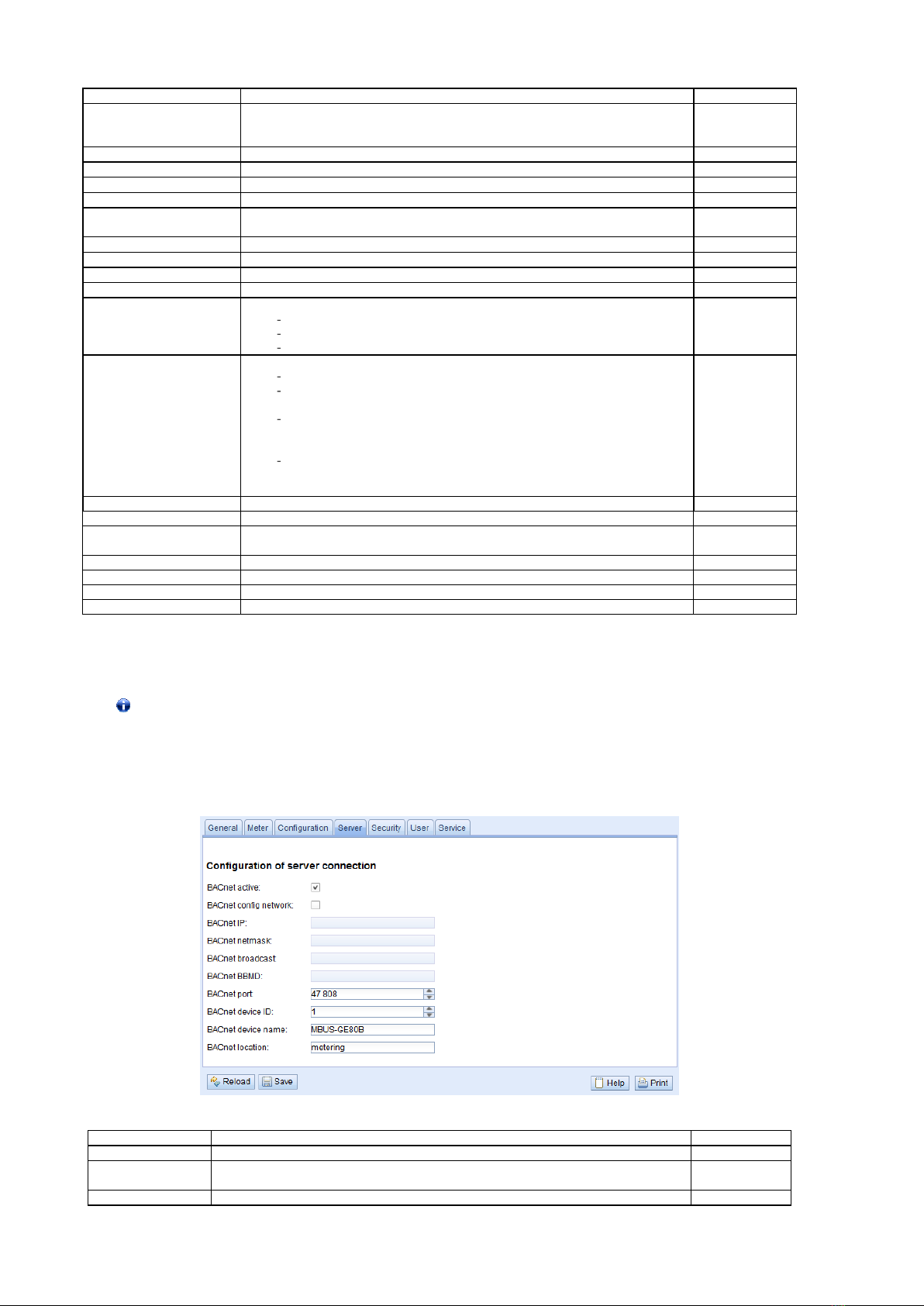
4.4 Tab Server
The tab
Server
allows configuring the BACnet/IP interface of MBUS-GEB. The following parameters
are available:
Figure 14: Tab Server
Field name
Description
Write access
BACnet active
Globally enables/disables the BACnet server functionality.
yes
BACnet config
network
Activates a second virtual network interface for the BACnet service.
yes
BACnet IP
IP address of the second virtual network interface.
yes
Table of contents
Other Solvimus Gateway manuals

Popular Gateway manuals by other brands


D-Link
D-Link DVG-2032 Quick installation guide

TEKTELIC Communications
TEKTELIC Communications T0004313 user manual

Innovaphone
Innovaphone IP6000 Administrator's manual

Develco
Develco Squid.link 2X Get started guide

AudioCodes
AudioCodes Commander MP264DB quick start guide

SolarEdge
SolarEdge ZigBee Quick installation guide


