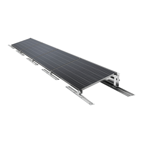
SOLYCO R-TG 108p.3 User manual

Installation manual
R-TG 108p.3, R-TG 108n.3, R-TG 108h.3, R-BG 108h.3, R-BG 108n.3, C-TG 144p.2, R-BF 108p.3, R-BF 108n.3, R-BF 120p.2, R-WF 108p.3,
R-WF 108n.3, R-WF 120p.2, R-WF 120p.2-CH, C-WF 144p.2, L-TG 120p.2, R-WF 48p, R-WF 60p

www.solyco.com Superior Solar Solutions
Installation and assembly instructions
2
Contents
1. Introduction 3
2. General information 3
2.1 Regulations and standards 3
2.2 Closure clause 4
2.3 Limitation of liability 4
2.4 General hazard warning 4
2.5 General warnings notices 4
2.6 General safety instructions 5
3. Transportation 6
4. Mechanical assembly 7
4.1 Mounting with suitable module clamps 7
4.2 Mounting with screws 7
4.3 Fastening with suitable laminate clamps 8
4.4 Clamping ranges and permissible load capacities 8
5. Electrical installation 17
5.1 Interconnection 17
5.2 Grounding 18
5.3 Check before commissioning 18
6. Maintenance and servicing 19
7. Malfunction and complaint 19
8. Disposal and recycling 19

www.solyco.com Superior Solar Solutions
Installation and assembly instructions
3
1. Introduction
Congratulations on the purchase of your high-quality PV module from SOLYCO Solar AG to generate your
own green electricity.
SOLYCO PV modules are highly reliable thanks to the selection of high-quality materials. The quality of the
solar modules is ensured by multiple tests of the products throughout the production process.
Further tests subject the products to long-term stress, and they are continuously optimized using the infor-
mation obtained. If used and treated properly, SOLYCO PV modules will work reliably for decades. As a
result, SOLYCO PV modules generate a reliable yield. We wish you a bountiful harvest. As a result, SOLYCO
PV modules generate a reliable yield. We wish you a good harvest.
Please read these assembly and installation instructions carefully before starting installation, commissio-
ning and maintenance. Failure to observe the assembly and installation instructions may result in personal
injury and/or property damage. Please keep these instructions in a safe place.
The instructions are intended for installers and trained specialist personnel who are experienced in the
assembly, operation, maintenance and dismantling of photovoltaic systems.
Symbols used
Risk of death or death
due to electric shock.
Caution Notes
2. General information
The installation and electrical interconnection of photovoltaic systems must only be carried
out by qualified personnel who are familiar with these activities through their professional
qualifications . For the assembly of the other components, the corresponding assembly inst-
ructions of the respective manufacturer must be observed. The manufacturer cannot monitor
either compliance with these instructions or the conditions under which they are carried out.
The installation instructions must be made available to the operator as part of the documentation of the
solar system, and they must be kept by the operator When planning, constructing and operating grid-con-
nected photovoltaic systems, observe the guidelines, laws and regulations of the respective country. For
additional requirements, contact your relevant local authorities and grid operator.
2.1 Regulations and standards
The listed standards and regulations represent only a selection and therefore they are not claimed to be
complete. Before and during installation, please ensure that the locally applicable standards, building
regulations and accident-prevention regulations are observed.
In addition to any possible local regulations, the following rules in particular must be observed:
■T712 VDE 0105 T100 Operation of electrical equipment
■DIN 18382 Electrical cable and wiring systems in buildings
■DIN 18334 Carpentry and timber construction work
■DIN 18338 Roofing and roof waterproofing work

www.solyco.com Superior Solar Solutions
Installation and assembly instructions
4
■DIN 18339 Plumbing work
■DIN 18351 Facade work
■DIN 18451 Scaolding Eurocode 1 (DIN EN 1991-1) Load assumptions for load-bearing
structures
■DIN V VDE V 0126-1-1 Automatic activation point for PV systems
■VDE 0298 T4 Rubber-insulated cables
■VDE 0185 Lightning protection DIN EN 61724 Monitoring of the operating behaviour of
photovoltaic systems
■VDI 6012 Bl. 2 Decentralized energy systems in the building
■UVV of the professional associations
2.2 Closure clause
The information contained in this installation and assembly manual may be changed by SOLYCO Solar AG
without prior notice.
SOLYCO Solar AG provides no warranty, either express or implied, for the information contained in these
installation and assembly instructions.
2.3 Limitation of liability
Improper execution of installation can cause damage to property and consequently endanger persons.
SOLYCO Solar AG accepts no responsibility or liability whatsoever for loss, damage or costs resulting from
or in any way connected with faulty installation, improper operation and improper use or maintenance.
The general terms and conditions of business and warranty of SOLYCO Solar AG apply. The warranty con-
ditions can be found at www.solyco.com.
2.4 General hazard warning
Risk of death from electric shock and electric arc
■Modules are always energized when exposed to light.
■The modules can only be fused at the DC switch; in the event of a fault (short circuit, ground
fault), the system continues to run on the DC side.
■Non-extinguishing arcs may occur when disconnecting contacts under load. Do not insert
(electrically conductive) parts into plugs or sockets of the modules.
■Do not install solar modules and cables with wet connectors. Tools and the working
environment should be dry.
■Observe the mounting instructions of the inverter manufacturer.
■Do not use any damaged modules.
■Keep children away from modules, inverters and other live components of the system.
■Carry out all work on pipes with extreme caution. The safety instructions of manufacturers of
other system components must be followed.
2.5 General warnings notices

www.solyco.com Superior Solar Solutions
Installation and assembly instructions
5
Risk of damage to product or environment
■Do not remove any part or nameplate axed by the manufacturer.
■Modules must not be disassembled.
■Do not expose modules to artificially concentrated sunlight.
■Do not apply paint or adhesives to modules or handle them with sharp objects.
■Do not clean modules with cleaners containing solvents, as they may damage the anti-
reflective coated glass surface.
■Do not place the modules in locations where easily combustible gases can be generated or
collected.
■Before installing the system, check the static stability of the building and the system to be
erected.
■The modules are only intended for use under temperate climatic conditions (see data sheet).
■Keep children away from the modules during transport and installation.
2.6 General safety instructions
Interim storage, removal from packaging and transport
■The modules are approved for operating temperatures of -40°C to +85°C.
■The maximum recommended installation height for SOLYCO PV modules is 2000m.
■Due to salty sea air, the modules should be installed at least 3km from any body of salt water.

www.solyco.com Superior Solar Solutions
Installation and assembly instructions
6
3. Transportation
■Always take the greatest care when handling the modules.
■Always transport the modules in the packaging provided.
■Always transport the modules with two people using both hands.
■Protective gloves and safety shoes should be worn.
■Do not use the junction box or the connection cables as a handle.
■Avoid deflection of the modules.
■Do not load, step on or drop modules.
■Do not handle modules with sharp or pointed objects.
■Keep all electrical contacts clean and dry.
■Interim storage only in dry rooms.
You should immediately check the delivered goods and their packaging for transport damage. If you
notice any damage, it is essential to note the damage on the delivery note.
The damage should be described in detail per pallet and supported by photographic documentation. Have
the forwarding agent countersign the notes.

www.solyco.com Superior Solar Solutions
Installation and assembly instructions
7
4. Mechanical assembly
General notes on module installation
The modules must be installed without voltage. The modules do not serve as a flexurally rigid connecting
or fastening element.
The SOLYCO PV modules are suitable for roof-mounted and ground-mounted systems. For mounting on
roofs, use materials suitable for the application.
All modules must be secured to the designated locations with at least four clamps or four screws. The
modules can be mounted either vertically or horizontally. Observe the permissible loads of the respective
mounting options in Chapter 4.4.
Due to thermal expansion, a minimum distance of 10mm should be maintained between the modules.
In order to avoid increased loads on modules in the edge zones and corner areas, it may be necessary
to maintain minimum distances from building edges or to provide separate proof. The wind load to be
applied for the project location must be determined from the wind zone map, which takes into account
the location situation in addition to the wind zones.
4.1 Mounting with suitable module clamps
For the positions for fixing the module clamps, refer to Chapter
4.4.
■Use M8 fixing screws.
■The clamps must be at least 7mm on the module frame.
■The clamps should have an insertion length of a minimum of 40mm.
■The module clamps should not come into contact with the front glass and must not deform
the frame.
■Make sure that no shading eects emanate from the module clamps.
■The module frame must not be changed under any circumstances.
■Use at least four clamps to fix the modules to the mounting rails of the support structure
■The torque applied should be based on the mechanical construction standard, according to
the screws used by the customer (M8 = 16 - 20Nm).
■
■
■
4.2 Mounting with screws

www.solyco.com Superior Solar Solutions
Installation and assembly instructions
8
Four to eight slot-hole mounting holes are provided in the
frame of each module. These are arranged in such a way that
optimum load-bearing capacity and fixing of the modules to
the supporting structure is ensured.
For the longest possible mounting lifetime, we strongly
recommend the use of corrosion-resistant components.
Fasten the modules as shown in the illustration at all four
mounting points with an M8 screw plus a lock washer, was-
her and nut. The torque applied should be between 16 and
20Nm. The torque applied should be between 16 and 20Nm.
4.3 Fastening with suitable laminate clamps
The frameless modules must not be mounted with any
clamps. The laminate clamps should be approved by SOLYCO
Solar AG prior to installation. The use of non-approved lami-
nate clamps will void any product and performance warranty
claims.
For the positions for fixing the module clamps, please refer
to chapter 4.4.
■M8 fastening screws should be used.
■The torque of these screws is to be 16 – 20 Nm.
■The clamps must lie at least 10 mm on the modules.
■The clamps should have an insertion length of a minimum of 150mm.
■Make sure that no shading eects emanate from the module clamps.
To ensure this, note the specified distance of the cells fromthe edge on the data sheet.
■Use at least four clamps to fix the modules to the mounting rails of the support structure
4.4 Clamping ranges and permissible load capacities
The mounting method with clamps and mounting rails corresponds to the test parameters for certification
according to IEC 61215:2016 and IEC 61730:2016.
The centre of the clamp point and clamp edges must be fully installed in the permitted mounting area.
A safety factor of 1.5 is applied to the design load. This results in the pressure and tensile load to be
applied during the mechanical load test (static).

www.solyco.com Superior Solar Solutions
Installation and assembly instructions
9
4.4.1 Fitting to inner mounting holes
Overview Description
The modules are fastened to the inner mounting
holes on the module carrier. The support rail runs
parallel to the short sides.
Module type Max. pressure
load
Max. suction load Mounting posi-
tion
R-TG 108n.3 5400Pa 2400Pa Inner
mounting holes
R-TG 108p.3 5400Pa 2400Pa „
R-TG 108h.3 5400Pa 2400Pa „
R-BG 108n.3 5400Pa 2400Pa „
R-BG 108h.3 5400Pa 2400Pa „
R-WF 108n.3 5400Pa 2400Pa „
R-WF 108p.3 5400Pa 2400Pa „
R-WF 120p.2 5400Pa 2400Pa „
R-BF 108p.3 5400Pa 2400Pa „
R-BF 108n.3 5400Pa 2400Pa „
R-BF 120p.2 5400Pa 2400Pa „
R-WF 60p 5400Pa 2400Pa „
R-WF 48p 5400Pa 2400Pa „
R-WF 120p.2 CH 5400Pa 2400Pa „
C-TG 144p.2 2400Pa 2400Pa „
R-WF 144p.2 2400Pa 2400Pa „

www.solyco.com Superior Solar Solutions
Installation and assembly instructions
10
4.4.2 Bolting to external mounting holes
Overview Description
The modules are attached to the module rail at
the specified mounting positions on the long side
by means of module clamps. The support rail runs
parallel to the short sides.
Module type Max. pressure
load
Max. suction load Mounting posi-
tion
R-TG 108n.3 2400Pa 2400Pa Outer
mounting holes
R-TG 108h.3 2400Pa 2400Pa „
R-TG 108p.3 2400Pa 2400Pa „
R-BG 108h.3 2400Pa 2400Pa „
R-BG 108n.3 2400Pa 2400Pa „
R-WF 108n.3 2400Pa 2400Pa „
R-WF 108p.3 2400Pa 2400Pa „
R-WF 120p.2 2400Pa 2400Pa „
R-BF 108n.3 2400Pa 2400Pa „
R-BF 108p.3 2400Pa 2400Pa „
R-BF 120p.2 2400Pa 2400Pa „
R-WF 60p 2400Pa 2400Pa „
R-WF 48p 2400Pa 2400Pa „
R-WF 120p.2 CH 2400Pa 2400Pa „
C-TG 144p.2 2400Pa 2400Pa „
C-WF 144p.2 3600Pa 3600Pa „

www.solyco.com Superior Solar Solutions
Installation and assembly instructions
11
4.4.3 Clamping at four points on the long side of the module
Overview Description
The modules are attached to the module rail at
the specified mounting positions on the long side
by means of module clamps. The support rail runs
parallel to the short sides.
Module type Max. pressure
load
Max. suction load Mounting posi-
tion
R-TG 108n.3 2400Pa 2400Pa D = ¼ L ±50mm
R-TG 108p.3 2400Pa 2400Pa „
R-TG 108h.3 2400Pa 2400Pa „
R-BG 108n.3 2400Pa 2400Pa „
R-BG 108h.3 2400Pa 2400Pa „
R-WF 108n.3 3600Pa 1600Pa „
R-WF 108p.3 3600Pa 1600Pa „
R-WF 120p.2 3600Pa 1600Pa „
R-BF 108p.3 3600Pa 1600Pa „
R-BF 108p.3 3600Pa 1600Pa „
R-BF 120p.2 3600Pa 1600Pa „
R-WF 60p 5400Pa 2400Pa „
R-WF 48p 5400Pa 2400Pa „
R-WF 120p.2 CH 3600Pa 1600Pa „
C-TG 144p.2 2400Pa 2400Pa „
C-WF 144p.2 5400Pa 3600Pa „

www.solyco.com Superior Solar Solutions
Installation and assembly instructions
12
4.4.4 Clamping at four points on the short sides of the module
Overview Description
The modules are attached to the module support
rail at the specified mounting positions on the short
side by means of module clamps. The support rail
runs parallel to the long sides.
Module type Max. pressure
load
Max. suction load Mounting posi-
tion
R-TG 108n.3 2400Pa 2400Pa D = 1/5 W ±50mm
R-TG 108p.3 2400Pa 2400Pa „
R-TG 108h.3 2400Pa 2400Pa „
R-BG 108n.3 2400Pa 2400Pa „
R-BG 108h.3 2400Pa 2400Pa „
R-BF 108n.3 3600Pa 1600Pa „
R-BF 108p.3 3600Pa 1600Pa „
R-BF 120p.2 3600Pa 1600Pa „
R-WF 108n.3 3600Pa 1600Pa „
R-WF 108p.3 3600Pa 1600Pa „
R-WF 120p.2 3600Pa 1600Pa „
R-WF 60p 5400Pa 2400Pa „
R-WF 48p 5400Pa 2400Pa „
R-WF 120p.2 CH 3600Pa 1600Pa „
C-WF 144p.2 5400Pa 3600Pa „
C-TG 144p.2 2400Pa 2400Pa D = 50mm – 250mm

www.solyco.com Superior Solar Solutions
Installation and assembly instructions
13
4.4.5 Clamping at the corners of the short module side
Overview Description
The modules are attached to the module support
rail at the corners on the short side by means of
module clamps. There are no module supports
running under the modules or under the module
frame.
Module type Max. pressure
load
Max. suction load Mounting posi-
tion
R-TG 108n.3 2400Pa 2400Pa Corner points short side
R-TG 108p.3 2400Pa 2400Pa „
R-TG 108h.3 2400Pa 2400Pa „
R-BG 108n.3 2400Pa 2400Pa „
R-BG 108h.3 2400Pa 2400Pa „
R-BF 108n.3 1600Pa 1600Pa „
R-BF 108p.3 1600Pa 1600Pa „
R-WF 108n.3 1600Pa 1600Pa „
R-WF 108p.3 1600Pa 1600Pa „
R-BF 120p.2 1600Pa 1600Pa „
R-WF 120p.2 1600Pa 1600Pa „

www.solyco.com Superior Solar Solutions
Installation and assembly instructions
14
4.4.6 Long-side mounting – insertion system
Overview Description
The modules are attached to the long side with
the insertion system. The module support rail runs
parallel under the long sides.
Module type Max. pressure
load
Max. suction load Mounting posi-
tion
R-TG 108n.3 5400Pa 2400Pa Insertion system
- long side
R-TG 108p.3 5400Pa 2400Pa „
R-TG 108h.3 5400Pa 2400Pa „
R-BG 108n.3 5400Pa 2400Pa „
R-BG 108h.3 5400Pa 2400Pa „
R-BF 108n.3 5400Pa 2400Pa „
R-BF 108p.3 5400Pa 2400Pa „
R-BF 120p.2 5400Pa 2400Pa „
R-WF 108n.3 5400Pa 2400Pa „
R-WF 108p.3 5400Pa 2400Pa „
R-WF 120p.2 5400Pa 2400Pa „
R-WF 60p 5400Pa 2400Pa „
R-WF 48p 5400Pa 2400Pa „
R-WF 120p.2 CH 5400Pa 2400Pa „
C-WF 144p.2 2400Pa 2400Pa „
C-TG 144p.2 2400Pa 2400Pa „

www.solyco.com Superior Solar Solutions
Installation and assembly instructions
15
4.4.7 Short-side mounting – insertion system
Overview Description
The modules are attached to the short side with
the insertion system. The support rail runs parallel
under the short sides.
Module type Max. pressure
load
Max. suction load Mounting posi-
tion
R-TG 108n.3 2400Pa 2400Pa Insertion system
- short side
R-TG 108p.3 2400Pa 2400Pa „
R-TG 108h.3 2400Pa 2400Pa „
R-BG 108n.3 2400Pa 2400Pa „
R-BG 108h.3 2400Pa 2400Pa „
R-BF 108n.3 1600Pa 1600Pa „
R-BF 108p.3 1600Pa 1600Pa „
R-BF 120p.2 1600Pa 1600Pa „
R-WF 108n.3 1600Pa 1600Pa „
R-WF 108p.3 1600Pa 1600Pa „
R-WF 120p.2 1600Pa 1600Pa „

www.solyco.com Superior Solar Solutions
Installation and assembly instructions
16
4.4.8 Fixing with four laminate clamps on the long sides
Overview Description
The modules are attached to the module carrier
using four laminate clamps at the specified
mounting positions on the long side. There are no
module supports running under the modules or
under the module frame.
Module type Max. pressure
load
Max. suction load Mounting posi-
tion
L-TG 120p.2 1600Pa 1600Pa D = 300-400mm

www.solyco.com Superior Solar Solutions
Installation and assembly instructions
17
5. Electrical installation
Risk of death from electric shock and electric arc
Consider locally applicable standards and regulations.
SOLYCO PV modules are classified in application class A (certified according to IEC 61730) and comply
with protection class II, provided that electrical installation has been carried out in accordance with regu-
lations.
When laying the cables it must generally be ensured that the connecting cables of the modules are not
exposed to mechanical stresses. The modules must be installed without voltage.
The maximum permissible bending radii of the connecting cables must be observed. Conductor loops
should be avoided or kept to a minimum to reduce the risk of indirect lightning strikes.
Unplugged contact plugs must be protected from all kinds of contamination. This includes the time span
of installation, storage, and transportation.
Corroded plug connectionscaused by leaks cause high contact resistance. This can lead to a deteriora-
tion in performance or even damage to your system.
The cables and connectors should not rest on the floor and should not be exposed to high humidity.
Opening and modification of the junction box, its removal from the connecting cables or disassembly
of the frame or frame parts are not approved. Use only standardized photovoltaic cables with a cable
cross-section of at least 4mm².
It is possible that higher currents and voltages are generated than under the standardized STC test con-
ditions according to the type plate and data sheet. This must be taken into account when designing
equipment such as cables, fuses and controls. For this purpose, the information on the PV module for the
short-circuit current ISC and the open-circuit voltage Uoc (set at the lowest expected temperature at the
site of use) should be applied with a factor of 1.25 under STC conditions.
5.1 Interconnection
Note: Only modules of the same type and performance class should be interconnected.
Interconnection limits for series connection or for modules in one string: For the maximum
series arrangement of modules, the specified system voltage (Umax. Syst. = 1500V see data sheet) must
be obeyed
Calculation formula for determining the maximum number (interconnection limit) of PV modules connec-
ted in series:
Max. System voltage: The lowest value in the system is decisive

www.solyco.com Superior Solar Solutions
Installation and assembly instructions
18
Uoc: PV module open-circuit voltage (see data sheet)
TK (Uoc): Temperature coecient of the PV module open circuit voltage
ΔT: Temperature dierence between STC (25°C) and the lowest ambient temperature
Without a string fuse, a maximum of two module strings may be arranged in parallel (see the calculation
formula below). Please note the value specified in the data sheet(15A) for the reverse current carrying
capacity.
Interconnection limits for parallel connection or for strings connected in parallel. Calculation formula for
determining the maximum number (interconnection limit) of strings connected in parallel:
IR: Max. Reverse current carrying capacity of the PV module according to data sheet
Isc: Short-circuit current of the PV module according to data sheet
TK (Isc): Temperature coecient of the PV module short-circuit current according to data sheet
ΔT: Temperature dierence between STC (25°C) and the highest PV module temperature
5.2 Grounding
Even if the modules are certified according to protection class II, the circumstances may require the ins-
tallation of equipotential bonding.
SOLYCO PV modules have 5.1mm (Ø) ground bores (6x) in all 4 poles
and oer the option of installing equipotential bonding cables to
ground the system.
All local regulations and ordinances for electrical installations must
be adhered to during installation.
Modules without a module frame have no grounding capability.
5.3 Check before commissioning
Checklist before commissioning:
■Check for insulation faults and closing behaviour
■Check the open-circuit voltage to detect circuit faults
■Has the polarity been correctly observed?
■Check the connectors for correct seating

www.solyco.com Superior Solar Solutions
Installation and assembly instructions
19
6. Maintenance and servicing
Observe the safety and warning instructions when servicing and cleaning. The general and
local regulations must be observed.
A photovoltaic system requires relatively little maintenance. The cleaning eect from the combination
of module inclination and rain is usually sucient for normal contamination such as dust and dirt. Heavy
soiling, such as leaves or bird droppings, should be removed to prevent partial shading and resulting yield
reduction. The module surface can be cleaned with plenty of water and a soft sponge. Do not use metal
objects or aggressive cleaning agents to avoid damaging the surface.
In addition, the following points should be checked by a specialist company at fixed intervals:
■Strength of the substructure on the battens
■Integrity, tight fit and corrosion-free operation of cable connections, screw connections and
clamp connections
■Functionality of the fuse components
■Measurement of string voltages and currents during operation
7. Malfunction and complaint
If, despite the high-quality standards of our PV modules, you have a reason to complain, please contact
your dealer directly or contact:
SOLYCO Solar AG
Baseler Straße 60
12205 Berlin
+49 30 403 619 42
www.solyco.com
8. Disposal and recycling
Note
Defective or old solar modules must be disposed of properly and must not be disposed of along with
household waste.
We oer our customers the return of SOLYCO PV modules and their recycling. For more information, you
can contact us by e-mail or telephone, or at
The company SOLYCO SOLAR AG is registered as a manufacturer of the device type Large Photovoltaic
Modules under the WEEE Reg. No. EN 63944028.
MA-SOLYCO-Module-2023-08_v1_en
This manual suits for next models
16
Table of contents
Popular Solar Panel manuals by other brands
patura
patura Solar Panel 25W user manual
TOMMATECH
TOMMATECH TT400-80PMKB12-250 installation manual
Kyocera
Kyocera KD185GX-LPU datasheet

Viessmann
Viessmann Vitosol-F Series installation instructions

Battery Power Solutions
Battery Power Solutions BPS SP40 manual
Worcester
Worcester FKT Series installation instructions

