5 │
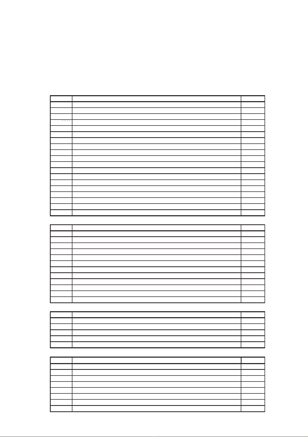
5.1 Mounting pump stations and accessories onto LYRA
SCOPE OF DELIVERY
LYRA Thermal Store, code 12228 (others under codes 12229, 12230, 12231
differ just in number of heating circuits or the possibility to connect the
fresh water station to a recirculation pipe):
12228: LYRA 1000 VVS Thermal Store with 2 heating circuits and DHW recirc.
Code Name Qty
11999 PSW 1000 FWS Thermal Store for LYRA 1 pcs
11998 Insulation for PSW 1000 FWS Thermal Store, NEODUL - code 11999 1 pcs
12224 Pump station for Thermal Store, 2 circuits 1pcs
9909 S2 Solar 3 pump station, ST25/6, 2-12 l/min, 3/4" 1 pcs
9717 Fresh water station with FWC3 controller, with recirculation 1 pcs
12226 Kit to connect assemblies onto LYRA 1pcs
12227 Kit to connect solar pump station onto LYRA 1 pcs
12687 TSC3 Assy for LYRA 1 pcs
13983 T-Piece Assy for LYRA 1 pcs
12689 Pressure gauge assy for LYRA 1 pcs
12690 Angled Ball Valve Assy for LYRA 1 pcs
13236 Ball valve and elbow assy for LYRA and VEGA tanks 1 pcs
13234 Kit for connecting TSV assy to LYRA tank 1 pcs
13237 Accessory kit for LYRA and VEGA tanks 1 pcs
12222 Cover for pump station with 2 circuits 1 pcs
12223 Front insulation for cover for pump station with 2 circuits 1pcs
12720 Top insulation for cover for pump station with 2 circuits 1 pcs
12713 Black knurled screw, M6x1-10 PA 6.6 4 pcs
13437 Kit for connecting expansion vessel to LYRA 1 pcs
12226: Assy Connection Kit for LYRA
Code Name Qty
11271 DN25 water pipe, 1"MF,250-500 1 pcs
13984 DN25 pipe (5/4” nut) l=580 mm 1 pcs
3016 DN25 water pipe, 1"MF,200-400 1 pcs
3041 DN20 water pipe,3/4"MF,250-500 2 pcs
7691 Brass hex plug, 1” M 1 pcs
8306 3/4” elbow, M/F, brass 1 pcs
6447 Pipe insulation, diam. 28, 13 mm thick (2 m) 1.2 m
7187 Pipe insulation, diam. 35, 13 mm thick (2 m) 1.5 m
12996 M6x16 stainless steel bolt (hex socket) DIN 912/A2 8 pcs
7853 6.5 washer (large diameter 3d) 8pcs
9980 1” nut gasket - 18,5x30x2 PTFE 3 pcs
9978 3/4" nut gasket - 15x24x2 PTFE 3 pcs
13237 : Accessory Kit for LYRA and VEGA
Code Name Qty
10474 Thermometer d=63 with sheath l=150, 1/2“, rear conn., 0-120°C 2 pcs
605 Safety valve 3 bar,1/2" F/F 1 pcs
6971 1/2" hex nipple (M/M), thick wall 2 pcs
11965 1/2" ball valve, F/F 1 pcs
11708 Automatic ½“ air release valve, with check valve 1 pcs
13437 : Expansion Vessel Connection Kit for Lyra/Vega
Code Name Qty
11969 6/4" FF ball valve 1pcs
7627 Hex nipple, 6/4“ x 6/4“, M/M, thick wall 2 pcs
8757 T-piece in brass 6/4" FFF 1 pcs
8766 Reducing hex nipple 1"x6/4" M/M 1 pcs
7049 T-piece in brass 1" FFF 1 pcs
6969 Hex nipple, 1“x1“, M/M, thick wall 1 pcs
7701 Reducing hex nipple, 1“x1/2“, M/M, brass 1 pcs
11713 1/2“ drain valve, no handle, with cap 1 pcs
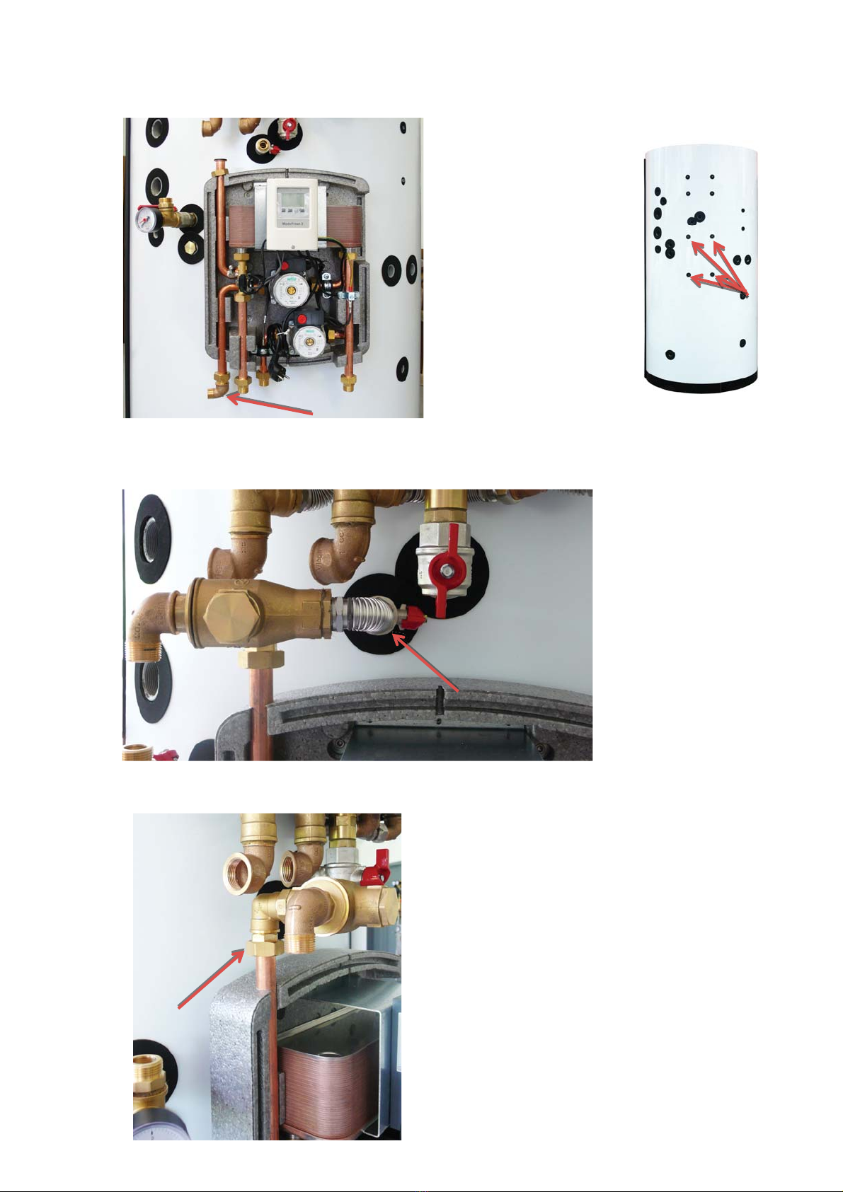
5 - Connections
14866