SOMAS MTV Operation manual

Mi-205 EN
Operation and service instruction
Buttery valves
Type MTV/FSV
Type MTV/FSVW Wafer design
Type MTVF/FSVF Flanged design
Type MTVL/FSVL Lugged design
Type FSVG Wafer design with guiding lugs
Nominal pressure PN 10 - 25, Class 150
Nominal Size DN 80 - 500 MTV,MTVF
DN 100 - 500 FSVW/FSVF/FSVL/FSVG
DN 80 - 350 MTVL
Edition: 2021-04

2
Edition: 2021-04 Original document - Mi-205 EN
Introduction
This operating manual is intended for the operating, maintenance and
supervisory personnel.
This operating manual also describes components, equipment and ancillary units
which are not or only partially included in the scope of supply.
The operating personnel must have read, understood and must comply with this
operating manual.
We keep the right to do any technical changes which are necessary to improve the
product without prior notice.
Copyright
Copyright by SOMAS Instrument AB. No part of this publication may be
reproduced, stored in a retrieval system, or transmitted in any form or by any
means, graphic, electronic, mechanical, photocopying, recording, taping, or
otherwise without the prior permission of the copyright owner.
Supplier
SOMAS Instrument AB
Norrlandsvägen 26-28
SE-661 40 SÄFFLE
SWEDEN
Phone: +46 (0)533 167 00
E-mail: sales@somas.se
Website: www.somas.se

3
Original document - Mi-205 EN Edition: 2021-04
Contents
1 Introductory information 6
1.1 Explanation of warnings, symbols and signs 6
1.1.1 Warnings 6
1.1.2 Symbols and signs 7
2 Safety 8
2.1 Safety instructions 8
2.1.1 General dangers 8
2.1.2 Hazards due to electrical equipment 8
2.1.3 Additional hazards 8
2.1.4 State of the art 9
2.1.5 Preconditions for using the valve 9
2.2 Designated use of the valve 10
2.2.1 Use 10
2.2.2 Liability for non-designated use 10
2.3 Organizational measures 11
2.3.1 Availability of operating manual 11
2.3.2 Additional regulations 11
2.3.3 Checks 11
2.3.4 Protective equipment 11
2.3.5 Rebuilds or modifications at the valve 11
2.3.6 Replacing damaged parts 11
2.4 Selection and qualification of personnel 11
2.5 Safety instructions for butterfly valves 12
3 Description 15
3.1 General information 15
3.2 Function of the valve 15

4
Edition: 2021-04 Original document - Mi-205 EN
4 Technical specifications 17
4.1 Specifications 17
4.1.1 Gaskets 17
4.2 Fastening torque for flanges 19
4.2.1 Fastening torque for flanges valve body 19
4.2.2 Fastening torque for stuffing box 20
4.2.3 Tightening torque for screws in valves 21
5 Assembly 22
5.1 Unpacking and transportation 22
5.2 Installation of the valve in the pipeline 23
5.2.1 Important information for installation 24
5.2.2 End of line installations 24
5.3 Start up 26
5.4 Disassembly of the pneumatic actuator 27
5.5 Positioning of the shaft with disassembled actuator 28
5.6 Assembly of the pneumatic actuator 29
5.6.1 Actuator mounting alternatives 31
6 Maintenance 32
6.1 Disassembly of the butterfly valve from pipeline 32
6.2 Maintenance 33
6.2.1 Procedure to evaluate a leakage on a butterfly valve with pneumatic 34
actuator installed in a pipeline
6.2.2 Procedure to evaluate a leakage on a butterfly valve with gear 36
installed in a pipeline
6.3 Installation and disassembly of the stuffing box 38
6.4 Replacing the seat (standard metal seat) 40
6.4.1 Disassembly 41

5
Original document - Mi-205 EN Edition: 2021-04
6.4.2 Cleaning, lubrication and assembly 41
6.5 Replacing the PTFE seat 42
6.5.1 Disassembly 43
6.5.2 Cleaning, lubrication and assembly 43
6.6 Replacing the Fire safe seat 44
6.6.1 Disassembly 45
6.6.2 Cleaning, lubrication and assembly 45
6.7 Adjustment of the end position on pneumatic actuator 46
6.7.1 Setting of the ”closed” position on the butterfly valve 47
6.7.2 Setting of the ”open” position on the butterfly valve 47
6.8 Adjustment of the end position on gear 48
6.8.1 Setting of the ”closed” position on the butterfly valve 49
6.8.2 Setting of the ”open” position on the butterfly valve 49
6.9 Leak test of the valve 50
6.10 Components 52
6.10.1 MTV DN 80-150, with metal seat 52
6.10.2 MTV DN 200-300, with metal seat 53
6.10.3 MTV DN 350-500, with metal seat 54
6.10.4 MTV DN 80-150, with PTFE seat 55
6.10.5 MTV DN 200-300, with PTFE seat 56
6.10.6 MTV DN 350-500, with PTFE seat 57
6.10.7 FSV DN 100-150, with Fire safe seat 58
6.10.8 FSV DN 200-500, with Fire safe seat 59
6
Edition: 2021-04 Original document - Mi-205 EN
1 Introductory information
To enable you to find information quickly and reliably in the operation manual,
this chapter familiarises you with the structure of the operating manual.
This manual uses symbols and special characters which make it easier for you to
find information. Please read the explanations of the symbols given in the section
below.
Ensure that you read all the safety instructions in this operating manual very
carefully.
You will find safety instructions in section 2, in the foreword to the sections and
before any working instructions.
1.1 Explanation of warnings, symbols and signs
1.1.1 Warnings
Warnings are used in this operating manual to warn against injury and material
damage. Always read and observe these warnings! Warnings are identified by the
following symbols:
In this manual are used diverse types of safety and warning notices:
Danger!
International
Safety symbol
Type of danger.
Advise for imminent danger. Not attention of the advices could be mortal or cause severe
injuries as a consequence.
Explanation of the countermeasures.
Warning!
International
Safety symbol
Type of danger.
Advise for imminent danger. Not attention of the advices could cause severe injuries or property
damage as a consequence.
Explanation of the countermeasures.
Attention!
International
Safety symbol
Type of danger.
Advise for possible danger. Not attention of the advices could cause property damage as a
consequence.
Explanation of the countermeasures.

7
Original document - Mi-205 EN Edition: 2021-04
Note
i
Advices and give tips for better understanding of the manual or a better handling of the valve.
1.1.2 Symbols and signs
Symbols and signs are used in this operating manual to provide fast access to
information.
1.1.2.1 Symbols and signs in the text
Symbol Denotation Explanation
Operating instructions This means there is an action to be carried out.
1.
2.
Operating instructions,
multi-step
Work instructions must be carried out in the
sequence shown.
Deviations from the sequence shown may result in
damages to the valve and accidents.
•
–
Lists, two-stage No activities are linked with lists.
➔Cross-reference References to images, tables, other sections or other
instructions.
Tab.1-1 Symbols in the text

8
Edition: 2021-04 Original document - Mi-205 EN
2 Safety
2.1 Safety instructions
2.1.1 General dangers
Sources of danger resulting in general hazards:
• Mechanical hazards
• Electrical hazards
2.1.2 Hazards due to electrical equipment
Due to the permanent dampness, electrically-operated machine parts
represent a potential source of danger.
Comply with all regulations on electrical equipment in damp areas!
2.1.3 Additional hazards
2.1.3.1 Entanglement, crushing and cut/sever hazards
• by moving machine parts left exposed, by removing covers for inspection,
sampling, etc.
• by automatic operated valves
2.1.3.2 Burning or scalding hazards
• by opening or leaving open function-check and/or sampling openings
on systems operating at high temperatures (above 40°C)
• by operating temperature >= 70°C. Short contacts (approx. 1s) of the skin
with the surface of the valve may cause burns (pr EN 563)
• by operating temperature = 65°C. Longer contacts (approx. 3s) of the skin
with the surface of the valve may cause burns (pr EN 563)
• by operating temperature 55°C…65°C. Longer contacts (approx. 10 ... 3s)
of the skin with the surface of the valve may cause burns (pr EN 563)
2.1.3.3 Explosion hazards
A high surface temperature on a valve and actuator, constitutes (a risk for burn
injuries, and) a risk of ignition of explosive atmospheres in ATEX applications.
The surface temperature of the equipment is not dependent on the equipment
itself, but on the ambient conditions and the process conditions. The protection
from the surface temperature is the responsibility of the end user, and must be
effectuated before the equipment is put into service.

9
Original document - Mi-205 EN Edition: 2021-04
2.1.4 State of the art
This product has been built by SOMAS Instrument AB in accordance with state-
of-the-art standards and the recognized safety rules. Nevertheless, its use may
constitute a risk to life and limb of the user or of third parties, or cause damage
to the valve and to other material property, if:
• the product is not used as designated
• the product is operated or repaired by untrained personnel
• the product is modified or converted improperly and/or
• the safety instructions are not observed
Therefore, every person involved in erecting, operating, inspecting, maintaining,
servicing and repairing the valve must read, understand and observe the complete
operating instructions, particularly the safety instructions.
2.1.5 Preconditions for using the valve
The valve only has to be used:
• in perfect technical condition
• as designated
• according to the instructions in the operating manual, and only by safety-
conscious persons who are fully aware of the risks involved in operating the
valve
• if all protective devices are installed and operative
Rectify immediately any functional disorders, especially those affecting the safety
of the valve!

10
Edition: 2021-04 Original document - Mi-205 EN
2.2 Designated use of the valve
2.2.1 Use
The valves are appropriate to be used in pulp and paper industry, chemical
industry, shipbuilding industry, energy industry and offshore industry.
Particular data to the operation and limit values are specified on the data sheet
“Si-205EN (MTV) and Si-202EN (FSV)”.
The operating values, limit values and setting data must not deviate from the
values specified in the operating manual and correspondig information sheet
without consulting the manufacturer! The manufacturer cannot be held liable
for any damages resulting from non-observance of the operating manual.
The user is responsible for knowing the impact from the media on the valve,
the resulting wear rate, and establishing maintenance interval, to maintain safe
operation.
2.2.2 Liability for non-designated use
Using the valve for other purposes than those mentioned previously is considered
contrary to its designated use. For resulting damages of this, SOMAS Instrument
AB is not liable! The user take the risk.

11
Original document - Mi-205 EN Edition: 2021-04
2.3 Organizational measures
2.3.1 Availability of operating manual
The operating manual has to be stored and be readily available!
2.3.2 Additional regulations
In addition to the operating manual, it have to be observed all other generally
applicable legal and other mandatory regulations relevant to accident prevention
and environmental protection! Direct the personnel to comply with them!
2.3.3 Checks
Periodically check that the personnel carry out the work in compliance with
the operating manual and that they pay attention to risks and safety factors.
2.3.4 Protective equipment
Use when necessary protective equipment.
2.3.5 Rebuilds or modifications at the valve
Do not make any rebuilds or modifications at the valve yourself, which can affect
the security of the valve.
2.3.6 Replacing damaged parts
Valve parts that are not in perfect condition must be replaced immediately
with original spare parts! Use only original spare and wear parts from
SOMAS Instrument AB.
On unauthorized parts is not guarantee that they have been designed and
manufactured according to the application.
2.4 Selection and qualification of personnel
Operation, maintenance and repairing works require special knowledge and
may only be carried out by trained technical specialists or qualified personnel
authorized by the user.

12
Edition: 2021-04 Original document - Mi-205 EN
2.5 Safety instructions for butterfly valves
Operation of the butterfly valve is always subject to the local safety and accident
prevention regulations.
Danger!
Risk of injury!
Observe movements of the disc.
Keep hands, tools and other objects away from the area where the disc moves when the
actuator is connected to compressed air system. Single action actuators may move to “open”
or “closed” position without being connected to the air system.
Warning!
Before carrying out maintenance or repair work on the butterfly valve with actuator or
installation and removal of the butterfly valve from the pipeline, always disconnect the
compressed air supply to the actuator.
Single action actuators may move to “open” or “closed” position without being connected
to the air system.
Warning!
Ensure that personnel who work with, install or repair the butterfly valve are appropriately
trained. This prevents unnecessary damage and accidents or injury to personnel.
The maintenace and assembly personnel must be familiar with the process of installing and
disassembling the butterfly valve in a process line, the special and possible risks of the process
and the most important safety regulations.
The repair and assembly personnel must be familiar with the risks when handling pressurised
equipment, hot and cold surfaces, dangerous substances and substances which represent
a hazard to health.
Warning!
Do not exceed the design data of the butterfly valve!
Exceeding the design data marked on the butterfly valve may lead to damage and uncontrolled
escape of the pressurised medium.
Both the damage as such and the pressurised medium may lead to injuries to personnel.
Warning!
Do not remove the butterfly valve from the line as long as it is pressurised!
Dismantling or disassembly of a pressurised butterfly valve leads to an uncontrolled loss of
pressure. Always isolate the relevant butterfly valve in the pipe system; despressurise the
butterfly valve and remove the medium before working on the butterfly valve.

13
Original document - Mi-205 EN Edition: 2021-04
Warning!
Before assembling or disassembling the pneumatic actuator of a butterfly valve installed in the
pipeline depressurise the relevant valve in the pipeline system, isolate the valve and remove the
medium before working on the valve.
The pressurised medium may lead to injuries to personnel.
Warning!
Inform yourself of the properties of the medium. Protect yourself and your environment from
hazardous or poisonous substances.
Observe the safety instructions in the safety data sheets of the manufacturers. Ensure that no
medium can enter the pipeline during maintenance work.
Warning!
Before replacing the stuffing box of a butterfly valve installed in the pipeline depressurise the
relevant valve in the pipeline system, isolate the valve and remove the medium before working
on the valve.
The pressurised medium may lead to injuries to personnel.
Danger!
Risk of injury!
Observe movements of the valve disc.
Keep hands, tools and other objects away from the area where the valve disc moves. The valve
with valve disc mounted may work as a cutting tool. Do not leave any foreign objects in the
valve body. The valve disc of the butterfly valve always works as a separate device. There is no
difference whether an actuator is installed or not. The position of the disc may change during
transport or handling of the butterfly valve.
Warning!
Protect yourself against noise - use the relevant safety equipment.
The butterfly valve may cause noise in the pipeline. The noise level depends on the type of
application and can be determined with the SOMAS software SomSize.
Additional noise sources in the vicinity of the butterfly valve may increase the noise level.
Warning!
Beware of very cold or hot surfaces!
The body of the butterfly valve may become very cold or very hot during operation. Protect
yourself against frostbite and burns.

14
Edition: 2021-04 Original document - Mi-205 EN
Warning!
When transporting and handling the butterfly valve, observe its weight.
Never lift the valve by its positioner, limit switch, solenoid valve or piping. Place the hoisting
ropes securely according to lift instruction.
The butterfly valve or parts thereof may injure persons if dropped.
Do not walk under suspended loads.

15
Original document - Mi-205 EN Edition: 2021-04
3 Description
3.1 General information
The SOMAS butterfly valve is used for control shut-off and hand operation. The
valve is suitable for liquids, vapours and gases in a wide temperature range.
Due to the sophisticated triple-eccentric design and the special shape of the disc
a solid stainless steel seat can be used. This combination gives a solution resistant
against high flow velocity and guarantees no leakage even under severe conditions.
The seat is available in different stainless qualities and is replaceable.
The butterfly valve is designed as a wafer style valve. As alternative there is a lug
type version available.
The butterfly valve is checked and ready for use at delivery and can be equipped
with actuators, valve positioners as well as with other accessories.
3.2 Function of the valve
Fig.3-1 MTV Fig.3-2 FSV
MTV
Metal seat Code D
Control valve: EN60534-4 V Shut-off valve: EN12266-1 Rate D
PTFE seat Code A
Control valve: EN60534-4 V Shut-off valve: EN12266-1 Rate C
Control valve: EN60534-4 VI
(optional)
Shut-off valve: EN12266-1 Rate B
(optional)
FSV
Fire safe Code F
Control valve: EN60534-4 V Control valve: EN60534-4 VI
(optional)
Shut-off valve: EN12266-1 Rate B
(optional)
Shut-off valve: EN12266-1 Rate C
(optional)
The SOMAS MTV valve is equipped with a metalic seat.
The tightness on the main flow direction is according to:
The SOMAS FSV valve is equipped with a Fire safe seat.
The tightness on the main flow direction is according to:

16
Edition: 2021-04 Original document - Mi-205 EN
Note
i
Use gaskets with the nominal size of the valve, to have a leak-proof sealing in both flow
directions.
The valve is adjustable. This means, the more the valve is closed the tighter it
becomes (➔Fig.3-1).
Through the sophisticated triple eccentric design, the seat is relased from the disc
when opening the valve. This reduce wearing and extend the durability of the
valve.
To close the butterfly valves for liquids need less torque than valves for vapors
and gases.
The butterfly valve is tight in both flow directions. The preferred flow direction
is the direction towards the flat side of the disc. This direction is marked with
arrows on both sides of the valve.

17
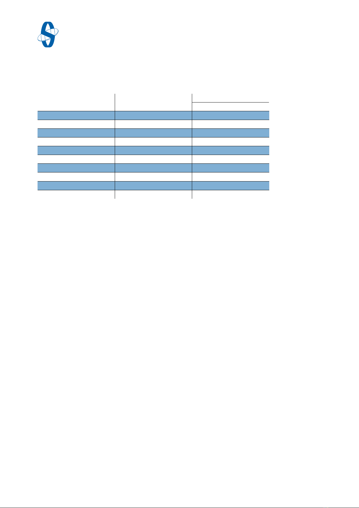
Original document - Mi-205 EN Edition: 2021-04
DN Max. inside dia.
(di) (mm)
Outside dia. (dy) (mm)
PN 10 PN 16 PN 25
80* 89 142 142 142
100 115 162 162 168
125 141 192 192 194
150 169 218 218 224
200 220 273 273 284
250 273 328 329 340
300 324 378 384 400
350 356 438 444 457
400 407 489 495 514
500 508 594 617 624
4 Technical specifications
4.1 Specifications
4.1.1 Gaskets
Note
i
To ensure pressure on the cover plate use only gaskets with right inside diameter.
For installation between pipe flanges acc. to PN 10-25, the inside diameter acc. to
EN 1514-1 of the gasket should not be exceeded, see (➔Tab.4-1).
Tab.4-1 Gaskets diameter acc. to EN 1514-1
* DN80 only for MTV
18
Edition: 2021-04 Original document - Mi-205 EN
Tab.4-2 Gaskets diameter acc. to ASME Norm
DN Max. inside dia.
(di) (mm)
Outside dia. (dy) (mm)
Class 150
80* 89 136
100 114 174
125 141 196
150 168 222
200 219 279
250 273 340
300 324 410
350 356 451
400 406 515
500 508 606
* DN80 only for MTV
To fit between pipe flanges acc. to Class 150, the dimensions acc. to
ASME B16.21 RF are valid, whereas the following dimensions for gaskets are valid
(➔Tab.4-2).
19
Original document - Mi-205 EN Edition: 2021-04
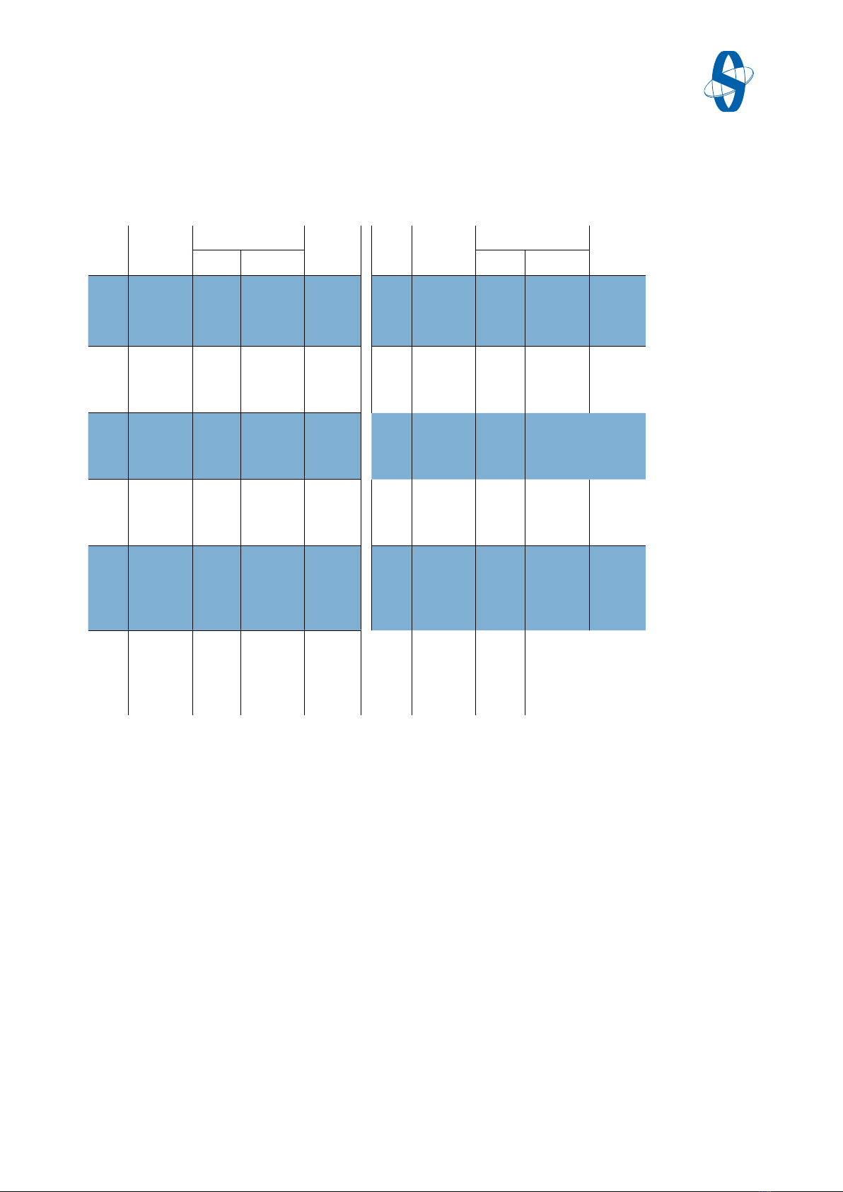
* DN80 only for MTV
Tab.4-3 Fastening torque for flanges valve body
4.2 Fastening torque for bolts
4.2.1 Fastening torque for flanges valve body
DN PN/Class Screw Torque
(Nm) 1
DN PN/Class Screw Torque
(Nm) 1
Dim. Quantity Dim. Quantity
80* 10, 16, 25
/150
M16
5/8“
8
4
65
120
300 10
16
25
/150
M20
M24
M27
7/8“
12
12
16
12
160
180
205
230
100 10,16
25
/150
M16
M20
5/8“
8
8
8
80
95
70
350 10
16
25
/150
M20
M24
M30
1“
16
16
16
12
215
235
340
280
125 10,16
25
/150
M16
M24
3/4“
8
8
8
90
110
110
400 10
16
25
/150
M24
M27
M33
1“
16
16
16
16
240
300
445
300
150 10,16
25
/150
M20
M24
3/4“
8
8
8
120
140
130
450 10
16
25
/150
M24
M27
M33
1 1/8”
20
20
20
16
210
300
395
405
200 10
16
25
/150
M20
M20
M24
3/4“
8
12
12
8
175
120
140
180
500 10
16
25
/150
M24
M30
M33
1 1/8“
20
20
20
20
245
410
480
355
250 10
16
25
/150
M20
M24
M27
7/8“
12
12
12
12
140
150
200
170
1The information in the table refers to lubricated bolts. The correction factor for new, unlubricated bolts is 1.5.
Tighten the bolts alternately until the correct tightening torque is reached.
Tightening torque applies to flat gaskets corresponding to non-reinforced and reinforced graphite according to
EN 12516-2: 2014 with m-factor according to ASME 2.0 to 2.5. Maximum thickness for gasket: 2.0 mm. Tightening
torque must not be exceeded, because then the functionality of the valve can be compromised. Tightening
torques in Nm are designed for gaskets according to EN 1514-1, ASME B16.21 and counter flanges according to
EN 1092-1, EN 1759-1, ASME B16.47.
20
Edition: 2021-04 Original document - Mi-205 EN
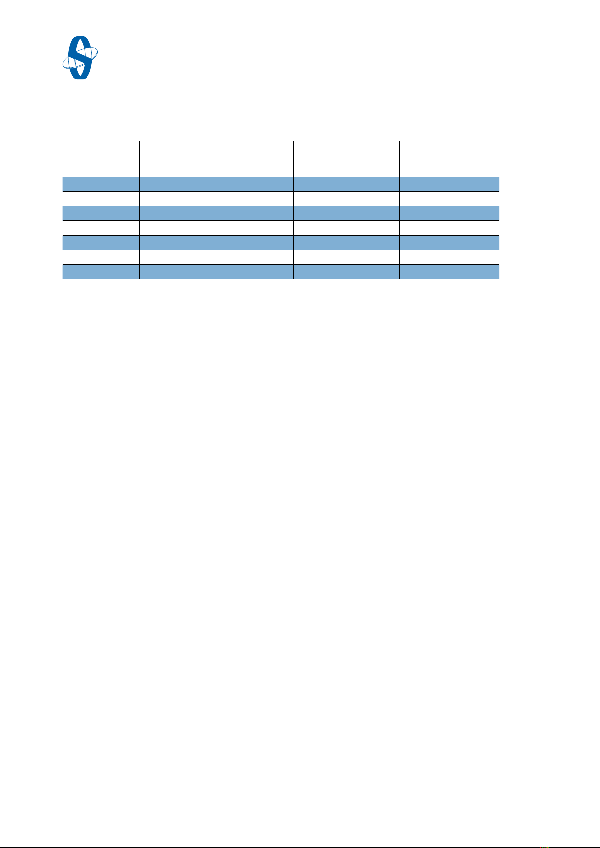
The fastening torque at the table are valid for new, properly fixed stuffing boxes. If
the threads are not lubricated, the highest torque specifications are valid.
By leakage while operating, the compression of the stuffing box can be improved
by higher torque values.
Generally: To aviod a leakage, all the nuts have to be fastened the same, only little
differences at the torque are tolerated.
DN
Shaft ø
(mm)
Stuffing box ø
di/dy (mm)
Tightening torque,
graphite stuffing box
(Nm
Tightening torque,
PTFE stuffing box
(Nm)
80*,100,125 20 20/30 610
150,200 25 25/35 10 10
250 30 30/40 12 15
300 35 35/45 15 15
350 40 40/55 25 25
400 50 50/65 40 35
500 60 60/75 60 50
4.2.2 Recommended fastening torque for MTV/FSV stuffing box
Tab.4-4 Torque for MTV/FSV stuffing box
* DN80 only for MTV
This manual suits for next models
6
Table of contents
Other SOMAS Control Unit manuals


